1988 PONTIAC FIERO engine oil
[x] Cancel search: engine oilPage 377 of 1825
6A2-26 2.8 LITER V-6
2. Remove the spark plugs. Installation
3. Remove
crankshaft pulley and torsional damper. 1. Install rear main bearing oil seal in cylinder block
4. Remove oil pan and oil pump. and
rear bearing cap grooves.
5. Remove water pump, crankcase front cover, 2. Lubricate seal with engine oil. Keep oil off
camshaft sprocket and timing chain. parting
line surface.
3. Install main bearings in cylinder block and main
6. Check the connecting rod caps for cylinder
bearing caps then lubricate bearing surface with
number identification. If necessary mark them.
engine oil.
7. Remove the connecting rod caps and
push the
4. 1n;tall crankshaft, being careful not to damage
pistons to top of bores.
bearing surfaces.
8. Remove main bearing caps and lift crankshaft out 5. Recheck bearing clearances using plastigage.
of cylinder block. 6.
Apply a thin coat of anaerobic sealant
# 1052357
9. Remove rear
main bearing oil seal and main or
equivalent to rear of the block mating surface
bearings from cylinder block and main bearing or corresponding
surface or rear main cap only.
caps. Do
not allow sealer on crankshaft or seal.
7. Install main bearing caps with arrow pointing
Cleaning and Inspection toward front of engine.
8. Torque all except
#3 main bearing cap bolts to
1. Wash crankshaft in solvent and dry with
specifications. Torque
#3 main bearing cap bolts
compressed air. to 14-16
N-m (10-12 lbs. ft.) then tap end of
2. Measure
dimensions of main bearing journals and crankshaft, first rearward then forward with a
crankpins with a micrometer for out-of-round, lead
hammer. This will line up rear main bearing
taper or undersize (See Specifications). and crankshaft
thrust surfaces.
Retorque all main
3. Check
crankshaft for run-out by supporting at bearing
cap bolts to specifications.
the front and rear main bearings journals in "V" 9. Measure crankshaft
end play with a feeler gage.
blocks and check at the front and rear Force crankshaft forward and measure clearance
intermediate journals with a dial indicator (See between the front of the
#3 main bearing and
Specifications). crankshaft thrust surface.
4. Replace or recondition the crankshaft if out of 10.
Install flywheel and torque to specifications.
specifications.
SPROCKET OR GEAR REPLACEMENT
Remove crankshaft sprocket using Tool J-5825,
install using Tool J-5590.
GENERAL DATA
TYPE .................................................................................................................................... 60" V-6
DISPLACEMENT
............................................................................................................. 2.8 Liter
RPO
........................................................................................................................................... LB8
BORE ......................................................................................................................................... 89
STROKE
................................... .... ............................................................................................... 76
COMPRESSION RATIO
....................................................................................................... 8.9: 1
FIRING ORDER
.......................................................................................................... 1-2-3-4-5-6
Cylinder Bore
DIAMETER .............................................................................................................. 88.992-88.070
OUT OF ROUND
............................................................................................................. .02 Max.
TAPER-THRUST SIDE
................................................................................................. .02 Max.
Piston
CLEARANCE .................................................................................................................. .O 17-,043
Piston Ring
Page 380 of 1825
V-8 ENGINE BA3-1
SECVON 6A3
TER V8 V N CODE E
TER V8 V N CODE F
TER V8 V N CODE 8
CONTENTS
GENERAL DESCRIPTION .......................... 6A3- 1
ENGINE LUBRICATION .......................... 6A3-2
ON-VEHCILE SERVICE ............................... 6A3-5
...................................... Powertrain Mounts 6A3-5
Intake Manifold ........................................... 6A3-6
Dipstick Tube .............................................. 6A3-7
Exhaust Manifold ........................................... 6A3-7
........................................ Rocker Arm Cover 6A3-8
Rocker Arm and Push Rods ...................... 6A3-8
Valve Stem Oil Seal and/or
Valve Spring
................................................ 6A3-9
Valve Lifters .................................................. 6A3- 10
............................. Cylinder Head Assembly 6A3- 1 1
...................................... Rocker Arm Studs 6A3- 14
...................................... Valve Guide Bores 6A3- 14
Valve Seats .................................................. 6A3- 14
Valves ........................................................... 6A3- 15
Torsional Damper ........................................ 6A3- 15
.
............................. Crankcase Front Cover .... 6A3- 1 5
Oil Seal (Front Cover) ................................... 6A3- 16
Camshaft ...................................................... 6A3- 16
Camshaft Bearings ............................. .. ....... 6A3- 17
Oil Pan ......................................................... 6A3- 18
..................................................... Oil Pump 6A3- 18
............................. Connecting Rod Bearings 6A3- 19
.............................................. Main Bearings 6A3-20
........................................... Rear Main Seal 6A3-22
........... Connecting Rod & Piston Assemblies 6A3-23
............................................ Cylinder Block 6A3-26
............................... Oil Filter Bypass Valve 6A3-27
.......................................... Engine Assembly 6A3-27
................................................... Crankshaft 6A3-28
..................... Sprocket or Gear Replacement 6A3-28
......................................... SPECIFICATIONS 6A3-28
GENERAL DESCRIPTION
CYLINDER BLOCK CAMSHAFT AND DRIVE
The cylinder block is made of cast iron and has The
cast iron camshaft is supported by 5 bearings
8 cylinders arranged in a "V" shape with 4 cylinders and
is chain driven. A steel crankshaft sprocket drives
in each bank.
5 main bearings support the crankshaft the
timing chain which in turn drives the camshaft
which is retained by bearing caps that are machined through a cast iron 'procket.
with the block for proper alignment and clearances.
Cam lobes are ground, hardened and tapered
Cylinders are completely encircled by coolant Jackets, with the high side toward the rear. This, cou~led with
CYLINDER HEAD a sphericalYface on the lifter, causes the "alve lifters to
rotate.
Camshaft bearings are lubricated through oil
The cast iron cylinder heads feature individual
holes which intersect the main oil gallery. The main oil intake and exhaust Ports for each cylinder. Valve gallery is rifle drilled down the center of the block, guides are integral, and rocker arms are retained on above the individual pressed studs.
CRANKSHAFT AND BEARINGS
The crankshaft is cast nodular iron and is
supported by five main bearings
#5 is the end thrust
bearing.
Main bearings are lubricated from oil holes which
intersect the camshaft bearings. The camshaft bearings
are fed oil by the main oil gallery which is rifle drilled
down the center of the block, above the camshaft. Two
additional oil galleries are on either side of the main oil
gallery to provide an oil supply for the hydraulic lifters.
PISTONS AND CONNECTING RODS
The pistons are made of cast aluminum alloy
using two compression rings and one oil control ring.
Piston pins are offset 1/16"
(1.6mm) toward the thrust
side (right hand side) to provide a gradual change in
thrust pressure against the cylinder wall as the piston
travels its path. Pins are Chromium steel and have
a
floating fit in the pistons They are retained in the
connecting rods by a press fit. Connecting rods are
made of forged steel. Full pressure lubrication
is
directed to the connecting rods by drilled oil passages
from the adjacent main bearing journal.
Page 381 of 1825
6A3-2 V-8 ENGINE
VALVE TRAIN
A very simple ball pivot-type train is used.
Motion is transmitted from the camshaft through the
hydraulic lifter and push rod to the rocker arm. The
rocker arm pivots on its ball and transmits the
camshaft motion to the valve. The rocker-arm ball is
retained by a nut.
HYDRAULIC VALVE LIFTERS
Hydraulic Valve Lifters are used to keep all parts
of the valve train in constant contact.
The hydraulic lifter assembly consists of: a roller,
the lifter body, which rides in the cylinder block boss,
a plunger, a push rod seat, a metering valve, a plunger
spring, a check ball and spring, a check ball retainer
and a push rod seat retainer.
When the lifter is riding on the low point of the
cam, the plunger spring keeps the plunger and push rod
seat in contact with the push rod.
When the lifter body begins to ride up the cam
lobe, the check ball cuts off the transfer of oil from the
reservoir below the plunger. The plunger and lifter
body then rise as a unit, pushing up the push rod and
opening the valve.
As the lifter body rides down the other side of the
cam, the plunger follows with it until the valve closes.
The lifter body continues to follow the cam to its low
point, but the plunger spring keeps the plunger in
contact with the push rod. The ball check valve will then
move off its seat and the lifter reservoir will
remain full.
INTAKE MANIFOLD
The intake manifold for those engines with
carburetors are made of cast iron or aluminum double
level design for efficient fuel distribution. An Exhaust
Gas Recirculation (EGR) port is also cast into the
manifold for the mixture of exhaust gases with the fuel
air mixture.
The intake manifold for those vehicles equipped
with
PFI is a cast aluminum unit. It centrally supports
a fuel rail with
8 fuel injectors.
EXHAUST MANIFOLDS
Two cast iron exhaust manifolds are used to
direct exhaust gases from the combustion chambers to
the exhaust system. The left hand side manifold
receives a heat shield that is used to route heated air
to the air cleaner. for better fuel vaporization during
warm-up.
COMBUSTION CHAMBERS
Combustion Chambers are cast to insure uniform
shape for all cylinders. Spark plugs are located between
the intake and exhaust valves. The contoured wedge
shape of the combustion chamber minimizes the
possibility of detonation, facilitates breathing and
provides swirling turbulence for smooth, complete
combustion.
ENGINE LUBRICATION
Full pressure lubrication through a full flow oil through drilled passages, to the camshaft and
filter, is furnished by a gear-type oil pump. The crankshaft to lubricate the bearings. The valve lifter oil
distributor, driven by a helical gear on the camshaft,
gallery feeds the valve lifters which, through hollow
drives the oil pump. The main oil gallery feeds oil,
push rods, feed the individually mounted rocker arms.
Page 385 of 1825
6A3-6 V-8 ENGINE
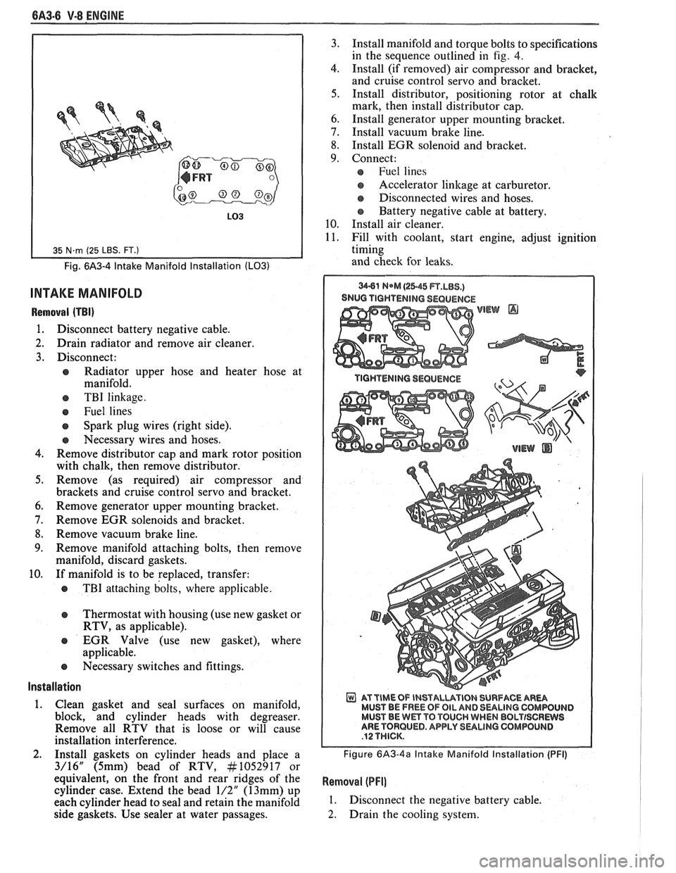
Fig. 6A3-4 Intake Manifold Installation (LO31
INTAKE MANIFOLD
Removal (TBI)
1. Disconnect battery negative cable.
2. Drain radiator and remove air cleaner.
3. Disconnect:
e Radiator upper hose and heater hose at
manifold.
e TBI linkage.
e Fuel lines
Spark plug wires (right side).
e Necessary wires and hoses.
4. Remove distributor cap and mark rotor position
with chalk, then remove distributor.
5. Remove (as required) air compressor and
brackets and cruise control servo and bracket.
6. Remove generator upper mounting bracket.
7. Remove EGR solenoids and bracket.
8. Remove vacuum brake line.
9. Remove manifold attaching bolts, then remove
manifold, discard gaskets.
10. If manifold is to be replaced, transfer:
e TBI attaching bolts, where applicable.
Thermostat with housing (use new gasket or
RTV, as applicable).
EGR Valve (use new gasket), where
applicable.
e Necessary switches and fittings.
lnstallation
1. Clean gasket and seal surfaces on manifold,
block, and cylinder heads with degreaser.
Remove all RTV that is loose or will cause
installation interference.
2. Install gaskets on cylinder heads and place a
3/16" (5mm) bead of RTV, At1052917 or
equivalent, on the front and rear ridges of the
cylinder case. Extend the bead
1/2" (13mm) up
each cylinder head to seal and retain the manifold
side gaskets. Use sealer at water passages. 3.
Install manifold and torque bolts to specifications
in the sequence outlined in
fig. 4.
4. Install (if removed) air compressor and bracket,
and cruise control servo and bracket.
5. Install distributor, positioning rotor at chalk
mark, then install distributor cap.
6. Install generator upper mounting bracket.
7. Install vacuum brake line.
8. Install EGR solenoid and bracket.
9. Connect:
Fuel lines
s Accelerator linkage at carburetor.
@ Disconnected wires and hoses.
Battery negative cable at battery.
10. Install air cleaner.
11. Fill with coolant, start engine, adjust ignition
timing
and check for leaks.
SNUG TIGHTENING SEQUENCE
WEW @
AT TIME OF INSTALUVIBN SURFACE AR- MUST BE FREE OF OIL AND 8ULlNG CQMWUIJD MUST BE Wm TO TOUCH WHEN BBLTISCRWS ARE TORQUED. APPLY SULINO GOMPOLINB
Figure 6A3-4a Intake Manifold Installation (PFI)
Removal (PFI]
1. Disconnect the negative battery cable.
2. Drain the cooling system.
Page 388 of 1825
V-8 ENGINE 6A3-9
surfaces of rocker arms and rocker arm balls
with "Molykote" or its equivalent.
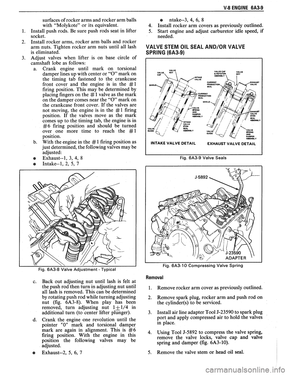
1. Install push rods.
Be sure push rods seat in lifter
socket.
2. Install
rocker arms, rocker arm balls and rocker
arm nuts. Tighten rocker arm nuts until all lash
is eliminated.
3. Adjust
valves when lifter is on base circle of
camshaft lobe as follows:
a. Crank engine until mark on torsional
damper lines up with center or
"0" mark on
the timing tab fastened to the crankcase
front cover and the engine is in the
#l
firing position. This may be determined by
placing fingers on the
# 1 valve as the mark
on the damper comes near the
"0" mark on
the crankcase front cover. If the valves are
not moving, the engine is in the
# 1 firing
position. If the valves move as the mark
comes up to the timing tab, the engine is in
#6 firing position and should be turned
over one more time to reach the
#1
position.
b. With
the engine in the
# 1 firing position as
just determined, the following valves may be
adjusted:
e Exhaust--1, 3, 4, 8
e Intake--1, 2, 5, 7
, ,
Fig. 6A3-8 Valve Adjustment - Typical
c. Back out adjusting nut until lash is felt at
the push rod then turn in adjusting nut until
all lash is removed. This can be determined
by rotating push rod while turning adjusting
nut (fig.
6A3-8). When play has been
removed, turn adjusting nut
1 + 1/4 in
additional turn (to center lifter plunger).
d. Crank
the engine one revolution until the
pointer
"0" mark and torsional damper
mark are again in alignment. This is
#6
firing position. With the engine in this
position the following valves may be
adjusted.
e Exhaust--2, 5, 6, 7
o ntake--3, 4, 6, 8
4. Install rocker arm covers as previously outlined.
5. Start engine and adjust carburetor idle speed, if
needed.
VALVE STEM OIL SEAL AND/OR VAL\/E
SPRING (6A3-9)
INTAKE VALVE DETAIL
EXHAUST VALVE DETAIL
Fig. 6A3-9 Valve Seals
Fig.
6A3-10 Compressing Valve Spring
Removal
1. Remove rocker arm cover as previously outlined.
2. Remove
spark plug, rocker arm and push rod on
the
cylinder(s) to be serviced.
3. Install air line adapter Tool J-23590 to spark plug
port and apply compressed air to hold the valves
in place.
4. Using Tool J-5892 to compress the valve spring,
remove the valve locks, valve cap and valve
spring and damper (fig.
6A3-10).
5. Remove
the valve stem or head oil seal.
Page 389 of 1825
QA3-10 V-8 ENGINE
lnstallation
1. Install valve stem seal over valve stem and seat
against head.
2. Set
the valve spring and damper, oil shedder and
valve cap in place. Compress the spring with Tool
J-5892 and install oil seal in the lower groove of
the stem, making sure the seal is flat and not
twisted. A light coat of oil on the seal will help
prevent twisting.
3. Install
the valve locks and release the compressor
tool making sure the locks seat properly in the
upper groove of the valve stem. Grease may be
used to hold the locks in place while releasing the
compressor tool.
4. Using tool J-23994, apply vacuum to the valve
cap to make sure no air leaks past the seal.
5. Install spark plug and torque to 22 lb. ft.
(30N.m).
6. Install and adjust valve mechanism as previously
outlined.
VALVE LIFTERS
Hydraulic valve lifters very seldom require
attention. The lifters are extremely simple in design,
readjustments are not necessary, and servicing of the
lifters requires only that care and cleanliness be
exercised in the handling of parts.
Valve Lifter Diagnosis
1.
Momentarily Noisy When Car is Started:
This condition is normal. Oil drains from the
lifters which are holding the valves open when the
engine is not running. It will take a few seconds
for the lifter to fill after the engine is started.
2. Intermittently Noisy On Idle Only. Disappearing
When Engine Speed is Increased:
Intermittent clicking may be an indication of a
pitted check valve ball, or it may be caused by
dirt.
Correction: Clean the lifter and inspect. If check
valve ball is defective, replace lifter.
3. Noisy At Slow Idle Or With Hot Oil, Quiet With
Cold Oil Or As Engine Speed Is Increased:
High leak down rate. Replace suspect lifter.
4. Noisy At High Car Speeds And Quiet At Low
Speeds:
a. High oil level
- Oil level above the "Full"
mark allows crankshaft counterweights to
churn the oil into foam. When foam is
pumped into the lifters, they will become
noisy since a solid column of oil is required
for proper operation. Correction: Drain oil
inti1 proper level is obtained.
b. Low oil level - Oil level below the "Add"
mark allows the pump to pump air at high
speeds which results in noisy lifters.
Correction: Fill until proper oil level is
obtained.
c. Oil pan bent on bottom or pump screen
cocked or loose, replace or repair as
necessary. 5.
Noisy At Idle Becoming Louder As Engine Speed
Is Increased To 1500 rpm:
This noise is not connected with lifter
malfunction. It becomes most noticeable in the
car at 10 to 15 mph "1" (Low) range, or 30 to
35
mph "DM (Drive) range and is best described as
a
hashy sound. At slow idle, it may be entirely
gone or appear as a light ticking noise in one or
more valves. It is caused by one or more of the
following:
a. Badly worn or scuffed valve tip and rocker
arm pad.
b. Excessive valve stem to guide clearance.
c. Excessive valve seat
runout.
d. Off square valve spring.
e. Excessive valve face
runout.
f. Valve spring damper clicking on rotator.
Removal
1.
Remove intake manifold as previously outlined.
2. Remove valve mechanism as previously outlined.
3. Remove valve lifter retainer.
4. Remvoe valve lifter restrictor.
5. Remove valve lifters (Fig.
6A3-7). Place valve
lifters in a rack so that they may be reinstalled in
the same location.
Installation
1.
Coat roller of valve lifters with "Molykote" or its
equivalent and install valve lifters.
2. Install valve lifter restrictor.
3. Install valve lifter retainer.
4. Install intake manifold as previously outlined.
5. Install and adjust valve mechanism as outlined.
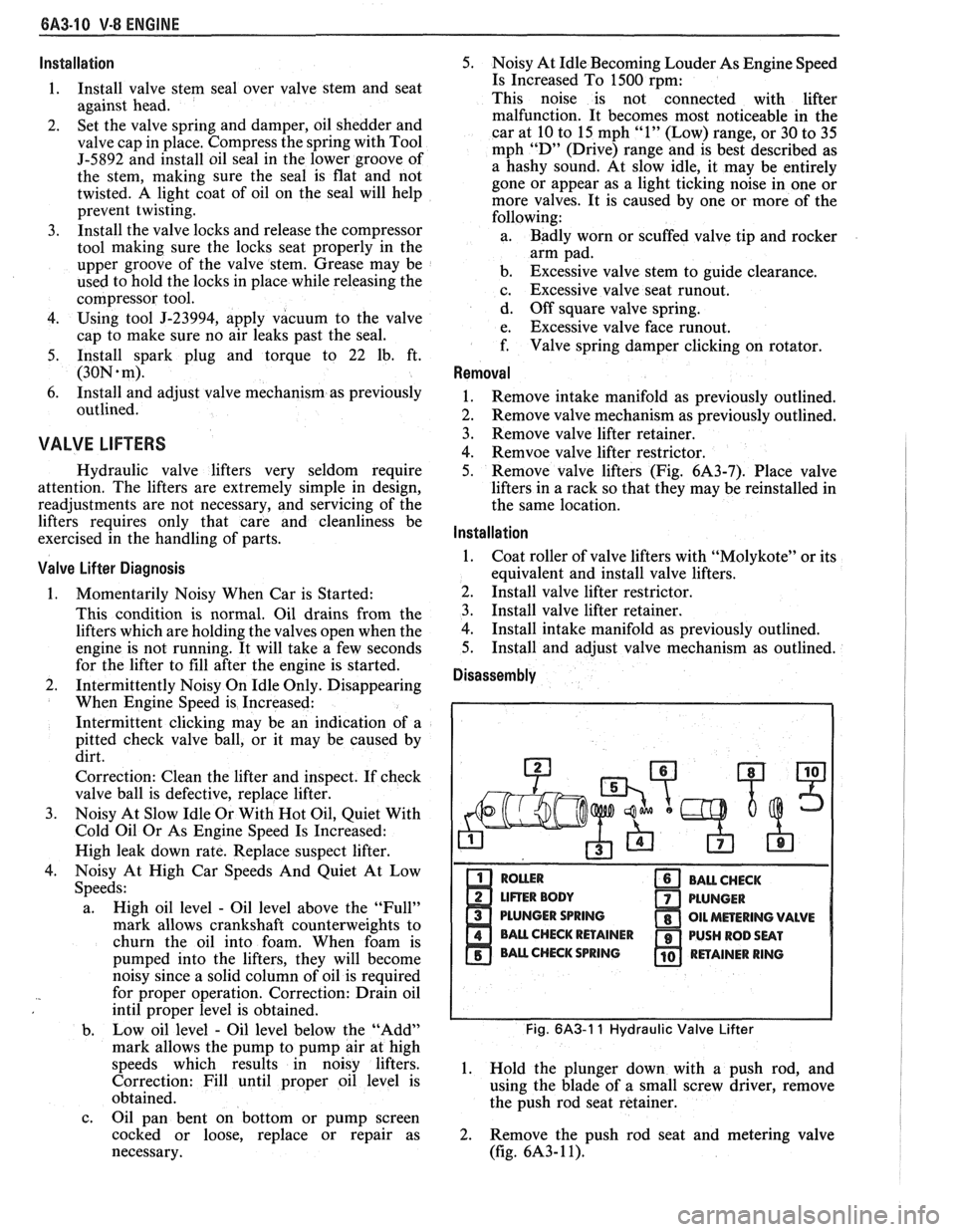
Disassembly
PLUNGER SPRING
Fig. 6A3-1 1 Hydraulic Valve Lifter
1. Hold the plunger down with a push rod, and
using the blade of a small screw driver, remove
the push rod seat retainer.
2. Remove the push rod seat and metering valve
(fig.
6A3- 1 1).
Page 390 of 1825
V-8 ENGINE BA3-11
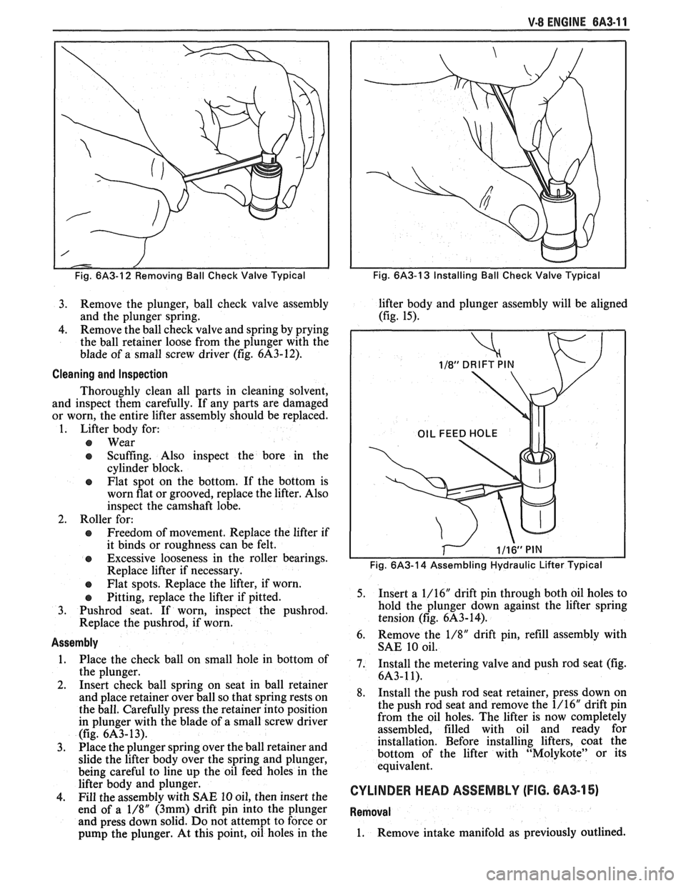
Fig. 6/43-12 Removing Ball Check Valve Typical
3. Remove the plunger, ball check valve assembly
and the plunger spring.
4. Remove
the ball check valve and spring by prying
the ball retainer loose from the plunger with the
blade of a small screw driver (fig.
6A3-12).
Cleaning and Inspection
Thoroughly clean all parts in cleaning solvent,
and inspect them carefully. If any parts are damaged
or worn, the entire lifter assembly should be replaced.
1. Lifter body for:
@ Wear
e Scuffing. Also inspect the bore in the
cylinder block.
@ Flat spot on the bottom. If the bottom is
worn flat or grooved, replace the lifter. Also
inspect the camshaft lobe.
2. Roller for:
@ Freedom of movement. Replace the lifter if
it binds or roughness can be felt.
@ Excessive looseness in the roller bearings.
Replace lifter if necessary.
e Flat spots. Replace the lifter, if worn.
e Pitting, replace the lifter if pitted.
3.
Pushrod seat. If worn, inspect the pushrod.
Replace the pushrod, if worn.
Assembly
1. Place the check ball on small hole in bottom of
the plunger.
2. Insert check ball spring on seat in ball retainer
and place retainer over ball so that spring rests on
the ball. Carefully press the retainer into position
in plunger with the blade of a small screw driver
(fig.
6A3- 13).
3. Place the
plunger spring over the ball retainer and
slide the lifter body over the spring and plunger,
being careful to line up the oil feed holes in the
lifter body and plunger.
4. Fill the assembly with SAE 10 oil, then insert the
end of a
1/8" (3mm) drift pin into the plunger
and press down solid. Do not attempt to force or
pump the plunger. At this point, oil holes in the
Fig. 6A3-13 Installing Ball Check Valve Typical
lifter body and plunger assembly will be aligned
(fig. 15).
Fig. 6A3-14 Assembling Hydraulic Lifter Typical
5. Insert a
1/16" drift pin through both oil holes to
hold the plunger down against the lifter spring
tension (fig.
6A3-14).
6. Remove
the 1/8" drift pin, refill assembly with
SAE 10 oil.
7. Install the metering valve and push rod seat (fig.
6A3-11).
8. Install the push rod seat retainer, press down on
the push rod seat and remove the 1/16" drift pin
from the oil holes. The lifter is now completely
assembled, filled with oil and ready for
installation. Before installing lifters, coat the
bottom of the lifter with "Molykote" or its
equivalent.
CYLINDER HEAD ASSEMBLY (FIG. 6A3-15)
Removal
1. Remove intake manifold as previously outlined.
Page 391 of 1825
6A3-12 V-8 ENGINE
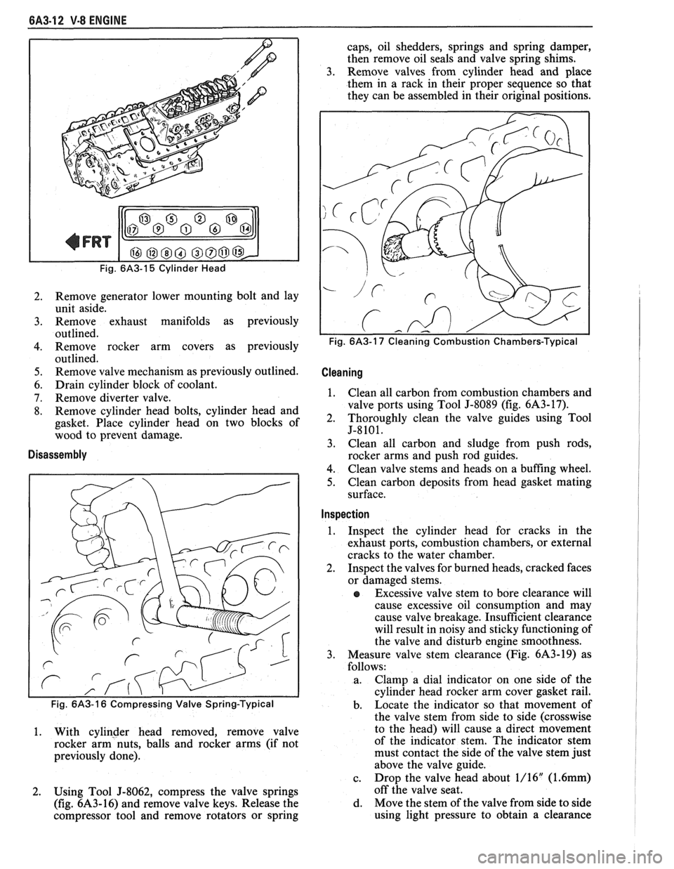
Fig. 6A3-15 Cylinder Head
2. Remove generator lower mounting bolt and lay
unit aside.
3. Remove exhaust manifolds as previously
outlined.
4. Remove rocker arm covers as previously
outlined.
5. Remove valve mechanism as previously outlined.
6. Drain cylinder block of coolant.
7. Remove diverter valve.
8. Remove cylinder head bolts, cylinder head and
gasket. Place cylinder head on two blocks of
wood to prevent damage.
Disassembly
1. With cylinder head removed, remove valve
rocker arm nuts, balls and rocker arms (if not
previously done).
2. Using Tool
5-8062, compress the valve springs
(fig.
6A3-16) and remove valve keys. Release the
compressor tool and remove rotators or spring caps, oil shedders,
springs and spring damper,
then remove oil seals and valve spring shims.
3. Remove valves from cylinder head and place
them in a rack in their proper sequence so that
they can be assembled in their original positions.
Cleaning I
1. Clean all carbon from combustion chambers and
valve ports using Tool J-8089 (fig.
6A3-17).
2. Thoroughly clean the valve guides using Tool
5-8101.
3. Clean
all carbon and sludge from push rods,
rocker arms and push rod guides.
4. Clean valve stems and heads on a buffing wheel.
5. Clean carbon deposits from head gasket mating
surface.
Inspection I
1. Inspect
the cylinder head for cracks in the
exhaust ports, combustion chambers, or external
cracks to the water chamber.
2. Inspect the valves for burned heads, cracked faces
or damaged stems.
e Excessive valve stem to bore clearance will
cause excessive oil consumption and may
cause valve breakage. Insufficient clearance
will result in noisy and sticky functioning of
the valve and disturb engine smoothness.
3. Measure valve stem clearance (Fig. 6A3-19) as
follows:
a. Clamp a dial indicator
on one side of the
cylinder head rocker arm cover gasket rail.
b. Locate
the indicator so that movement of
the valve stem from side to side (crosswise
to the head) will cause a direct movement
of the indicator stem. The indicator stem
must contact the side of the valve stem just
above the valve guide.
c. Drop
the valve head about 1/16"
(1.6mm)
off the valve seat.
d. Move the stem of the valve from side to side
using light pressure to obtain a clearance