1988 PONTIAC FIERO engine oil
[x] Cancel search: engine oilPage 360 of 1825
2.8 LITER V-6 6A2-9
INTAKE MANIFOLD (FIGURE 6A2-7)
Removal
Disconnect battery.
Remove air cleaner.
Drain coolant.
Refer to Section 6E3 for removal of the following
PFI sub-assemblies.
e Plenum
e Fuel Rail
e Runner
Disconnect spark plug wires at spark plugs.
Disconnect wires at coil.
Remove distributor cap and spark plug wires.
Mark distributor position and remove hold down
bracket.
Remove distributor.
Remove air management hose, manual
transmission only.
Disconnect emission canister hoses. Remove pipe
bracket (front left valve cover).
Remove left valve cover.
Remove air management bracket, manual
transmission only.
Remove right valve cover.
Remove upper radiator hose.
Disconnect heater hose.
Disconnect coolant switches.
Remove manifold bolts.
Remove manifold. Discard manifold gaskets and
remove loose RTV from front and rear ridges of
cylinder case.
Installation
When installing intake gaskets, notice that the
gaskets are marked Right Side and Left Side
(carbureted only). Use them only as indicated to
maintain designed efficiency of this engine.
1. Make
sure that no oil or water is present on
surface when new RTV is applied. Place a 5mm
diameter
(3/16") bead of RTV, # 1052917 or
equivalent, on each ridge.
2. Install
new intake gaskets on cylinder heads.
Hold in place by extending ridge RTV bead up
6mm onto the gasket ends. The new intake
gaskets will have to be cut, where indicated, to
install behind push rods. Cut only those areas
that are necessary.
3. Install intake
manifold on engine. Make sure
areas between case ridges and intake are
completely sealed.
4. Install manifold retaining bolts and nuts and
torque in the sequence shown in Figure 6A2-7.
5. Install heater and radiator hose to manifold.
6. Install rocker covers as previously outlined.
7. Connect coolant switches.
8. Install air management bracket.
9. Install pipe bracket (front left rocker cover).
10. Install distributor, distributor cap and retaining
nut. Do not tighten.
11. Refer to Section 6E3 for installation of PFI
sub-assemblies removed. 12.
Connect
necessary wires and hoses.
13. Fill cooling system with
the proper mixture of
ethylene glycol anti-freeze and water. Do not
install radiator cap.
14. Start
engine, set intitial timing. After set, torque
distibutor hold down clamp bolt to 34
N-m (25
lb. ft.). Recheck timing after torquing bolt.
15. Let engine
run until radiator upper hose becomes
hot (thermostat open).
16. With
engine idling, add coolant to radiator, if
necessary, until level reaches bottom of filler
neck.
17. Install
radiator cap, making sure arrows on cap
line up with overflow tube.
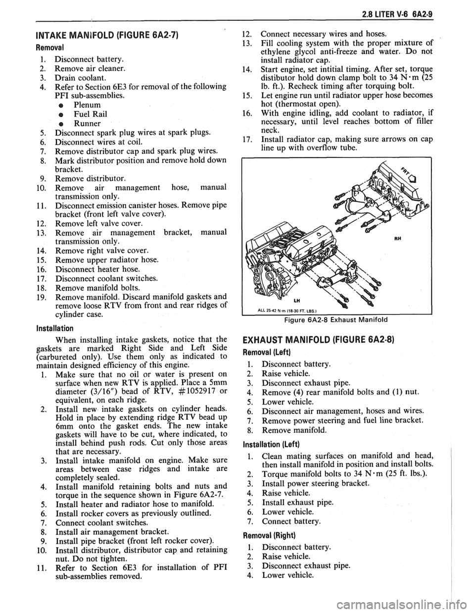
Figure 6A2-8 Exhaust Manifold
EXHAUST MANIFOLD (FIGURE 6A2-8)
Removal (Left)
1. Disconnect battery.
2. Raise vehicle.
3. Disconnect exhaust pipe.
4. Remove
(4) rear manifold bolts and (1) nut.
5. Lower vehicle.
6. Disconnect air management, hoses and wires.
7. Remove power steering and fuel line bracket.
8. Remove manifold.
Installation (Left)
1. Clean mating surfaces on manifold and head,
then install manifold in position and install bolts.
2. Torque
manifold bolts to 34
N.m (25 ft. lbs.).
3. Install power steering bracket.
4. Raise vehicle.
5. Install exhaust pipe.
6. Lower vehicle.
7. Connect battery.
Removal (Right)
1. Disconnect battery.
2. Raise vehicle.
3. Disconnect exhaust pipe.
4. Lower vehicle.
Page 361 of 1825
6A2-10 2.8 LITER V-6
5. Remove air management valve from A.I.R.
pump. 6. Remove alternator bracket.
7. Remove exhaust manifold bolts.
8. Disconnect air management hose.
9. Remove manifold.
Installation (Right)
1. Clean
mating surfaces on manifold and head,
then install manifold in position and install bolts.
2. Torque
manifold bolts to 34
N-m (25 ft. lbs.).
3. Attach air management hose.
4. Raise vehicle.
5. Install exhaust pipes.
6. Lower vehicle.
7. Install alternator bracket.
8. Install air management valve.
7. Connect battery.
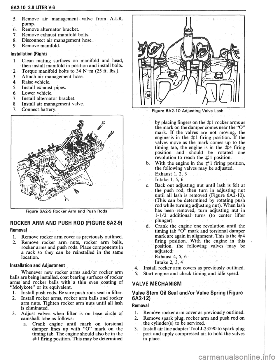
Figure 6A2-9 Rocker Arm and Push Rods
ROCKER ARM AND PUSH ROD (FIGURE 6A2-9)
Removal
1. Remove
rocker arm cover as previously outlined.
2. Remove rocker arm nuts, rocker arm balls,
rocker arms and push rods. Place components in
a rack so they can be reinstalled in the same
location.
lnstallation and Adiustment
Whenever new rocker arms and/or rocker arm
balls are being installed, coat bearing surfaces of rocker
arms and rocker balls with a thin even coating of
"Molykote" or its equivalent.
1. Install push rods. Be sure push rods seat in lifter.
2. Install rocker arms, rocker arm balls and rocker
arm nuts. Tighten rocker arm nuts until all lash
is eliminated.
3. Adjust valves when lifter is on base circle of
camshaft lobe as follows:
a. Crank engine until mark on torsional
damper lines up with
"0" mark on the
timing tab. The engine should also be in the
# 1 firing position. This may be determined
Figure 6A2-10 Adjusting Valve Lash
by placing fingers on the # 1 rocker arms as
the mark on the damper comes near the
"0"
mark. If the valves are not moving, the
engine is in the
# 1 firing position. If the
valves move as the mark comes up to the
timing tab, the engine is in the
#4 firing
position and should be rotated one
revolution to reach the
# 1 position.
b. With the
engine in the
# 1 firing position,
the following valves may be adjusted.
Exhaust 1, 2, 3
Intake 1, 5,
6
c. Back
out adjusting nut until lash is felt at
the push rod, then turn in adjusting nut
until all lash is removed (Figure
6A2-10).
(This can be determined by rotating push
rod while turning adjusting nut). When lash
has been removed, turn adjusting nut in
1-1/2 additional turns (to center lifter
plunger).
d. Crank the
engine one revolution until the
timing tab
"0" mark and torsional damper
mark are again in alignment. This is the
#4
firing position. With the engine in this
position, the following valves may be
adjusted:
Exhaust 4, 5,
6
Intake 2, 3, 4
4.
Install rocker arm covers as previously outlined.
5. Start
engine and check timing and idle speed.
VALVE MECHANISM
Valve Stern Oil Seal and/or Valve Spring (Figure
6A2-12)
Removal
1. Remove rocker
arm cover as previously outlined.
2. Remove spark plug, rocker arm and push rod on
the
cylinder(s) to be serviced.
3. Install
air line adapter Tool J-23590 to spark plug
port and apply compressed air to hold the valves
in place.
Page 362 of 1825
2.8 LITER V-6 8A2-11
ENGAGE AT
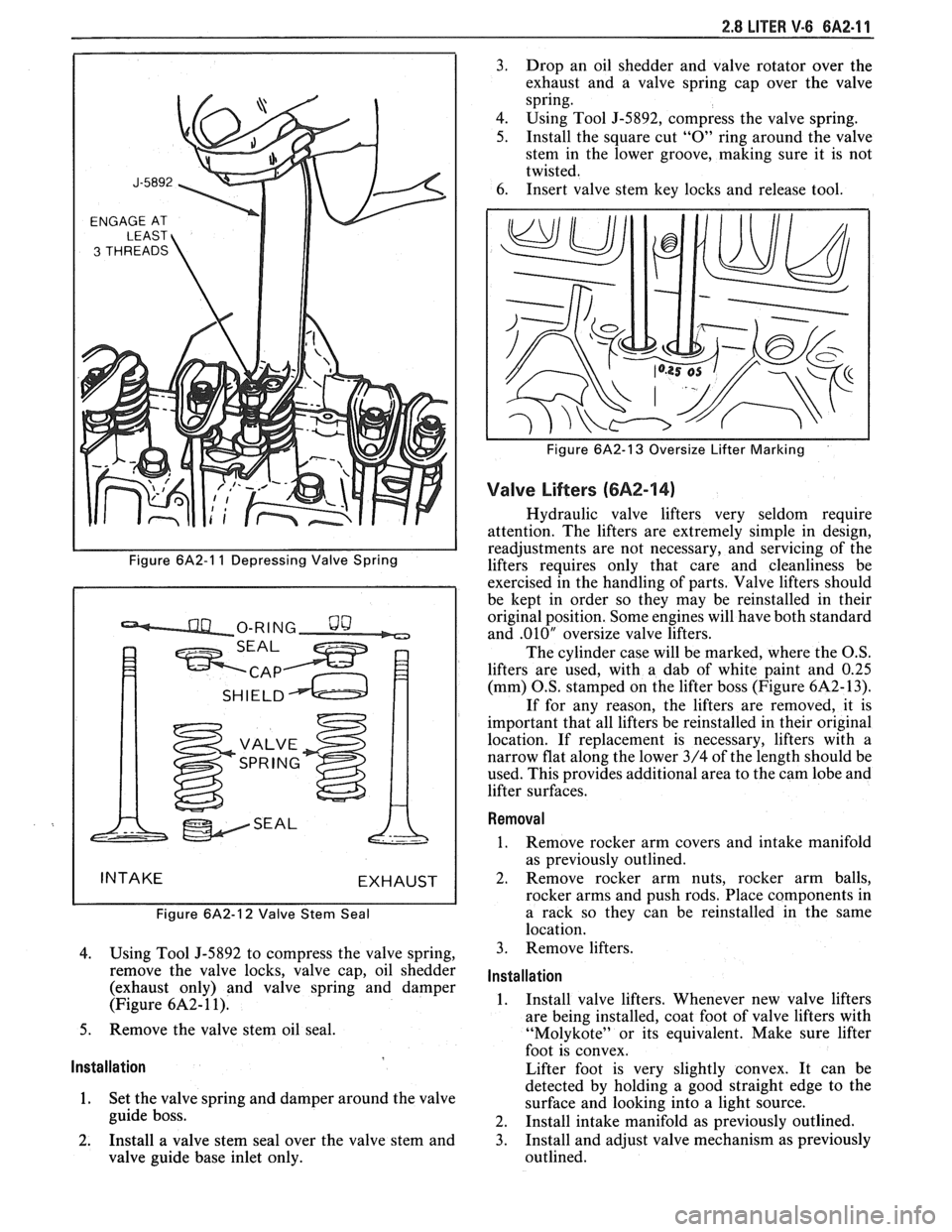
Figure 6A2-1 1 Depressing Valve Spring
Figure
6A2-12 Valve Stem Seal
4. Using Tool J-5892 to compress the valve spring,
remove the valve locks, valve cap, oil shedder
(exhaust only) and valve spring and damper
(Figure
6A2- 1 1).
5. Remove the valve stem oil seal.
Installation
1. Set the valve spring and damper around the valve
guide boss.
2. Install a valve stem seal over the valve stem and
valve guide base inlet only. 3.
Drop an oil shedder and valve rotator over the
exhaust and a valve spring cap over the valve
spring.
4. Using Tool
5-5892, compress the valve spring.
5. Install the square cut "0" ring around the valve
stem in the lower groove, making sure it is not
twisted.
6. Insert valve stem key locks and release tool.
Figure 6A2-13 Oversize Lifter Marking
Valve Lifters (6A2-14)
Hydraulic valve lifters very seldom require
attention. The lifters are extremely simple in design,
readjustments are not necessary, and servicing of the
lifters requires only that care and cleanliness be
exercised in the handling of parts. Valve lifters should
be kept in order so they may be reinstalled in their
original position. Some engines will have both standard
and
.010" oversize valve lifters.
The cylinder case will be marked, where the O.S.
lifters are used, with a dab of white paint and
0.25
(mm) O.S. stamped on the lifter boss (Figure 6A2- 13).
If for any reason, the lifters are removed, it is
important that all lifters be reinstalled in their original
location. If replacement is necessary, lifters with a
narrow flat along the lower 3/4 of the length should be
used. This provides additional area to the cam lobe and
lifter surfaces.
Removal
1. Remove rocker arm covers and intake manifold
as previously outlined.
2. Remove rocker arm nuts, rocker arm balls,
rocker arms and push rods. Place components in
a rack so they can be reinstalled in the same
location.
3. Remove lifters.
Installation
1. Install valve lifters. Whenever new valve lifters
are being installed, coat foot of valve lifters with
"Molykote" or its equivalent. Make sure lifter
foot is convex.
Lifter foot is very slightly convex. It can be
detected by holding a good straight edge to the
surface and looking into a light source.
2. Install intake manifold as previously outlined.
3. Install and adjust valve mechanism as previously
outlined.
Page 363 of 1825
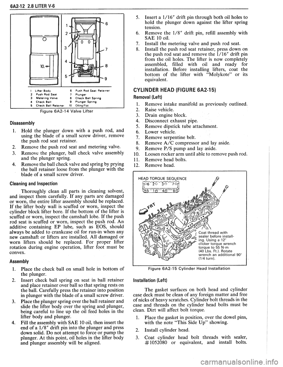
I Liher Body 6 Push Rod Seat Reta~ner 2 Push Rod Seal 7 Plunger 3 Mater~ng Valve 8 Check Ball Spr~ng 4 Check Ball 9 Plunger Spr~ng 5 Check Ball Rete~ner 10 Olllna Flat
Figure 6A2-14 Valve Lifter
Disassembly
1. Hold the plunger down with a push rod, and
using the blade of a small screw driver, remove
the push rod seat retainer.
2. Remove the push rod seat and metering valve.
3. Remove the plunger, ball check valve assembly
and the plunger spring.
4. Remove the ball check valve and spring by prying
the ball retainer loose from the plunger with the
blade of a small screw driver.
Cleaning and Inspection
Thoroughly clean all parts in cleaning solvent,
and inspect them carefully. If any parts are damaged
or worn, the entire lifter assembly should be replaced.
If the lifter body wall is scuffed or worn, inspect the
cylinder block lifter bore. If the bottom of the lifter is
scuffed or worn, inspect the camshaft lobe. If the push
rod seat is scuffed or worn, inspect the push rod. An
additive containing EP lube, such as EOS, should
always be added to crankcase oil for run-in when any
new camshaft or lifters are installed. All damaged or
worn lifters should be replaced. For proper lifter
rotation during engine operation, lifter foot must be
convex.
Assembly
1. Place
the check ball on small hole in bottom of
the plunger.
2. Insert
check ball spring on seat in ball retainer
and place retainer over ball so that spring rests on
the ball. Carefully press the retainer into position
in plunger with the blade of a small screw driver.
3. Place the plunger spring over the ball retainer and
slide the lifter body over the spring and plunger,
being careful to line up the oil feed holes in the
lifter body and plunger.
4. Fill the assembly with SAE 10 oil, then insert the
end of a
1/8" drift pin into the plunger and press
down solid. Do not attempt to force or pump the
plunger. At this point, oil holes in the lifter body
and plunger assembly will be aligned.
5. Insert a 1/16" drift pin through both oil holes to
hold the plunger down against the lifter spring
tension.
6. Remove
the
1/8" drift pin, refill assembly with
SAE 10 oil.
7. Install the metering valve and push rod seat.
8. Install the push rod seat retainer, press down on
the push rod seat and remove the 1/16" drift pin
from the oil holes. The lifter is now completely
assembled, filled with oil and ready for
installation. Before installing lifters, coat the
bottom of the lifter with "Molykote" or its
equivalent.
CYLINDER HEAD (FIGURE 6A2-15)
Removal (Left)
Remove intake manifold as previously outlined.
Raise vehicle.
Drain engine block.
Disconnect exhaust pipe.
Remove dipstick tube attachment.
Lower vehicle.
Remove serpentine belt.
Remove A/C compressor and lay aside.
Remove
P/S pump and lay aside.
Loosen rocker arm until able to remove push rod.
Remove head bolts.
Remove head.
HEAD TORQUE SEQUENCE
/7 , 2 ing. Using a 12"
Figure 6A2-1'5 Cylinder Head Installation
Installation (Left)
The gasket surfaces on both head and cylinder
case deck must be clean of any foreign matter and free
of nicks of heavy scratches. Cylinder bolt threads in the
case and threads on the cylinder head bolts must be
clean. Dirt will affect bolt torque.
1. Place the gasket in position, over the dowel pins,
with the note "This Side Up" showing.
2. Install cylinder head.
3. Coat cylinder head bolt threads with sealer,
#1052080 or equivalent, and install bolts.
Page 364 of 1825
2.8 LITER V.6 6A2.13
Torque bolts as shown in Figure 6A2-15.
4. Install
push rods and loosely retain with rocker
arms. Make sure lower ends of
pushrods are in
lifter seats.
5. Install intake manifold.
6. Raise vehicle.
7. Install dipstick tube bracket.
8. Connect exhaust pipe
to exhaust manifold flange.
9. Lower vehicle.
10. Adjust
valve lash as previously outlined.
11. Continue
following intake manifold installation
for build up.
Removal (Right)
Remove intake manifold as previously outlined.
Raise vehicle.
Disconnect exhaust pipe.
Drain engine block.
Lower vehicle.
Loosen rocker arms until able to remove push
rod.
Remove serpentine belt.
Remove tensioner.
Remove A.I.R. bracket.
Remove generator bracket.
Remove head bolts.
Remove head.
Installation (Right)
The gasket surfaces on both the head and cylinder
case
deck must be clean of any foreign matter and free
of nicks of heavy scratches. Cylinder bolt threads in the
case and threads on the cylinder head bolts must be
clean. Dirt will affect bolt torque.
1. Place the gasket in position, over the dowel pins,
with the note "This Side Up" showing.
2. Install cylinder head.
3. Coat cylinder head bolt threads with sealer,
#lo52080 or equivalent, and install bolts.
Torque bolts as shown in (Figure
6A2-15).
Install push rods and loosely retain with rocker
arms. Make sure lower ends of push rods are in
lifter seats.
Install intake manifold.
Raise vehicle.
Install exhaust pipe to exhaust manifold flange.
Lower vehicle.
Adjust valve lash as previously outlined.
Install AIR bracket.
Install tensioner.
Install generator bracket.
Continue following intake manifold installation
for build up.
Disassembly
1. With cylinder head removed, remove rocker arm
nuts, balls and rocker arms (if not previously
done).
2. Using tool J-8062, compress the valve springs and
remove valve keys. Release the compressor tool and
remove spring caps, oil shedders, springs and
damper assemblies, then remove oil seals.
3. Remove valves from cylinder head and place
them in a rack so they can be installed in their
original positions.
Cleaning and Inspection
Clean all carbon from combustion chambers and
valve ports using 'tool
5-8089.
Thoroughly clean valve guides using 5-8 10 1.
Clean all carbon and sludge from push rods,
rocker arms and push rod guides.
Clean valve stems and heads on a buffing wheel.
Clean carbon deposits from head gasket mating
surface.
Inspect cylinder head for cracks in the exhaust
ports, combustion chambers, or external cracks
to the water jacket.
Inspect the valves for burned heads, cracked faces
or damaged stems.
NOTICE: Excessive valve stem to bore clearance
will cause high oil consumption and may cause
valve breakage. Insufficient clearance will result in
noise and sticky functioning of the valve and
disturb engine smoothness.
8. Measure valve stem clearance as follows:
a. Clamp
a dial indicator on one side of the
cylinder head. Locate the indicator so that
movement of the valve stem from side to
side (crosswise to the head) will cause direct
movement of the indicator stem. The
indicator stem must contact the side of the
valve stem just above the guide.
b. Drop
the valve head
1.5mm off the valve
seat.
c. Move
the stem of the valve from side to side,
using light pressure, to obtain a clearance
reading. If clearance exceeds specifications,
it will be necessary to ream valve guides for
oversize valves. Service valves are available
in std., 089,
.394 and .775mm O.S. sizes.
9. Check
valve spring tension with tool J-8056,
spring tester. Springs should be compressed to the
specified height and checked against the
specifications chart. Springs should be replaced if
not within 44
N (10 Ibs.) of the specified load
(without dampers).
10. Inspect
rocker arm studs for wear or damage.
ROCKER ARM STUDS
Cylinder heads use threaded rocker arm studs.
Rocker arm studs that have damaged threads should
be replaced with new studs. If, for some reason, the
threads in the head
are damaged or stripped, the head
can be retapped, and a helical type insert added. If such
an insert is not available, the head should be replaced.
VALVE GUIDES
Valves with oversize stems are available in .089,
,394 and ,775mm over sizes. To ream the valve guide
Page 365 of 1825
BA2-14 2.8 LITER V-6
bores for oversize valves use tool 5-5330-1, 2 or 3,
respectively.
VALVE SEATS
Reconditioning the valve seats is very important,
because the seating of the valves must be perfect for the
engine to deliver the power and performance designed
into it.
Another important factor is the cooling of the
valve heads. Good contact between each valve and its
seat in the head is imperative to insure that the heat in
the valve head will be properly carried away.
Several different types of equipment are available
for reseating valve seats. The recommendations of the
manufacturer of the equipment being used should be
carefully followed to attain proper results.
VALVES
Valves that are pitted can be refaced, to the
proper angle, insuring correct relation between the
head and stem, on a valve
refacing machine. Valve
stems which show excessive wear, or valves that are
warped excessively should be replaced. When a valve
head which is warped excessively is
refaced, a knife
edge will be ground on part or all of the valve head due
to the amount of metal that must be removed to
completely
reface the valve. Knife edges lead to
breakage, burning or preignition due to heat localizing
on this knife edge. If the edge of the valve head is less
than
.8mm thick after grinding, replace the valve.
Several different types of equipment are available
for
refacing valves. The recommendations of the
manufacturer of the equipment being used should be
carefully followed to attain the proper results.
Assembly
Insert a valve in the proper port.
Install a valve stem seal over the valve stem and
valve guide base inlet only.
Drop an oil shedder and valve rotator over the
exhaust and a valve spring cap over the valve
spring.
Using tool
5-8062 compress the valve spring.
Install the square cut
"0" ring around the valve
stem in the lower groove, making sure it is not
twisted.
Insert valve, stem key locks and release tool.
Install the valve locks and release the compressor
tool making sure that the locks seat properly in
the upper groove of the valve stem. Grease may
be used to hold the locks in place while releasing
the compressor tool.
Install the remaining valves.
Check each valve stem oil seal by placing valve
stem leak detector, tool J-23994, over the end of
the valve stem and against the cap. Operate the
vacuum pump and make sure no air leaks pass the
seal.
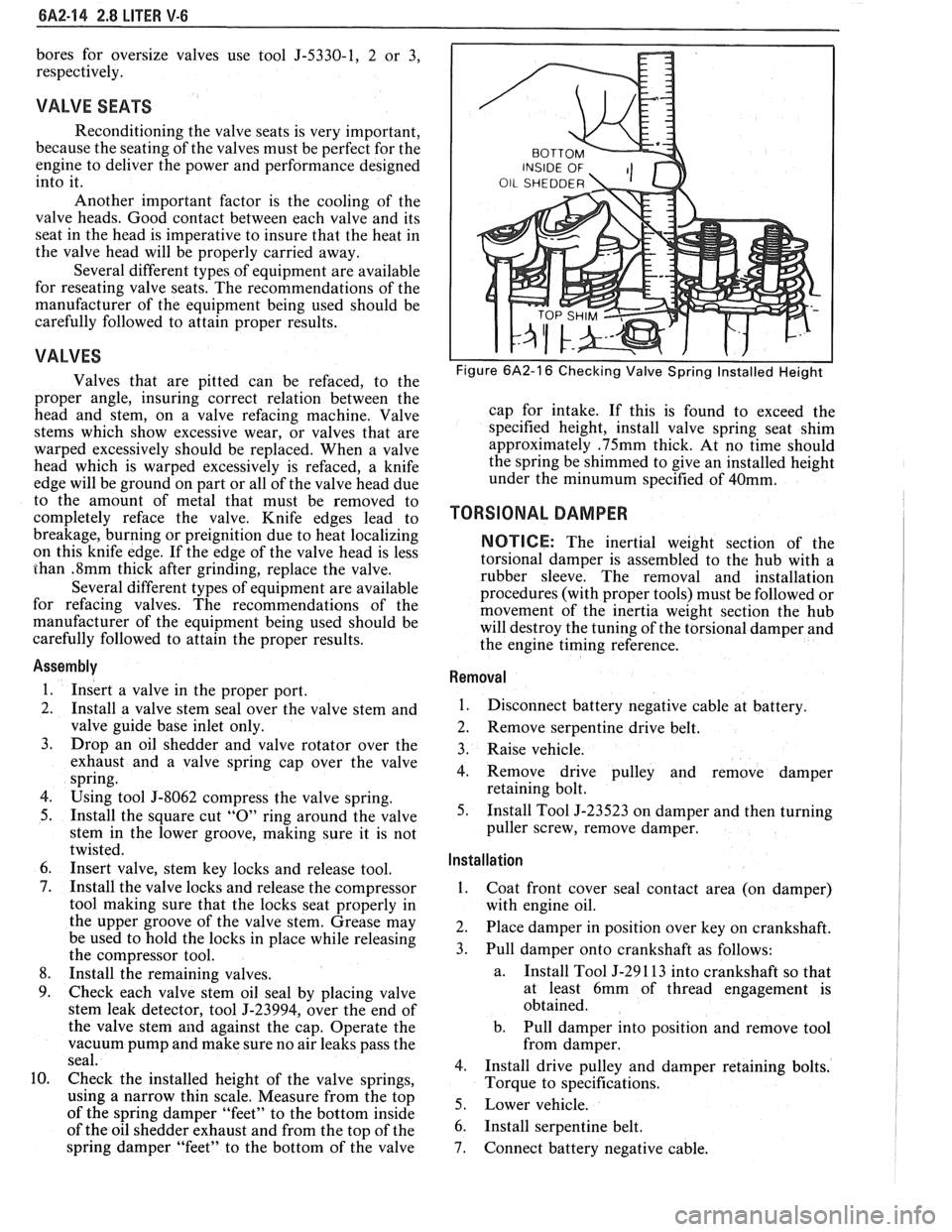
Check the installed height of the valve springs,
using
a narrow thin scale. Measure from the top
of the spring damper "feet" to the bottom inside
of the oil shedder exhaust and from the top of the
spring damper "feet" to the bottom of the valve
Figure 6A2-16 Checking Valve Spring Installed Height
cap for intake. If this is found to exceed the
specified height, install valve spring seat shim
approximately
.75mm thick. At no time should
the spring be shimmed to give an installed height
under the
minumum specified of 40mm.
TORSIONAL DAMPER
NOTICE: The inertial weight section of the
torsional damper is assembled to the hub with a
rubber sleeve. The removal and installation
procedures (with proper tools) must be followed or
movement of the inertia weight section the hub
will destroy the tuning of the torsional damper and
the engine timing reference.
Removal
1.
Disconnect battery negative cable at battery.
2. Remove serpentine drive belt.
3. Raise vehicle.
4. Remove drive pulley and remove damper
retaining bolt.
5. Install Tool J-23523 on damper and then turning
puller screw, remove damper.
Installation ,
1.
Coat front cover seal contact area (on damper)
with engine oil.
2. Place damper in position over key on crankshaft.
3. Pull damper onto crankshaft as follows:
a. Install
Tool J-29 1 13 into crankshaft so that
at least 6mm of thread engagement is
obtained.
b. Pull damper into position and remove tool
from damper.
4. Install drive pulley and damper retaining bolts.
Torque to specifications.
5. Lower vehicle.
6. Install serpentine belt.
7. Connect battery negative cable.
Page 366 of 1825
2.8 LITER V.6 6A2-15
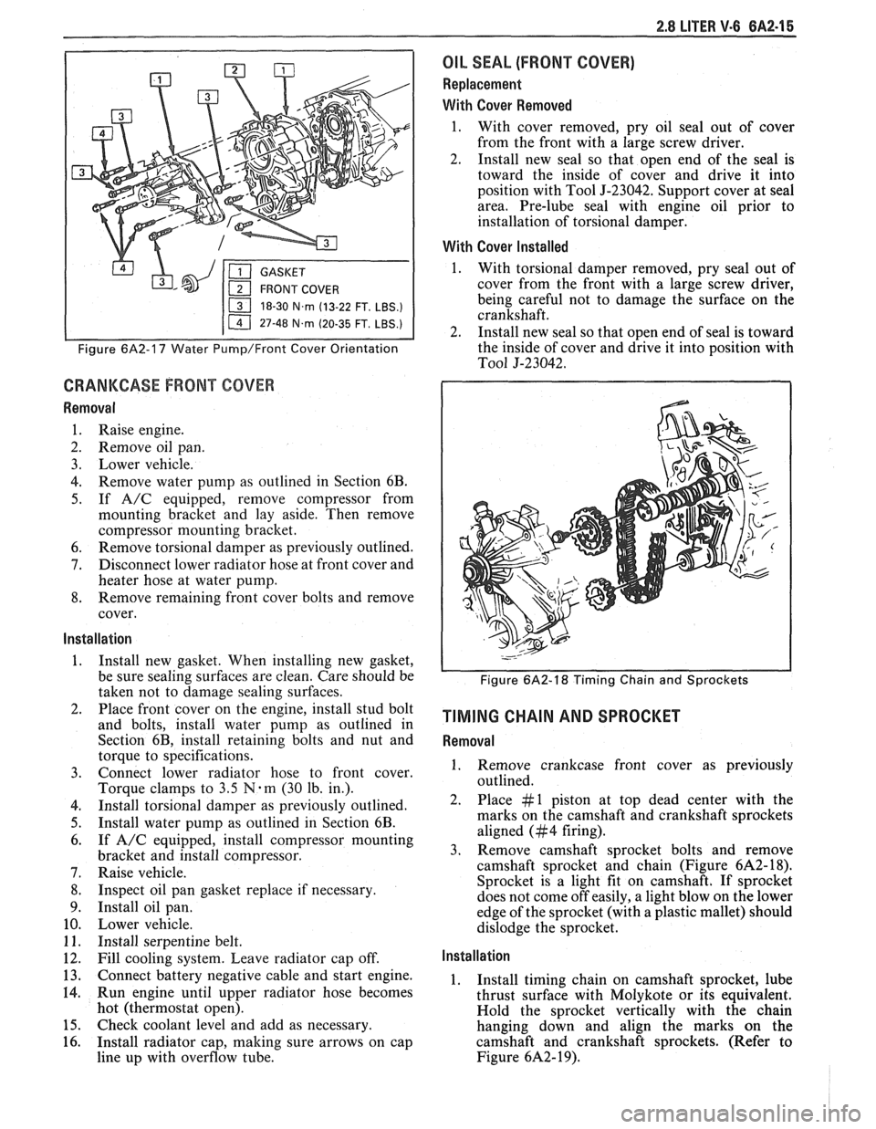
18-30 N.m (13-22 FT. LBS.)
I 11 47-48 N.m (20-35 FT. LBS.) I
Figure 6A2-17 Water Pump/Front Cover Orientation
CRANKCASE FRONT COVER
Removal
1. Raise engine.
2. Remove oil pan.
3. Lower vehicle.
4. Remove water pump as outlined in Section 6B.
5. If A/C equipped, remove compressor from
mounting bracket and lay aside. Then remove
compressor mounting bracket.
6. Remove torsional damper as previously outlined.
7. Disconnect lower radiator hose at front cover and
heater hose at water pump.
8. Remove remaining front cover bolts and remove
cover.
Installation
1. Install new gasket. When installing new gasket,
be sure sealing surfaces are clean. Care should be
taken not to damage sealing surfaces.
2. Place front cover on the engine, install stud bolt
and bolts, install water pump as outlined in
Section 6B, install retaining bolts and nut and
torque to specifications.
3. Connect lower radiator hose to front cover.
Torque clamps to
3.5 N-m (30 lb. in.).
4. Install torsional damper as previously outlined.
5. Install water pump as outlined in Section 6B.
6. If A/C equipped, install compressor mounting
bracket and install compressor.
7. Raise vehicle.
8. Inspect oil pan gasket replace if necessary.
9. Install oil pan.
10. Lower vehicle.
11. Install serpentine belt.
12. Fill cooling system. Leave radiator cap off.
13. Connect battery negative cable and start engine.
14. Run engine until upper radiator hose becomes
hot (thermostat open).
15. Check coolant level and add as necessary.
16. Install radiator cap, making sure arrows on cap
line up with overflow tube.
OIL SEAL (FRONT COVER)
Replacement
With Cover Removed
1. With cover removed, pry oil seal out of cover
from the front with a large screw driver.
2. Install new seal so that open end of the seal is
toward the inside of cover and drive it into
position with Tool
5-23042. Support cover at seal
area. Pre-lube seal with engine oil prior to
installation of torsional damper.
With Cover Installed
1. With torsional damper removed, pry seal out of
cover from the front with a large screw driver,
being careful not to damage the surface on the
crankshaft.
2. Install new seal so that open end of seal is toward
the inside of cover and drive it into position with
To01 5-23042.
Figure 6A2-18 Timing Chain and Sprockets
TIMING CHAIN AND SPROCKET
Removal
1. Remove crankcase front cover as previously
outlined.
2. Place #1 piston at top dead center with the
marks on the camshaft and crankshaft sprockets
aligned (#4 firing).
3. Remove camshaft sprocket bolts and remove
camshaft sprocket and chain (Figure
6A2- 18).
Sprocket is a light fit on camshaft.
If sprocket
does not come off easily, a light blow on the lower
edge of the sprocket (with a plastic mallet) should
dislodge the sprocket.
Installation
1. Install timing chain on camshaft sprocket, lube
thrust surface with Molykote or its equivalent.
Hold the sprocket vertically with the chain
hanging down and align the marks on the
camshaft and crankshaft sprockets. (Refer to
Figure
6A2- 19).
Page 367 of 1825
6A2-16 2.8 LITER V-6
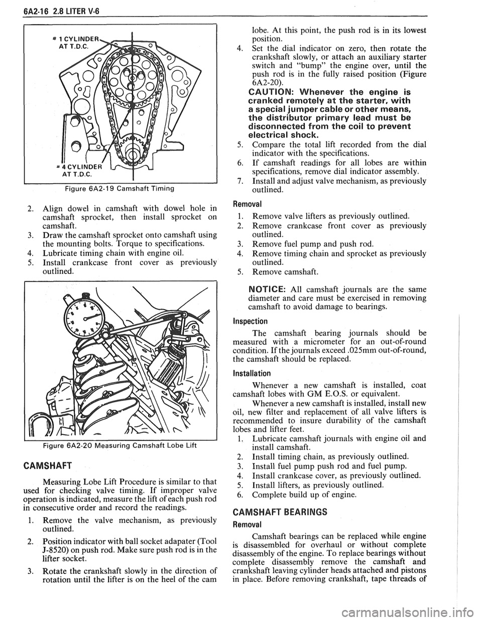
Figure 6A2-19 Camshaft Timing
2. Align dowel in camshaft with dowel hole in
camshaft sprocket, then install sprocket on
camshaft.
3. Draw the camshaft sprocket onto camshaft using
the mounting bolts. Torque to specifications.
4. Lubricate timing chain with engine oil.
5. Install crankcase front cover as previously
outlined.
Figure 6A2-20 Measuring Camshaft Lobe Lift
CAMSHAFT
Measuring Lobe Lift Procedure is similar to that
used for checking valve timing. If improper valve
operation is indicated, measure the lift of each push rod
in consecutive order and record the readings.
1. Remove the valve mechanism, as previously
outlined.
2. Position
indicator with ball socket adapater (Tool
5-8520) on push rod. Make sure push rod is in the
lifter socket.
3. Rotate the crankshaft slowly in the direction of
rotation until the lifter is on the heel of the cam lobe.
At this point, the push rod is in its lowest
position.
4. Set the dial indicator on zero, then rotate the
crankshaft slowly, or attach an auxiliary starter
switch and "bump" the engine over, until the
push rod is in the fully raised position (Figure
6A2-20).
CAUTION: Whenever the engine is
cranked remotely at the starter, with
a special jumper cable or other means,
the distributor primary lead must be
disconnected from the coil to prevent
electrical shock.
5. Compare the total lift recorded from the dial
indicator with the specifications.
6. If camshaft readings for all lobes are within
specifications, remove dial indicator assembly.
7. Install and adjust valve mechanism, as previously
outlined.
Removal
1. Remove valve lifters as previously outlined.
2. Remove crankcase front cover as previously
outlined.
3. Remove fuel pump and push rod.
4. Remove timing chain and sprocket as previously
outlined.
5. Remove camshaft.
NOTICE: All camshaft journals are the same
diameter and care must be exercised in removing
camshaft to avoid damage to bearings.
Inspection
The camshaft bearing journals should be
measured with a micrometer for an out-of-round
condition. If the journals exceed
.025mm out-of-round,
the camshaft should be replaced.
Installation
Whenever a new camshaft is installed, coat
camshaft lobes with
GM E.O.S, or equivalent.
Whenever a new camshaft is installed, install new
oil, new filter and replacement of all valve lifters is
recommended to insure durability of the camshaft
lobes and lifter feet.
1. Lubricate camshaft journals with engine oil and
install camshaft.
2. Install timing chain, as previously outlined.
3. Install fuel pump push rod and fuel pump.
4. Install crankcase cover, as previously outlined.
5. Install
lifters, as previously outlined.
6. Complete build up of engine.
CAMSHAFT BEARINGS
Removal
Camshaft bearings can be replaced while engine
is disassembled for overhaul or without complete
disassembly of the engine. To replace bearings without
complete disassembly remove the camshaft and
crankshaft leaving cylinder heads attached and pistons
in place. Before removing crankshaft, tape threads of