1988 PONTIAC FIERO engine oil
[x] Cancel search: engine oilPage 46 of 1825
AIR CONDITIONING 1 B-3
A low-side pressure Schrader valve service fit-
ting is located near the top of the accumulator. A
similar Schrader fitting may be provided for mounting
the pressure cycling switch. It is not necessary to dis-
charge the system to replace the switch. The accumu-
lator is serviced only as a replacement assembly.
Heater Core
The heater core heats the air before it enters the
car. Engine coolant is circulated through the core to
heat the outside air passing over the fins of the core.
The core is functional at all times (no water valve) and
may be used to temper conditioned air in
A/C mode,
as well as heat or vent mode.
SYSTEM COMPONENTS --- CON"FOL
Controller
The operation of the A/C system is controlled by
the switches and the lever on the control head. The
compressor clutch and blower are connected electri-
cally to the control head by a wiring harness. The
blower circuit is open in the off mode and air flow is
provided by the four blower speeds available in the
remaining modes. Cooled and dehumidified air is
available in the max, normal, bi-level and defrost
modes.
Temperature is controlled by the position of the
temperature lever on the control head. A cable con-
nects this lever to the temperature door which controls
air flow through the heater core. As the temperature
lever is moved through its range of travel, a sliding
clip on the cable at the temperature valve connection
should assume a position assuring that the temperature
door will seat in both extreme positions. Temperature
door position is independent of mode selection. The
temperature cable attaches to the right side of the air
conditioning module. The temperature door on some
models is controlled electrically, thereby eliminating
the need for the temperature cable.
The electric engine cooling fan on some cars is
not part of the
A/C system; however, the fan is
operational any time the
A/C control is in Max.,
Norm, or Bi-Level modes. Some models provide for
engine cooling fan operation when the controller is in
the defrost mode. This added feature is part of the
A/C
controller function and is aimed at preventing exces-
sive compressor head temperatures. It also allows the
A/C system to function more efficiently. On some
models during road speed (above
35 mph) conditions
when air flow through the condenser coil is adequate
for efficient cooling, the engine cooling fan will be
turned off. The operation of the cooling fan is con-
trolled by the ECM through the cooling fan relay.
Complete wiring diagrams and diagnosis for the
AIC Electrical System are in Section 8A. Section 8A
also contains additional diagnostic information
regarding air flows and vacuum logic.
Vacuum Lines
Vacuum lines are molded to a connector which
is attached to a vacuum control switch on the control
head assembly.
In case of leakage or hose collapse, it will not be
necessary to replace the entire harness assembly.
Replacement can be made by cutting the hose and
inserting a plastic connector. If an entire hose must be
replaced, cut all hoses off at the connector and then
attach hoses directly to the control head vacuum
switch. (NOTE: The Fiero uses an electric motor to
control mode selection. Therefore, it will not have a
vacuum harness.
)
Vacuum Tank
During heavy acceleration, the vacuum supply
from the carburetor drops. A check valve in the vac-
uum tank maintains vacuum so that, under load condi-
tions, vacuum will be available for continuous use.
REWVS AND SWITCHES
High-Pressure Compresssr Gut-OFF Switch
The high-side, high-pressure cut-off switch in
the rear head of the compressor is a protective device
intended to prevent excessive compressor head pres-
sures and reduce the chance of refrigerant escape
through a safety relief valve. Normally closed, this
switch will open the circuit at a high-side pressure of
approximately 2700
kPa (430 psi 9 20 psi) and
reclose the circuit at approximately 1379 kPa (200 psi
9 50 psi).
Lsw-Pressure Cut-On Switch
Compressor protection is provided on some cars
by a low-pressure cut-off switch which will open in
the event of a low-charge condition. This switch can
be located in the liquid line or in the rear head of the
compressor. This switch will also keep the compres-
sor from running during cold weather.
Pressure eyesing Switch
The refrigeration cycle (on and off operation of
the compressor) is controlled by a switch which
senses the low-side pressure as an indicator of evapo-
rator temperature. The pressure cycling switch is the
freeze protection device in the system and senses
refrigerant pressure on the suction side of the system.
This switch is located on a standard Schrader-type
valve low-side fitting. This switch also provides com-
pressor cut-off during cold weather.
Additional compressor protection results from
the operating characteristics of the low-side pressure
cycling system. If a massive discharge occurs or the
orifice tube becomes plugged, low-side pressures
could be insufficient to close the contacts of the pres-
sure switch. In the event of a low charge, insufficient
cooling accompanied by rapid compressor clutch
cycling will be noticed at high air temperatures.
Page 47 of 1825

18-4 AIR CONDITIONING
If replacement of the pressure cycling switch is
necessary, it is important to note that this may be done
without removing the refrigerant charge.
A Schrader-
type valve is located in the pressure switch fitting.
During replacement of the pressure switch, a new
oiled O-ring must be installed and the switch assem-
bled to the specified torque of
6- 13 N*m (5- 10 lb. ft.).
Power Steering Gut-OH, or Anticipate
Switch
Engine idle quality on some cars is maintained
by cutting off the compressor (switch normally
closed) when high power steering loads are imposed.
On other cars the switch (normally open) provides a
signal to the ECM to allow engine control systems to
compensate for high-power steering loads.
Wide-Open Tkroale (WOT) Compressor
Cut-Out
Switch
A switch located on the throttle corltrols of some
carburetor equipped cars opens the circuit to the com-
pressor clutch during full throttle acceleration. The
switch activates a relay that controls the compressor
clutch. During full throttle acceleration
on cars
equipped with TBI or
Em, the TPS sends a signal to
the ECM, thereby controlling the compressor clutch.
Air Conditioning Time Delay Relay
This relay on some cars controls the current to
the entire air conditioning system and provides a short
delay of air conditioning operation upon start-up.
Constant Run Relay
Engine idle quality on some cars is maintained
by a "constant run" system (constant run relay) that
eliminates compressor cycling during engine idle for a
predetermined time after the vehicle has come to rest
from road speed.
If the idle period continues for an
extended time, the
A/C system may return to a con-
ventional C.C.O.T. mode for a short time to prevent
system freeze-up. The
A/C control relay and constant
run relays are both controlled by the Electronic Con-
trol Module (ECM) which determines operating con-
ditions by evaluating input from the distributor
(engine speed), vehicle speed sensor, air sensor and
A/C compressor "on" signal.
5-PRESSURE CYCLING 8-EXPANSION TUBE
SWITCH (ORIFICE)
6-DESSICANT BAG O-LIQUID LINE
7-OIL BLEED HOLE
10-PRESSURE RELIEF
VALVE
@ ee LOW PRESSURE LIQUID HIGH PRESSURE LIQUID LOW PRESURE VAPOR HIGH PRESSURE VAPOR
Figure 2 A/C System - Typical
Page 67 of 1825
1B-24 AIR CONDPTIBNING
EVAPORATOR CORE
Remove QP Disconnect
1. Discharge A/C system.
2. Remove accumulator.
3. Remove two (2) screws and remove hi-blower
relay terminal.
4. Remove upper case screws.
5. Relocate wiring harness and remove dipstick.
6. Disconnect liquid line fitting.
7. Remove upper case and lift evaporator core out
of case (retain foam wedge).
Install or Connect
1. Reverse removal procedure to reinstall.
2. Recharge and test system for proper operation.
EVAPBRAWORCASE
Remove or Disconnect
1. Remove accumulator.
2. Remove blower motor.
3. Remove evaporator core.
Remove lower case to cowl screws (three driven from engine compartment, three driven from
interior).
Remove case from cowl.
Install or Connect
Reverse removal procedure to reinstall. Rein-
stall or replace gaskets, seal and sealant
removed during disassembly.
Recharge and test system for proper operation.
NG COMPRESSOR (TYPICAL)
Remove or Disconnect
1. Discharge A/C system.
2. Remove fitting block (coupled hose assembly)
bolt at rear of compressor.
3. Remove mounting bracket bolt(s) .
4. Remove drive belt (route lower loop behind har-
monic balancer to gain additional slack if
required).
5. Remove compressor. If complete compressor is
to be replaced, transfer usable switches, etc. to
new compressor.
Install or Connect
1. Reverse removal
procedure to reinstall. Use
new O-rings lubricated with
525 viscosity
refrigerant oil. Refer to Section
6B for drive belt
tension.
2. Evacuate and recharge system.
CONDENSER
a Remove or Disconnect
1. Discharge A/C system.
2. Disconnect coupled hose and liquid line fittings.
3, Remove screws retaining top radiator shield.
4. Remove top condenser retaining screws.
5. Carefully move (tilt) radiator rearward and lift
condenser out of radiator support.
6. Transfer brackets and mounts to new condenser
if replacement is necessary.
Install or Connect
1. Reverse removal procedure to reinstall. Use
new O-rings lubricated with
525 viscosity
refrigerant oil.
2. Recharge and test system for proper operation.
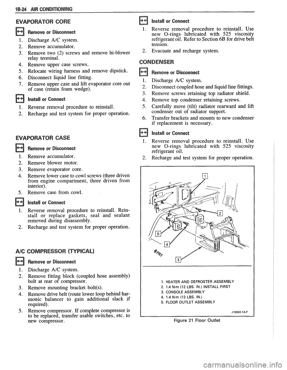
1. HEATER AND DEFROSTER ASSEMBLY
2. 1.4
N.m (12 LBS. IN.) INSTALL FIRST
3. CONSOLE ASSEMBLY
4.
1.4 Narn (12 LBS. IN.)
5. FLOOR OUTLET ASSEMBLY
Figure 21 Floor Outlet
Page 265 of 1825
4B1-12 REAR AXLE
NOTICE: Mark differential case halves with
alignment mark before disassembly because they
could be assembled
180" off from original position.
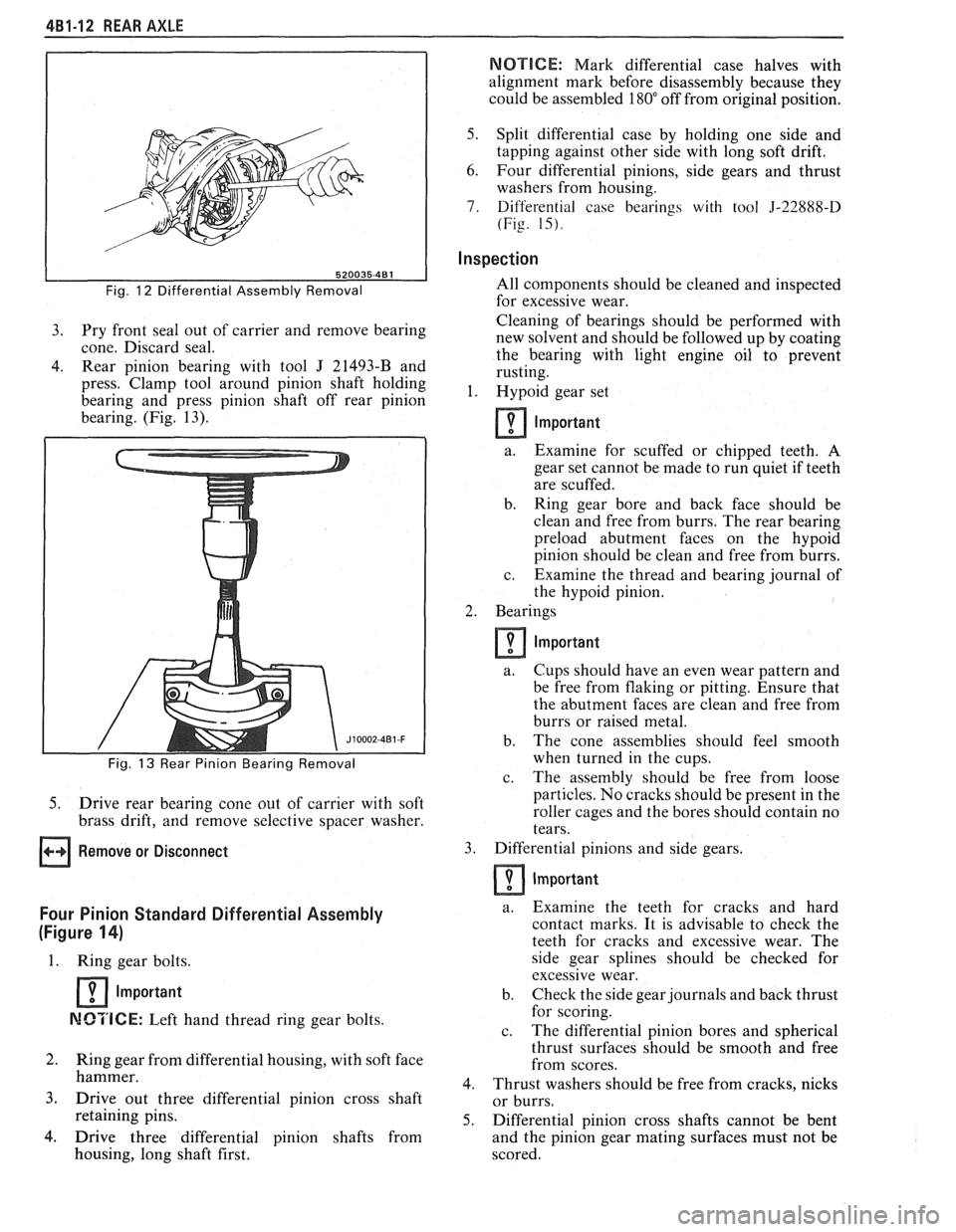
Fig. 12 Differential Assembly Removal
3. Pry front seal out of carrier and remove bearing
cone. Discard seal.
4. Rear pinion bearing with tool J 21493-B and
press. Clamp tool around pinion shaft holding
bearing and press pinion shaft off rear pinion
bearing. (Fig. 13).
I
5. Drive rear bearing cone out of carrier with soft
brass drift, and remove selective spacer washer.
Remove or Disconnect
Four Pinion Standard Differential Assembly
(Figure
14)
1. Ring gear bolts.
1 Important
MCTICE: Left hand thread ring gear bolts.
2. Ring gear from differential housing, with soft face
hammer.
3. Drive out three differential pinion cross shaft
retaining pins.
4. Drive three differential pinion shafts from
housing, long shaft first.
5. Split differential case by holding one side and
tapping against other side with long soft drift.
6. Four differential pinions, side gears and thrust
washers from housing.
7. Differential case bearings with tool 5-22888-D
(Fig. 15).
Inspection
All components should be cleaned and inspected
for excessive wear.
Cleaning of bearings should be performed with
new solvent and should be followed up by coating
the bearing with light engine oil
to prevent
rusting.
1. I-Iypoid gear set
Important
a.
Examine for scuffed or chipped teeth. A
gear set cannot be made to run quiet if teeth
are scuffed.
b. Ring gear bore and back face should be
clean and free from burrs. The rear bearing
preload abutment faces on the
hypoid
pinion should be clean and free from burrs.
c. Examine the thread and bearing journal of
the
hypoid pinion.
2. Bearings
Important
a. Cups should have an even wear pattern and
be free from flaking or pitting. Ensure that
the abutment faces are clean and free from
burrs or raised metal.
b. The cone assemblies should feel smooth
when turned in the cups.
c. The assembly should be free from loose
particles. No cracks should be present in the
roller cages and the bores should contain no
tears.
3. Differential pinions and side gears.
Important
a. Examine the teeth for cracks and hard
contact marks. It is advisable to check the
teeth for cracks and excessive wear. The
side gear splines should be checked for
excessive wear.
b. Check the side gear journals and back thrust
for scoring.
c. The
differential pinion bores and spherical
thrust surfaces should be smooth and free
from scores.
4. Thrust washers should be free from cracks, nicks
or burrs.
5. Differential pinion cross shafts cannot be bent
and the pinion gear mating surfaces must not be
scored.
Page 274 of 1825
REAR AXLE 4B-1
SECTION 4B
REAR AXLE
NOTICE: All rear axle attaching fasteners are an necessary.
Do not use a replacement part of lesser
important part in that they could affect the quality
or substitute design. Torque values must
performance of vital parts and systems, and/or be
used as specified during reassembly to assure
could result in major repair expense. They must proper retention
of all parts. (There is to be no
be replaced with one of the same part number or welding
as it may result in extensive damage and
with an equivalent part if replacement becomes weakening
of the metal.)
CONTENTS
General Description .................................. 4B-1
Standard Rear Axle ................... .. ............ 4B- 1
Diagnosis and Testing ............................... 4B-1
Axle Noises ......................... .. ................ 4B-3
Gear Noise ...................... .. .................. 4B-3
Bearing Noise ........................................ 4B-3
Rear Wheel Bearing Noise ....................... 4B-3
Knock at Low Speeds ............................. 4B-3
Backlash Clunk ...................................... 4B-3
Rear Axle Standard and Limited Slip .......... 4B-3
Pre-Repair Investigation and Trouble
Diagnosis
................................................. 4B-4
Gear Tooth Nomenclature ....................... 4B-4
Tooth Contact Pattern Test ..................... 4B-4
Effects of Increasing Load on
Teeth Contact Pattern
.......................... 4B-4
Adjustments Affecting Tooth
Contact
.................................................. 4B-6
Effects of Pinion Position on Tooth
Pattern
................... ... .................... 4B-6
General information ....................... .. ..... 4B-8
Limited-Slip Rear Axle ............................... 4B-8
On-Vehicle Service ............................. .. ....... 4B-8
Carrier Cover and Gasket .......................... 4B-8
............................................. Axle Shaft 4B-8
Oil Seal and/or Bearing (With
Axle Shaft Removed)
............................. 4B-9
........................................ Pinion Oil Seal 4B-9
........................................... Pinion Flange 4B- 10
..................................... Rear Wheel Bolt 4B- 1 1
.................................................... Unit Repair 4B-1 1
..................................... Rear Axle Assembly 4B- 1 1
Disassembly of Rear Axle
............................................... Assembly 4B- 1 1
.. ..................................... Case Assembly ... 4B- 12
Drive Pinion, Bearing and Races ............. 4B- 12
............................... Bearing Replacement 4B- 12
...................... Setting Drive Pinion Depth 4B- 13
........................................ Rear Axle Case 4B- 14
Side Bearing Preload Adjustment ............ 4B- 15
.................................................. Drive Pinion 4B- 16
Rear Axle Backlash Adjustment .............. 4B- 17
........... Limited Slip Rear Axle (Cone Type) 4B-17
...................................... Auburn Cone Type 4B- 18
.............................................. Specifications 4B- 19
.............................................. Special Tools 4B-20
GENERAL DESCRIPTION
STANDARD REAR AXLE Operation
The rear axle assembly is of the semi-floating type
in which the car weight is carried on the axle housing.
The rear axle assembly is designed for use with an open
drive line and coil springs. The rear axle has a
hypoid
type ring gear and pinion with the centerline of the
pinion gear below the centerline of the ring gear.
All parts necessary to transmit power from the
propeller shaft to the rear wheels are enclosed in a When
the vehicle turns a corner, the outer rear
wheel must turn faster than the inner wheel. The inner
wheel, turning slower than the outer wheel, slows its
differential side gear (as the axle shaft is splined to the
side gear) and the differential pinion gears will roll
around the slowed differential side gear, driving the
other differential side gear and wheel faster.
DIAGNOSIS AND "TESTING
salisbury type axle housing (a carrier casting with tubes Many
noises reported as coming from the rear
pressed and welded into the carrier to form a complete axle assembly actually
originate from other sources
carrier and tube assembly). A removable steel cover such as
tires, road surfaces, wheel bearings, engine,
bolted to the rear of the carrier permits service of the transmission,
muffler or body drumming. A thorough
rear axle without removing the entire assembly from and
careful check should be made to determine the
the car. source
of the noise before disassembling the rear axle.
Page 277 of 1825
4B-4 REAR AXLE
d. Incorrect driveline angle.
Noise changes on a different type of road.
a. Road noise.
b. Tire noise.
Noise tone lowers as car speed is lowered.
a. Tire noise.
Similar noise is produced with car standing and
driving.
a. Engine noise.
b. Transmission noise.
Vibration. a. Rough rear wheel bearing.
b. Unbalanced
or damaged propeller shaft.
c. Tire unbalance.
d. Worn
universal joint in propeller shaft.
e. Incorrect driveline angle.
f. Mis-indexed propeller shaft at pinion
flange.
g. Pinion
flange
runout too great.
A knock or click approximately every two
revolutions of the rear wheel.
a. A rear wheel bearing.
Noise most pronounced on turns.
a. Rear
axle side gear and pinion noise.
A continuous low pitch whirring or scraping
noise starting at relatively low speed.
a. Pinion bearing noise.
Drive noise, coast noise or float noise.
a. Ring and
pinion gear noise.
Clunk on acceleration or deceleration.
a. Worn rear
axle pinion shaft in case or side
gear hub counterbore in case worn oversize.
b. Insufficient
lubrication on propeller shaft
slip yoke.
c. Worn U-joints on
propeller shaft. Front or
rear.
Groan in "Forward" or "Reverse".
a. Wrong
or contaminated lube in rear axle.
b. Worn bushings.
Chatter on turns.
a. Wrong
or contaminated lube in rear axle.
b. Clutch
cone worn and/or
spring(s) worn.
Clunk or knock on rough road operation.
a. Excessive end play of axle shafts to
differential cross shaft.
b. Worn bushings.
PRE-REPAIR INVESTIGATION AND TROUBLE
DIAGNOSIS
A careful1 diagnosis of the rear axle prior to
disassembly will often reveal valuable information as to
the extent and type of repairs or adjustments necessary.
Since frequent causes of axle noises are improper
backlash, pinion bearing pre-load, or side bearing
pre-load, or a combination, a few simple adjustments
may be all that are necessary to correct a problem.
Therefore, before removing the rear axle from the
housing, the following checks should be made with the
results recorded and analyzed:
1) Backlash; 2) Total Assembly
Preload; 3) Tooth Contact Pattern Test;
4)
Fluid Level; and 5) Fluid Contamination.
Use care at all times to keep dirt and other foreign
matter, such as grinder dust, soot or sand, away from
differential to prevent possibility of subsequent failure.
The pinion and ring gear must be completely
assembled, installed and all pre-load and backlash
adjustments completed prior to the start of this method
of pinion depth setting. The following procedure can
be used in place of the gage method of pinion depth
setting.
Gear Tooth Nomenclature
The side of the ring gear tooth which curves
outward, or is convex, is referred to as the "drive" side.
The concave side is the "coast" side. The end of the
tooth nearest center of ring gear is referred to as the
"toe" end. The end of the tooth farthest away from the
center is the "heel" end. Toe end of tooth is smaller
than heel end.
It is very important that tooth contact be tested
before the rear axle carrier assembly is disassembled.
Variations in the carrier or pinion rear bearing may
cause the pinion to be too far away from, or close to,
the ring gear. Thus, the tooth contact must be tested
and corrected, if necessary, or the gears may be noisy.
Tooth Contact Pattern Test
1. Wipe oil out of carrier and carefully clean each
tooth of ring gear.
2. Use gear marking compound part number
1052351 or equivalent and apply this mixture
sparingly to all ring gear teeth, using a medium
stiff brush. When properly used, the area of
pinion tooth contact will be visible when hand
load is applied.
3. Tighten bearing cap bolts to 75
N.m (55 lb. ft.).
4. Expand
brake shoes using parking brake cables
until a torque of 54 to
70 N-m (40-50 lb. ft.) is
required to turn the pinion.
A test made without loading the gears will not
give a satisfactory pattern. Turn pinion flange
with wrench so that ring gear rotates one full
revolution, then reverse rotation so that ring gear
rotates one revolution in opposite direction.
5. Observe
pattern on ring gear teeth and compare
with Fig. 3.
Effects of Increasing Load on Teeth Contact
Pattern
When "load" on ring and pinion gear is
increased, such as when car is accelerated forward
from standstill or from normal drive, the tooth contact
will tend to spread out and, under very heavy load, will
extend from near toe to near heel on the drive side. The
entire contact also tends to shift toward heel under
increasingly heavier loads and will become somewhat
broader with respect to tops and bottoms of teeth. The
patterns obtained by this tooth contact pattern test
approximate a light load and, for this reason, they will
extend only about halfway.
Page 296 of 1825
BRAKES 5-3
DIAGNOSIS AND INSPECTION
BRAKE SYSTEM TESTING
(Figures
2 through 4)
Brakes should be tested on dry, clean, reasonably
smooth and level roadway. A true test of brake performance
cannot be made if the roadway is wet, greasy or covered
with loose dirt so that all tires do not grip the road equally.
Testing will also be affected if the roadway is crowned
which would throw the weight of the car toward the wheels
on one side. If the roadway is too rough, the wheels will tend
to bounce. Test brakes at different car speeds with both light and
heavy pedal pressure, avoid locking the brakes and sliding
the tires. Locked brakes and sliding tires do not indicate
brake efficiency, because heavily braked, but turning
wheels will stop the car in less distance than locked brakes.
More tire-to-road friction is present with a heavily braked
turning tire than with a sliding tire. The brake system is designed and balanced to avoid
locking the wheels, except at very high deceleration levels.
The shortest stopping distance and best control is achieved
without brake lock-up.
Because of high deceleration capability, a firmer pedal
may be felt at higher deceleration levels.
External Conditions That Affect Brake Performance
1. Tires. Tires having unequal contact and grip on road
will cause unequal braking. Tires must be equally
inflated and tread pattern of right and left tires must
be approximately equal.
2. Car Loading. A heavily loaded car requires more
braking effort. When a car has unequal loading, the
most heavily loaded wheels require more braking
power than others.
3. Wheel Alignment. Misalignment of the wheels, par-
ticularly excessive camber and caster, will cause the
brakes to pull to one side.
4. Front Wheel Bearings. A loose front wheel bearing
BRAKE FLUID LEAKS
With engine running at idle and the transmission in neu-
tral, depress the brake pedal and hold a constant foot pres-
sure.
If the pedal gradually falls away with the constant
pressure, the hydraulic system may be leaking. Perform a
visual check to confirm any suspected leak.
Check the master cylinder fluid levels. While a slight drop
in reservoir level does result from normal lining wear, an
abnormally low level in either reservoir indicates
a leak in
the system. The hydraulic system may be leaking either
internally or externally. See "Master Cylinder Check."
Also, the system may appear to pass this test but still have
slight leakage.
If fluid levels are normal, check the vacuum booster
pushrod length. If an incorrect length pushrod is found,
adjust or replace the
pushrod. Check the service brake
pedal travel and the parking brake adjustment.
When checking the fluid levels, the master cylinder reser-
voir may be as low as
25 mm (1 inch) from the top if the front
linings are worn. This is not abnormal.
MASTER CYLINDER CHECK
These checks will help locate some master cylinder mal-
functions. Use the Brake Diagnosis Charts to help isolate
the problem if it is not found by using these tests.
1. Check for a cracked master cylinder casting or brake
fluid around the master cylinder. Leaks are indicated
only if there is at least a drop of fluid. A damp condi-
tion is not abnormal.
2. Check for a binding pedal linkage.
3. Disassemble the master cylinder and check for swol-
len or stretched piston
seal(s). If swollen seals are
found, substandard or contaminated brake fluid
should be suspected.
If contaminated, all compo-
nents should be disassembled and cleaned. All rub-
ber components should be replaced and all the pipes
should be flushed.
permits the front wheel to tilt and lose contact with the
SUBSTANDARD OR CONTAMINATED brake shoe linings causing erratic brake operation. BRAKE FLUID
WARNING LAMP OPERATION
The brake system uses a single red "BRAKE" warning
lamp located in the instrument panel cluster. When the
ignition switch is in the "START" position, the "BRAKE"
warning lamp should come on. It should go off when the
ignition switch returns to the "RUN" position.
The following conditions will activate the "BRAKE"
warning lamp:
1. Parking brake applied. The lamp should be on when
tfie parking brake is applied and the ignition switch is
"ON."
2. Pressure differential switch detects a failure. See
"Brake Pressure Differential Warning Switch" in this
section. Improper
brake fluid, mineral oil or water in the fluid may
cause the brake fluid to boil or the rubber components to
deteriorate.
If piston cups are swollen, the rubber parts have dete-
riorated. This deterioration may also be seen by swollen
wheel cylinder piston cups on the drum brake wheels or a
swollen master cylinder cover diaphragm.
If rubber deterioration is evident, disassemble all hydrau-
lic parts and wash with alcohol. Dry these parts with com-
pressed air before assembly to keep alcohol out of the
system. Replace all rubber parts in the system, including
hoses. Check for fluid on the linings. If excessive fluid is
found, replace the linings.
If master cylinder piston seals are satisfactory, check for
leakage or excessive heat conditions. If condition is not
found, drain fluid, flush with brake fluid, fill and bleed the
system.
Page 300 of 1825
BRAKES 5-7
ONmCAR SERVICE
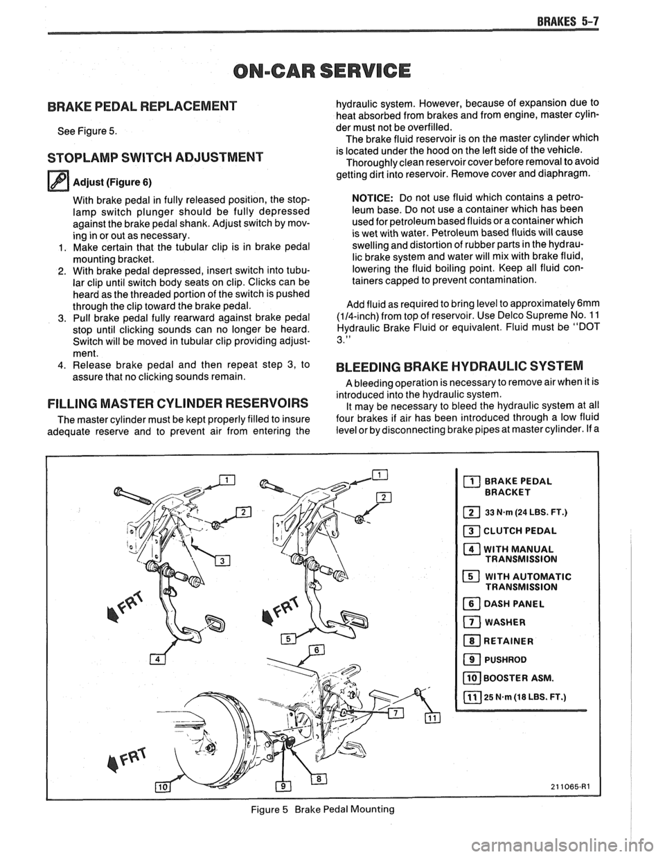
BRAKE PEDAL REPLACEMENT
See Figure 5.
STOPLAMP SWITCH ADJUSTMENT
Adjust (Figure 6)
With brake pedal in fully released position, the stop-
lamp switch plunger should be fully depressed
against the brake pedal shank. Adjust switch by mov-
ing in or out as necessary.
1. Make certain that the tubular clip is in brake pedal
mounting bracket.
2. With brake pedal depressed, insert switch into tubu-
lar clip until switch body seats on clip. Clicks can be
heard as the threaded portion of the switch is pushed
through the clip toward the brake pedal.
3. Pull brake pedal fully rearward against brake pedal
stop until clicking sounds can no longer be heard.
Switch will be moved in tubular clip providing adjust-
ment.
4. Release brake pedal and then repeat step 3, to
assure that no clicking sounds remain.
FILLING MASTER CYLINDER RESERVOIRS
The master cylinder must be kept properly filled to insure
adequate reserve and to prevent air from entering the hydraulic
system. However, because of expansion due to
heat absorbed from brakes and from engine, master cylin-
der must not be overfilled.
The brake fluid reservoir is on the master cylinder which
is located under the hood on the left side of the vehicle.
Thoroughly clean reservoir cover before removal to avoid
getting dirt into reservoir. Remove cover and diaphragm.
NOTICE: Do not use fluid which contains a petro-
leum base. Do not use a container which has been
used for petroleum based fluids or a container which
is wet with water. Petroleum based fluids will cause
swelling and distortion of rubber parts in the hydrau-
lic brake system and water will mix with brake fluid,
lowering the fluid boiling point. Keep all fluid con-
tainers capped to prevent contamination.
Add fluid as required to bring level to
approximately6mm
(114-inch) from top of reservoir. Use Delco Supreme No. 1 1
Hydraulic Brake Fluid or equivalent. Fluid must be "DOT
3."
BLEEDING BRAKE HYDRAULIC SYSTEM
A bleeding operation is necessary to remove air when it is
introduced into the hydraulic system. It may be necessary to bleed the hydraulic system at all
four brakes if air has been introduced through a low fluid
level or by disconnecting brake pipes at master cylinder. If a
Figure
5 Brake Pedal Mounting