Page 105 of 171

SAFETY FIRST!
Step 1: Take note of the location and identification of the
main
components:
Q Step 2: Before starting to remove the unit, unplug all of
the
distributor cap
HT
leads.
M | The TDC and RPM sensor (illustration Job 4-
1, part 4) is correctly positioned during
production and its (adjustable) mounting
plate should not be moved. (In fact, the sensor can be
removed from and refitted to the mounting plate - only the
latter is adjustable.) To prevent the plate from being moved
accidentally, one of the bolts holding the mounting plate to
the engine is of the 'shear' type and has no flats. If there is a
need to adjust the sensor mounting plate, special FIAT tool
1895898000 is required and this then becomes a job for your
FIAT dealer, who will also replace the shear bolt.
• Step 8: FACT FILE: TOP DEAD
CENTRE/RPM SENSOR
PRECAUTIONS -
To be taken when working on a car
with this system:
i) - Never
attempt to start the car with poor battery
connections.
ii) - Do
not use a fast charger to start the engine.
iii) -
Don't disconnect the battery while the engine is
running.
iv) -
Before fast charging
-
disconnect the battery.
vj - Remove
the ECU (electronic control unit) before
putting
the car in a bodyshop paint oven over
80
degrees Celsius.
vi) -
Make sure the ignition is OFF before plugging in
or unplugging
the ECU multi-plug.
vii) -
When electric welding
-
disconnect the battery.
Q Step 5: Turn the engine so that No. 4 piston is at TDC
(compression stroke). See Chapter
5,
Servicing Your Car,
Job 25 Refit the distributor in the reverse order of removal1
with the nuts just loose enough to allow ration of the
distributor body.
• Step 6: E3 INSIDE INFORMATION! At this point a FIAT
agent would fit tool No.1895896000 (1) to the distributor
body and rotate it until the centre of the rotor arm (2) is
aligned with the '0' reference mark on the tool. If such a
tool is not for hire, exactly align the two halves of the
previously scribed mark. This will do the same job
providing the distributor was correctly positioned in the
first place! Tighten the securing nuts. Q
• Step 7: Refit the distributor cap and HT leads.
Job S. Electronic ignition.
FACT FILE: BREAKERLESS INDUCTIVE
DISCHARGE AND DIGIPLEX 2 ALL
ELECTRONIC IGNITION SYSTEMS
Unfortunately, it is not possible to check
either of the two systems described in this
manual without the use of the correct FIAT
diagnostic equipment. If your engine is malfunctioning and
you suspect the ignition, ask your FIAT agent to check it.
109
• Step 3:
Paint a
mark
across
the
distributor
mounting and
spacer lug
to
retain
the exact
positioning when
refitting. Note
the position
of
the rotor,
undo
the three
distributor securing nuts. Remove the vacuum pipe
from the
stub (arrowed). Withdraw the distributor.
• Step 4: If
the
mounting
spacer
is
removed, make
sure
it
is
refitted
with the
recess
(arrowed) facing
downwards.
Page 106 of 171

PART E: ELECTRICAL ARID INSTRUMENTS
PART E: Contents
Job 1. Alternator
-
removal and refitting. Job 10. Rear light cluster
-
replacement.
Job 2. Starter motor
-
removal and refitting. Job 11. Side repeater indicators
-
replacement.
Job 3. Instrument panel
-
removal and refitting. Job 12. Number plate light
-
replacement.
Job 4. Speedometer cable
-
replacement. Job 13. Interior/courtesy light
-
removal and refitting.
Job 5. Windscreen wiper motor
-
replacement. Job 14. Fuel gauge sender unit
-
removal and refitting.
Job 6. Hatchback wiper motor
-
replacement. Job 15. Central locking
-
replacement of components.
Job 7. Windscreen washer pump
-
replacement. Job 16. Electric windows
-
replacement of components.
Job 8. Radio aerial
-
replacement. Job 17. Diesel engines. Glow plugs
-
checking and
Job 9. Headlight cluster
-
replacement. replacement.
Job 1. Alternator - removal
and refitting.
Job 3. Instrument panel -
removal and refitting.
• Step 1: Disconnect the battery earth lead.
Q Step 2: Disconnect all the wires from the back of the
alternator
-
the main output wire is released by undoing its
securing nut. Slacken the bolt securing the inboard end of the
adjustment bar, undo and remove the bolt from the alternator
end of the bar. Slacken the drivebelt and remove it.
Q Step 3: On manual steering cars, unbolt and remove the
adjuster bracket from the cylinder block.
Q Step 4: Release the securing buttons and remove the
engine splash shield on power steering cars.
Q Step 5: Undo the nut from the long through bolt and
note the position of the washers. Support the alternator and
remove the bolt, then withdraw the alternator from the car.
Q Step 6: Refit in reverse order and make sure your
electrical connections are sound. Adjust the drivebelt tension.
See Chapter 5, Servicing Your Car
• Step 1: Disconnect
terminal.
• Step 2: Undo the
screws (arrowed) and
remove the speaker
cover (1).
Job 2. Starter motor - removal
and refitting.
• Step 1: Disconnect the battery earth lead.
• Step 2:
Undo and remove
all the electrical
connections (a)
from the starter
(b) and starter
solenoid (c).
Q Step 4: Refit in reverse order, ensuring that all connec-
tions are sound.
Q Step 5: Raise the instrument panel enough to unplug
the connectors from the rear. Disconnect the speedometer
drive (if non-electronic type) and remove the instrument
panel from the car.
Q Step 6: Refit in the reverse order and be sure that all
connections are properly made.
Job 4. Speedometer cable
replacement.
• Step 1: H INSIDE INFORMATION! The cable comes in
two parts, joined in the middle by a connector (a). Q
• Step 2: Follow Job 3, Steps 1 to 3 Then, lift the
instrument panel
sufficiently so that
you can gain
access to the
cable.
^Jj
Job
4-1
the battery at the negative (earth)
• Step 3: Undo the
exposed screws that
secure the
instrument panel
(arrowed).
• Step 4: Slide
off the screw
cover
(2)
from
the other end of
the instrument
panel and
remove the two
screws found beneath it.
• Step 3:
Undo the three mounting bolts and the wiring harness bracket
from the top bolt and withdraw the starter.
Page 107 of 171

Job 6. Hatchback wiper motor -
replacement.
• Step 3: Disconnect the drive cable from the back of
speedometer.
• Step 4: From under the bonnet, uncouple the two cable
halves
from the centre connector and withdraw the
speedometer section through the bulkhead.
Q Step 5: Disconnect the lower end of the cable from the
gearbox drive and remove it.
G Step 6: Follow the reverse procedure to refit the cable,
being
careful to run the cable as straight as possible, avoiding
sharp bends.
Job 5. Windscreen wiper motor -
replacement.
Q Step 1: Disconnect the battery negative (earth) terminal.
Q Step 2: Note the position of the wiper blades on the
screen. Remove the two windscreen wiper arms and then the
grille
cover.
Q Step 3: Unplug the electrical connector and undo the
four mounting screws (arrowed). Remove the complete
assembly.
Q Step 4: Uncouple the linkage rods from the motor
(arrowed).
Q Step 5: Remove the motor by undoing the three
mounting bolts.
Q Step 6: Note the location of
-
and wiring for
-
these
components.
Q Step 7: Refitting is the reverse of removal, but take care
to position
the wiper arms as you found them after first
making
sure the motor is 'parked'.
IMPORTANT NOTE: For a view of the headlight wiper
motor (where fitted) refer to Job 7. Step 3.
PART A: TIPO MODELS
• Step A1: This
is a view of the
components for
the Tipo rear
wiper.
• Step A2:
Undo the securing
nut and remove
the wiper arm.
• Step A3: Open the tailgate and pull the weather strip
away from the top of the interior trim panel.
• Step A4: Remove the five screws holding the trim in
place
-
three of these also secure the lock.
Q Step A5: Carefully lever out the trim fixing clips freeing
the trim. Unplug the wiring to the tailgate lock motor (if fitted)
and remove the lock/trim panel assembly.
• Step A6: Unplug the wires from the wiper motor, undo
the three screws holding the motor in place and remove the
motor assembly.
• Step A7: Check that the seal in the tailgate wiper shaft
hole is in good condition and then start refitting in reverse
order. Make sure the wiper motor is 'parked' before fitting the
arm and blade.
PART B: TEMPRA MODELS
• Step B1: This shows the layout of the Tempra rear wiper.
Q Step B2: Disconnect the
battery earth lead. Undo the
securing nut and remove the
wiper arm.
Q Step B3: Remove the
motor cover shield.
Q Step B4: Disconnect the
wiring plug and washer
tubing.
• Step B5: From outside,
undo and remove the wiper
shaft nut and retrieve the spacer/seal.
Page 108 of 171

Job
9-2
Job 7. Windscreen washer pump -
replacement.
Job 10. Rear light cluster
replacement.
Job 8. Radio aerial - replacement.
• Step 1: Refer to Job 13 and remove the interior light.
Q Step 2: Now disconnect the aerial lead from the exposed
base and undo the securing nut.
• Step 3: Remove the aerial from outside the car.
Q Step 4: Reverse the process to refit but ensure that the
seal is good between the aerial and the roof to prevent water
ingress.
Job 9. Headlight cluster -
replacement.
• Step 1: Remove the radiator grille
-
see PARTI: BODY
AND INTERIOR
PART A: TIPO MODELS
O Step A1: Disconnect the
battery.
• Step A2: Raise the
tailgate and undo the fixing
screws (arrowed).
• Step A3: Withdraw the
cluster and disconnect the
wiring plug.
• Step 2:
Disconnect the
battery. Unplug all
the wires serving
the light cluster.
Undo the fixing
bolts (arrowed)...
• Step 3: ...and
withdraw the
complete
assembly.
Q Step B6: From inside, undo the mounting bolts and
remove the motor.
Q Step B7: Refit in reverse order.
O Step 1: Disconnect the
battery earth terminal.
• Step 2: Locate the
pump (arrowed), which is a
push fit in the washer fluid
reservoir and disconnect the
electrical plug.
• Step 4: Refit
in the reverse way
and have the
beam alignment
checked by your
local FIAT service
agent.
• Step 3:
Withdraw the
pump and
disconnect the
tubing. This, for
reference, is the
layout of the
headlight washer
pipes and the
headlight wiper
motor.
• Step 4: Check the condition of the seal before refitting in
reverse order.
Page 109 of 171

Job 12. Number plate light -
replacement.
lob 11. Side repeater indicators -
replacement. Job 13. Interior/courtesy light -
removal and refitting.
Job 11-2 |
G Step 1: Remove the
protective cover from under the
wing
to gain access to the back
of the
light unit.
G Step 2: Twist and remove
the
light lens.
G Step 3: Release the two
retaining clips on the light unit
body (arrowed). Withdraw the
light unit and unplug the
connector.
G Step 4: Refit in reverse
order.
PART A: TIPO MODELS
G Step A4:
Undo the two
screws to detach
the printed
circuit/bulb holder
(2) from
the
cluster (1).
G Step A5:
Reverse these
operations to refit.
PART B: TEMPRA MODELS
G Step B1: Disconnect the battery earth lead.
G Step B2: Undo the screw at the top and remove the lens.
IMPORTANT
NOTE: Some
types are held in
place with
screws, found
beneath the
G Step B3:
SALOON MODELS.
This is
the layout of
the
components.
See
Step B4.
G Step B4:
ESTATE MODELS.
Unplug the wiring
connector. Undo
the
three screws
(positions arrowed)
and
withdraw the
light
cluster.
G Step B5: Refit
in
reverse order.
Q Step 1: Remove
the battery earth
lead. Use a screw-
driver and carefully
prise off the interior
light lens.
Job 10-B3
Job 10-B4
• Step A1: Undo the six fixing screws (arrowed)...
• Step A3:
Unplug the wires
from the bulb
holders
(1)
and
the unit becomes
free.
PART B: TEMPRA MODELS
• Step B1: Release the number plate light securing clips
and withdraw the lights.
IG Step B2: Disconnect the wiring plug and remove the
lights.
O Step B3: Refit in reverse order.
• Step A2:
...and withdraw
the unit.
Job 10-A4
• Step 2: Release
the press clips, two
on each end
(arrowed) unplug
the connector and
withdraw the light.
Page 110 of 171

Job 15. Central locking -
replacement off components.
Job 14. Fuel gauge sender unit
removal and refitting.
SAFETY FIRST!
• Carry out this work out of doors, away from sources
of ignition.
• Make the open aperture on top of the fuel tank air
tight as quickly as possible.
• You should carry out this job when the fuel is at a
low level.
VEHICLES WITH ELECTRIC FUEL PUMPS
(NOT ENGINE MOUNTED)
Job 16. Electric windows -
replacement of components.
courtesy light lens and/or panel. The connectors are on
the rear of the unit.
• Step 3: The estate car has a rear courtesy light which is
removed as in Step 1 and 2
LJ Step 4: Refit in the reverse order.
PART A: ELECTRONIC CONTROL UNIT
• Step A1: You
will find the
electronic control
unit
(1)
mounted
beside the
junction unit...
PART A: ELECTRONIC CONTROL UNIT
• Step A1: Disconnect the battery at the earth terminal.
• Step A2: The
electronic control unit
(1) is mounted directly
on the junction unit to
the left of the foot
pedals. To change it,
simply unplug it and
plug the new one in.
• Step A3:
Reconnect the battery.
PART B: DOOR LOCK SWITCHES AND MOTORS
• Step B1: Both door lock switches and motors are an
integral part of the lock assembly. Therefore, if a fault
develops in either, the complete unit will have to be changed.
See PARTI: BODYWORK AND INTERIOR
• Step A2: ...while the
circuit fuse (2) is on the
junction unit holder. First,
disconnect the battery
earth lead.
• Step A3: Disconnect
the electrical plugs, undo
the securing screws and
withdraw the unit.
• Step A4: Refit in
reverse order.
Q Step 1: Disconnect the battery earth lead.
Q Step 2: Lift the luggage compartment floor covering and
prise the round plastic cover from the floor to expose the
sender unit.
Q Step 3: Unplug the sender unit wires and position them
out of the way.
• Step 4: Using the
two opposing lugs on
the unit, (FIAT tool no.
1854045000 or similar
would be useful) twist
it in an anti-clockwise
direction and remove
it from the fuel pipe
housing.
C-) Step 6: Refit in the reverse order.
VEHICLES WITH
ENGINE MOUNTED
FUEL PUMPS
• Step 7: Where a
mechanical fuel pump is
fitted, the sender unit
looks like this. A ring nut
is use to secure it to the
top of the fuel tank.
• Step 5: Check
the condition of the
sealing ring and replace it if necessary.
Job 16-A1
Page 111 of 171
 and remove the bridging
strip (b) from bet")
Job 17. Diesel engines - Glow
plugs, checking and replacement.
LI Step 1: Disconnect the battery earth lead. Undo the
retaining nut at each plug top (a) and remove the bridging
strip (b) from between the glow plugs (complete glow plug -
inset).
• Step 2: With the
wire or connecting strap
removed, unscrew each
plug from the cylinder
head by just a couple of
turns using a ring spanner
(as shown) or socket.
H INSIDE INFORMATION: It is false economy to renew
only one glow plug at a time
-
we recommend a
complete set of new plugs if any one plug is in poor
condition. E9
• Step 6: Refit the glow plugs and tighten to their specified
torque
-
see Chapter 3, Facts and Figures. Over tightening a
glow plug can damage it!
• Step 7: Refit the bridging strip and connect the supply
lead.
17-1
PART B: WINDOW CONTROLS
Q Step B1: Disconnect the battery earth terminal.
Q Step B2: Undo the screw and remove the armrest trim,
then undo the screws fixing the armrest and withdraw it
enough to unplug the wiring. See PARTI: BODYWORK AND
INTERIOR.
• Step 3: Clean away
dirt from around the
plugs, then fully unscrew
and remove them. It's a
good idea to blank off
the plug hole with cloth
to prevent dirt from
entering.
• Step 4: Examine the condition of each plug by wiping
soot away and examining for erosion of the element sheath.
• Step 5: Check the internal resistance of each glow plug
by connecting across a resistance meter. You are looking for a
resistance of 5 ohms or less. If the reading is much higher
than this, or is infinity, the plug must be renewed.
Q Step B4: Refit in the reverse order.
PART C: COURTESY LIGHT/WINDOW LIFT INTERLOCK
SWITCHES
Q Step C3: Refit in reverse order.
PART D: WINDOW OPERATING MOTOR
Q Step D1: The motors are an integral part of the winding
mechanism and therefore can only be changed as a complete
assembly. Refer to PART I: BODYWORK AND INTERIOR
Q Step B3: From inside the armrest, undo the retaining
screws and
detach the control panel from the armrest.
G Step C1: Disconnect the battery earth lead.
Q Step C2: Take off the rubber dust cover (3), prise the
switch out of the panel and disconnect the wire.
Page 112 of 171

-
Job 2. Carburettor
-
removal and refitting. replacement.
Job 3.")
PART F: FUEL AMD EXHAUST SYSTEMS
PART F: Contents
Job 1. Fuel system types. Job 9. Electric fuel pump, petrol engine (S.P.I.)
-
Job 2. Carburettor
-
removal and refitting. replacement.
Job 3. Petrol injection unit
-
removal and refitting. Job 10. Fuel tank
-
removal and refitting.
Job 4. Accelerator cable, carburettor engines
-
replacement Job 11. Hot air hoses/thermo-valves
-
general.
and adjustment. Job 12. Lambda sensor (S.P.I, engines)
-
replacement.
Job 5. Carburettor choke cable
-
replacement and Job 13. Fuel evaporation system.
adjustment. Job 14. Exhaust system
-
replacement.
Job 6. Accelerator cable, petrol injection engines -Job 15. Turbocharger, diesel engine
-
replacement.
replacement and adjustment. Job 16. Diesel injection pump
-
removal and refitting.
Job 7. Diesel engines. Accelerator cable
-
replacement and Job 17. Diesel injectors
-
remove and refit.
adjustment. Job 18. Bleeding Diesel fuel system.
Job 8. Mechanical fuel pump, petrol engine (carburettored) -
replacement.
Job 1. Fuel system types.
FACT FILE: FUEL INJECTION/ELECTRONIC
IGNITION PRECAUTIONS
OBSERVE THE FOLLOWING PRECAUTIONS
WHEN WORKING ON PETROL-ENGINED
VEHICLES WITH FUEL INJECTION - ELECTRONIC
IGNITION SYSTEMS:
• never start the engine when the electrical terminals are
poorly connected or loose on the battery poles;
• never use a quick battery charger to start the engine;
• never disconnect the battery from the car circuit with the
engine running;
• when charging the battery quickly, first disconnect the
battery from the vehicle circuit;
• if the vehicle is placed in a bodyshop drying oven after
painting at a temperature of more than 80 degrees Celsius,
first remove the injection/ignition ECU;
• never connect or disconnect the ECU multiple connector
with the ignition key in MARCIA position;
• always disconnect battery negative lead before carrying out
electrical welding on vehicle.
Note that some systems contain one memory that is always
active (stand-by memory) and that stores learnt self-adaptive
values. Because this data is lost when the battery is discon-
nected, this operation should be carried out as infrequently as
possible.
Refer to illustrations in Job 1 for typical layouts.
It's a good idea to familiarise yourself with the type of fuel
system fitted to your car. These are the main types.
• Type 1: This is the 1400/1600cc carburettored engines
fuel system.
SAFETY FIRST!
• The high pressure pipework on a petrol or diesel fuel
injection system can retain its pressure for days even
after the engine has been switched off.
• When you disconnect the pipework, a jet of fuel can
be emitted under very high pressure
-
strong enough to
penetrate the skin or damage the eyes.
• NEVER work on the fuel pipework when the engine is
running (except when bleeding Diesel injectors
-
see Job
18.
• ALWAYS place a rag over a union while it is being
undone until all the pressure has been let out of the
system.
• You must wear strong rubber gloves and goggles
when disconnecting the fuel injection system's high
pressure pipework. Always disconnect VERY slowly,
letting pressure out progressively.
• See Job 8 for details of how to depressurise the
system.
• Disconnect the battery negative earth before working
on the fuel system.
• Work outdoors and away from sources of flame or
ignition.
• ALWAYS wear rubber gloves
-
don't let your skin come
into contact with fuel.
1 - overflow pipe 2 - safety valve/roll over cut-off device 3 - fuel tank 4 - carburettor 5 - fuel supply, pump to carburettor 6 - mechanical fuel pump
7 - fuel filter 8 - fuel supply, tank to pump 9 - excess fuel return, carburettor to tank 10 - breather pipe, between highest and lowest Job
1-1
 1
1 2
2 3
3 4
4 5
5 6
6 7
7 8
8 9
9 10
10 11
11 12
12 13
13 14
14 15
15 16
16 17
17 18
18 19
19 20
20 21
21 22
22 23
23 24
24 25
25 26
26 27
27 28
28 29
29 30
30 31
31 32
32 33
33 34
34 35
35 36
36 37
37 38
38 39
39 40
40 41
41 42
42 43
43 44
44 45
45 46
46 47
47 48
48 49
49 50
50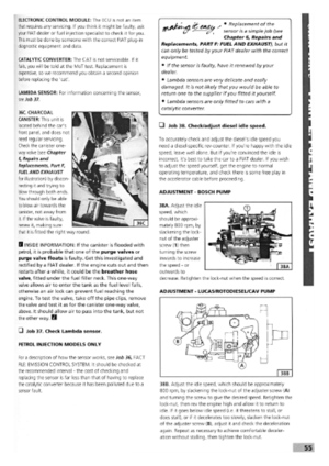 51
51 52
52 53
53 54
54 55
55 56
56 57
57 58
58 59
59 60
60 61
61 62
62 63
63 64
64 65
65 66
66 67
67 68
68 69
69 70
70 71
71 72
72 73
73 74
74 75
75 76
76 77
77 78
78 79
79 80
80 81
81 82
82 83
83 84
84 85
85 86
86 87
87 88
88 89
89 90
90 91
91 92
92 93
93 94
94 95
95 96
96 97
97 98
98 99
99 100
100 101
101 102
102 103
103 104
104 105
105 106
106 107
107 108
108 109
109 110
110 111
111 112
112 113
113 114
114 115
115 116
116 117
117 118
118 119
119 120
120 121
121 122
122 123
123 124
124 125
125 126
126 127
127 128
128 129
129 130
130 131
131 132
132 133
133 134
134 135
135 136
136 137
137 138
138 139
139 140
140 141
141 142
142 143
143 144
144 145
145 146
146 147
147 148
148 149
149 150
150 151
151 152
152 153
153 154
154 155
155 156
156 157
157 158
158 159
159 160
160 161
161 162
162 163
163 164
164 165
165 166
166 167
167 168
168 169
169 170
170