Page 9 of 171

CONTROLS
• 6. LIGHTS AND INDICATORS
DIRECTION INDICATORS AND REAR FOG LIGHT
SWITCH
The lights operate when the key is at the MAR position.
6A. The symbols on
the stalk all
illuminate when the
side or headlights
have been switched
on.
• 3
-
Continuous operation (when the stalk is released
the wiper turns OFF).
WINDSCREEN WASHER/WIPER (REAR)
6C. • Turn switch B
from position 4 to
position 5 to turn on
the rear window
wiper.
• Pull the stalk
toward the steering
wheel to turn on the
rear window washer and wiper (continuous operation).
Both the washer and wiper stop operating when the
stalk is released.
REAR WINDOW DEFROSTER The defroster can only be operated when the key is in
MAR:
LOW BEAM HEADLIGHTS
• Turn the knurled switch from position C to B, for low
beam headlight.
HIGH BEAM HEADLIGHTS
• When the knurled switch pointer is at position B, pull
the stalk towards the steering wheel to switch the
headlights to high beam.
• The panel full headlight beam LED will light up.
• Flick the stalk towards the steering wheel again to
switch off the high beam headlights (the low beam
headlights will remain on).
REAR FOG-GUARD LIGHTS
•
Turn
the knurled switch to B (low beam) and then
press the rear fog switch A at the tip of the stalk to
turn the rear fog-light on.
DIRECTION INDICATORS Move the left-hand column stalk (from its centre
position): • Up = right turn. • Down = left turn.
The panel direction indicator light flashes when the
direction indicators are operating. The stalk returns to
the centre position after completing the turn.
WINDSCREEN WASHER/WIPER CONTROLS
6B: WINDSCREEN WASHER/WIPER (FRONT)
The washer and wiper only operate when the key is
positioned at MAR.
When the windscreen washer
stalk is positioned at:
• 0
-
The windscreen wiper is
off.
•
1 -
Intermittent operation
(adjustable by turning switch C,
from II to III).
• 2
-
Continuous high speed
operation.
Press switch A at the tip of the right-hand stalk to turn
on the rear window defroster. The rear defroster LED
panel indicator will illuminate.
HAZARD WARNING LIGHTS
6D. Press the hazard
light switch (arrowed)
to turn on the hazard
warning lights. All the
directional indicator
lights and the panel
indicator will flash. The
hazard warning lights
work whether the key is inserted or not.
FRONT FOG LIGHTS Press the front fog light switch (key at
MAR, headlights on). The fog light panel
indicator will illuminate.
PANEL LIGHT DIMMER (DIGITAL
INSTRUMENTS)
Press the panel light dimmer switch to
adjust the panel backlighting level (key at
MAR, headlights on).
FUEL CUT-OFF SWITCH
6E. Some models are fitted with a fuel cut-off device,
which cuts the fuel supply off to the engine if the car is
involved in a collision.
• If there are
no signs of fuel
leaks and the
vehicle is in
good enough
condition to
start again,
reactivate the
fuel feed
system by
pressing button A (arrowed), which is located
underneath the passenger's seat.
• Turn the left-hand
column stalk's
knurled switch from
0 to C. The panel
indicator sidelight display will illuminate.
Page 10 of 171

• 9. DOOR MIRROR ADJUSTMENT
• 7. STEERING WHEEL
HEIGHT ADJUSTMENT
7. On some versions the
height of the steering
wheel can be adjusted -
ONLY WITH VEHICLE
STATIONARY!
• Pull lever A, positioned
under the steering wheel, towards you.
• When you have adjusted the wheel to a comfortable
height push the lever back to its original position.
MANUAL TYPE 9A. Move the internal
knob B (attached to the
door mirror A) to adjust
the mirror.
Move it from position 1
to position 2 from
outside the car if extra
clearance is needed.
INDIVIDUAL SETTINGS POWER ADJUSTMENT
9B. When the key is at
MAR, use the 4-way
switch A (near the
handbrake) to adjust the
mirror and switch B to
select left/right mirror.
On some models mirrors are demisted/de-iced
whenever you turn on the rear demister.
• 8. FRONT SEAT ADJUSTMENT
LEGROOM
ADJUSTMENT
8A. Lift lever 1
and exert body
pressure in the
direction desired
to set the seats
fore-and-aft
position:
• Release lever 1, ensuring that the seat is locked in the
desired position.
FRONT SEAT ANGLE ADJUSTMENT
To adjust the angle of the front seats backrest cushion:
• MODELS FITTED WITH A LEVER (ILLUSTRATION 8A, 3):
lift to recline the seat.
• MODELS FITTED WITH AN ADJUSTABLE KNOB (8B, 4):
rotate to recline the seat.
DRIVER'S SEAT HEIGHT ADJUSTMENT
On models with driver's seat height adjustment,
depending on which type you have:
EITHER, pull up lever 2
(illustration &4):
• Move forward to
raise the seat.
• Move backward to
lower the seat.
8C: • OR, pull lever 5
out so that it is at its
full extension.
• Move lever 5 up or
down to adjust the
height of the seat.
After the seat has been adjusted to the required height
slide the extended lever back to its original collapsed
position.
• 10. ELECTRIC WINDOWS
operate the front electric windows (if fitted) when the
key is at MAR:
• A
-
Closes left window.
• B
-
Closes right window.
• C
-
Opens left window.
• D
-
Opens right window.
• E
-
Locks and unlocks the rear electric windows.
• F and G
-
Open and close the rear side windows.
Some models are fitted with two buttons in the front
passenger's armrest to open and close the passenger-
side front window.
• 11. AIR BAG
AIR BAG SAFETY DEVICE
As an extra safety device, some models are fitted with
an air bag, which is stored in the steering wheel. The air
bag inflates immediately to protect the drivers chest and
face in the event of a head on collision.
IMPORTANT NOTE: All diagnosis, repair and
replacement of the air bag device is a specialist job
and is potentially dangerous. It must only be
carried out by your FIAT Service Centre.
I
Page 11 of 171

SAFETY FIRST!
If an air bag has been fitted to your vehicle:
• DO NOT apply stickers or any other objects to
the steering wheel as this may restrict the
operation of the air bag.
• NEVER travel with anything on your lap or in
front of your chest
• NEVER drive with a cigarette, pipe, pen or any
other object in your mouth.
• 12. INTERIOR LIGHTS
COURTESY LIGHT
On most models the courtesy light is positioned in the
centre of the roof.
• With the light switch in the central position the light
turns on when either of the front doors is opened.
• When the switch is in the right position the light
remains on.
• With the switch in the left position the light is
switched off.
• 13. SUNROOF OPERATION
14B. Positioned at the front of the bonnet is a release
catch B. Lift catch up to release.
14C. Lift the
bonnet and pull
the support rod
C out of its
holder.
When the
• 15. LUGGAGE COMPARTMENT
INCREASING THE CARGO AREA
FOLDING THE BACK SEATS
-
Use the following
procedure to fold the rear seat forwards:
• Pull the strap at the centre of the backseat cushion in
an upwards direction to swing up the seat cushion.
15A. On models fitted with lever A, pull the lever up to
release the seat backrest.
15B. Models fitted with a lockable lever B, turn the key
to position 2 to unlock (1 to lock), then lift the lever in
the direction arrowed.
• Fold the backrest cushion forwards.
BONNET AND LUGGAGE
L 2 . fj§
• 14 .BONNET
OPENING THE BONNET
14A. Pull the bonnet release lever A, toward the
steering wheel to release the bonnet catch.
To repositioning the back seats
-
reverse the order
described above.
WHEEL CHANGING
• 16. CHANGING THE WHEEL IN AN
EMERGENCY
CHANGING A WHEEL
Whenever possible park the car on firm level ground.
Put the car into reverse gear and pull on the handbrake.
Keep chocks or pieces of wood in the boot of your car,
which can be wedged in front and behind the
diagonally-opposite wheel to the one being removed to
prevent the car from rolling. If you haven't got a piece
of wood handy, use large rocks or stones.
The location of the spare wheel, jack and tools for most
models is in the luggage compartment under the mat.
However on some models the spare wheel and tools are
located in a storage container within the side walls of the
rear luggage compartment.
bonnet is fully
raised, place the
tip of the rod in
the recess B located in the bonnet.
• Pull handle A down
and turn anti-clockwise,
slides back.
13B. To operate a
sunroof with
electric controls:
13A. SUNROOF CONTROLS
As an optional extra
some models are fitted
with a sunroof. To
operate the manually
operated sunroof:
The sunroof lifts up and then
• Press rocker
switch C either at
the front or back
edge to open or close the sunroof.
Z3
Page 12 of 171

EMERGENCY STARTING
To release the spare
wheel, jack and tool kit:
16A. Undo strap A to
release the jack from the support. Unscrew nut B, to
remove the spare wheel.
16B. Release the jack from the tool stand by lifting tab C.
The arrangement of the tools in their holder might have
one of the configurations shown in illustration 16B.
• 17. RAISING
THE VEHICLE
17A. To raise the vehicle,
position the jack under
the side member, about
20 cm from the wheel
arch. Turn the jack
handle until the its
grooved head (see inset)
fits the flange at the base of the sill.
REMOVING A WHEEL
17B. Loosen all the wheel bolts in the
order shown.
• Lift the car until the wheel is about
25 mm
(1
in.) off the ground.
• The hub cap is secured by only three wheel bolts.
• Remove the hub cap, then unscrew the fourth wheel
bolt, and remove the wheel.
• Put the spare wheel on, making sure that the aligning
peg or pegs on the hub fits into the hole/s in the rim.
• Attach the wheel with a single bolt and then put the
wheel cover back on so that the largest hole fits over
the bolt holding on the wheel. Screw in the other three
bolts, which also hold on the wheel cover.
• Lower the car and remove the jack. Tighten the wheel
bolts evenly in a criss-cross fashion, as shown in
illustration 17C.
RAISING THE VEHICLE WITH A TROLLEY JACK
• 17C. FROM THE FRONT
-
Place a hardwood board
between the jack and the car, see inset. The jack must
ONLY be positioned under the gearbox case support on
the side of the differential gears.
• 17D. FROM THE REAR
-
Put a hardwood board
between the jack and the car ONLY at the back of the
spare wheel housing.
• 18. ENGINE STARTING
JUMP STARTING YOUR CAR
Choose a fully charged battery with the same or higher
capacity than the flat battery in your car, then ...
• Make sure that the car with the flat battery's electrical
equipment has its ignition turned OFF, and that the
ignition keys are removed.
18. • Connect
one of the jump
lead clamps to
the positive
battery post of
your flat
battery. Then
clamp the other
end of the same
lead on to the positive post of the second (charged)
battery.
• Connect one end of the second jump lead to the
negative pole of the charged battery, and attach the
other end to the metal terminal (as shown) of the earth
cable from your car's flat battery.
• Run the engine of the car with the charged battery at
a medium to slow speed.
• Start the engine of the car with the flat battery, and
run the engines of both cars for about three minutes.
• To reduce voltage peaks when disconnecting the
jump leads, turn on the air fan and the heated rear
screen of the car that had the flat battery.
• Remove the jump leads, starting with the negative
clamp connected to the car with the flat battery's earth.
IMPORTANT NOTE: When disconnecting the jump
leads DO NOT switch on the headlights in place of
the heated rear screen, as the peak voltage may
blow the headlight bulbs.
BUMP STARTING YOUR CAR
IMPORTANT NOTES: 1) Never bump start a car
fitted with a catalytic converter, as the sudden rush
of unburnt fuel into the catalytic converter could
damage the converter beyond repair.
2) On models fitted with automatic transmission
bump starting is not possible.
3) Ensure that the key is in the ignition and is
turned to MAR while the car is being pushed, or
the steering wheel will lock.
To bump start a car:
• Place the key in the ignition and turn to MAR.
• Engage a medium gear (2nd or 3rd), NOT REVERSE.
• Hold the clutch pedal down while someone pushes.
• When the pushed car has reached a fair speed, with
the car still in gear, release the clutch pedal.
• The engine should now turn over and start running.
Depress the clutch and keep the car running.
16
Page 13 of 171

CHAPTER 3
FACTS ARID FIGURES
This chapter provides you with
all the information you will
need about your car, especially
in connection with servicing and
repairing it. First, you'll need to
identify the engine type. If you
don't know it already, see
Chapter 6, Repairs and
Replacements.
Before buying parts, be sure to
take your vehicle's chassis and
engine numbers with you
-
see
Auto-Biography on page 1
and PART G: IDENTIFICATION
NUMBERS in this chapter.
Chapter Contents
• -< Page No. Page No.
PART
A:
MAJOR MILESTONES 17 PART E: REPAIR DATA 20
PART
B:
VITAL STATISTICS 18 PART
F:
TORQUE WRENCH SETTINGS 23
PART C: CAPACITIES 19 PART G: IDENTIFICATION NUMBERS 27
PART
D:
SERVICE DATA 19
•
IMPORTANT NOTE: Many detail changes have taken place over the years, and there have been many different Special
Editions and Options available. The following information will be true of most cases but can only be taken as a general
guide. Consult your local FIAT dealer for confirmation.
PART A: MAJOR MILESTONES
Overview Although the Tipo and Tempra were presented as
separate models, they are essentially the same cars, with detail
differences. However, all Tipos are 5-door hatchbacks (apart
from some 3-door 1.4 and the relatively rare 2.0 i.e. 16v, both
from 1993); all Tempras are 4-door saloons (with a boot) or
5-door estates. Apart from the rear bodywork and very slight
differences in rear suspension rates, both models are the
same, although years of production and options available
(including some engine options and some model names) are
not necessarily the same, and changes were not always
introduced to both model names at the same time
-
if at all.
All models come with front disc, rear drum brakes, except the
Tipo
2.0 i.e. 16v (but NOT the 2.0 i.e. GT), and the Tempra 2.0
i.e. SXand SLX models, which have discs front and rear.
IMPORTANT NOTE: This manual does NOT cover 1.8 and
2.0 litre Tipo or Tempra models.
June 1988 Tipo range introduced, as 1.4, 1.4 DGT, 1.6 DGT
and 1.6 DGT SX models with 1372ccand 1580cc petrol
engines. Also 7.97".dswith 1929 turbo diesel engine DGT and
Ids with digital instruments. All models with galvanised steel
body.
October 1988 Tipo 1.7D diesel version launched.
April 1990 Formula and S versions of Tipo 1.4 introduced.
April 1990 Also 1.6 DGT Selecta version introduced with CVT
gearbox.
July 1990 Tempra 1.4 and 1.6 (petrol) and 1.9D, (non-turbo
diesel), and 1.9 TD5 and TD5X (turbo diesel) 4-door saloon
models introduced. CVT auto-transmission available on 1.6
petrol models only
-
same as Selecta on Tipo models, but not
named as such. Tempra 1.8 i.e. SX with high performance
1756cc double-overhead camshaft (DOHC) fuel-injected
engine introduced. Tempra 1.4 and 1.6 basic and 5 models
with regular, analogue instruments; Tempra SXand SX i.e.
with digital instruments.
Tipo 1.8 i.e. DGT model, with high performance 1756cc fuel
injected, DOHC petrol engine introduced.
June 1991 Tempra Station Wagon introduced, as 1.6 or 1.8
i.e. models, with 2-part horizontally split tailgate and high-
roof styling.
Page 14 of 171

October 1991 2.0 i.e. 16v introduced, with 1995cc, 16 valve
high-performance DOHC engine, catalytic converter, sports
suspension, front and rear disc brakes. ABS available as
option.
January 1992 Existing Tipo models lightly facelifted and
redesignated 1.4 Formula, 1.45, 1.6S, 1.6SX, 1.9TD SX,
1.8 i.e. SX. 1.7D discontinued. SX versions with digital
instruments.
Tempra 1.9 TDS (turbo diesel) Station Wagon introduced. 1.4
and 1.9D saloons discontinued.
May 1992 Tempra 1.8 i.e. SX Saloon and Station Wagon
discontinued.
June 1992 Tempra 2.0 i.e. SX saloon and station wagon
models introduced, with high performance 1995cc DOHC fuel
injected engine, catalytic converter and disc brakes front and
rear.
Tipo 1.4 and all Tipo and Tempra 1.6 models (except Selecta)
now with a catalytic converter and fuel injection in place of
Weber twin-choke carburettor. Designated i.e. in badging.
December 1992 Tipo 1.8 i.e. and 1.6 Selecta discontinued.
February 1993 Tipo 2.0 i.e. GT introduced. Slightly lower
performance and spec, version of the 16v model.
July 1993 Tipo 1.4 now available as a 3-door or 5-door
hatchback. 2.0 i.e. 16v now only available as 3-door. Tipo 2.0
i.e. GT replaced by similar spec. 2.0 i.e. SLX.
Tempra 2.0 i.e. SX saloons and estates now only available
with auto, gearbox. Otherwise, SX models become known as
SLX, with colour-coded mirrors and ABS brakes. Most Tempras
now with body-coloured bumpers. 1.9D (non turbo Diesel re-
introduced).
All Tipo and Tempra models now with revised front-end
styling
-
narrower headlights and revised grille. Improved crash
protection, including side impact beams, safety steering wheel
and uprated brakes. Power steering, central locking, electric
windows all standard.
February 1994 Tipo 1.7 non-turbo diesel re-introduced as
1.7 DS.
May 1994 Tempra 1.9DS Station Wagon introduced.
September 1994 Most models available with driver's airbag,
fire prevention system and seat belt pre-tensioners.
December 1994 Tempra 1.6 i.e. versions get M.P.I, engine.
February/March 1995 All models with VIN number window
etching and immobiliser standard on all Tempra petrol models.
October 1995 Immobiliser fitted to Tempra D and TD models.
End of 1995 Tipo discontinued.
Mid-1996 Tempra discontinued.
PART B: VITAL STATISTICS
All Tipo models
-
55 litres, except petrol with catalytic converter
- 51
litres.
All Tempra models
-
65 litres, except petrol with catalytic converter
-
62 litres.
Wheels and Tyres
ENGINE PRESSED STEEL RADIAL TYRE PRESSURES (cold)
WHEEL RIM TYPE TUBELESS FRONT REAR
TYRE TYPE average load heavy load average load heavy load
TIPO MODELS
1.4 and 1.6 Petrol 5.00B x 13H 165/70R13S 2.0 bar/29 psi 2.0 bar/29 psi 1.9 bar/28 psi 2.2 bar/32 psi
1697 Diesel 5.00B x 13H 165/70R 13S 2.1 bar/30 psi 2.1 bar/30 psi 1.9 bar/28 psi 2.2 bar/32 psi
Turbo D 5.5J x 14H
175/65 R
14T 2.2 bar/32 psi 2.4 bar/35 psi 2.2 bar/32 psi 2.4 bar/35 psi
1.4 i.e./1.6 i.e. (1993-on) 5.5J x 14H
165/65 R
14T 2.0 bar/29 psi 2.0 bar/29 psi 1.9 bar/28 psi 2.2 bar/32 psi
1.7D (1993-on) 5.5J x 14H 165/65R 14T 2.1 bar/30 psi 2.1 bar/30 psi 1.9 bar/28 psi 2.2 bar/32 psi
Option
-
certain models 5.5J x 14AH2 185/60R 14H 2.2 bar/32 psi 2.4 bar/35 psi 2.2 bar/32 psi 2.4 bar/35 psi
TEMPRA MODELS
Early 1.4 and 1.6
Saloons 5.00B x 13H 165/70R 13S/T 2.0 bar/29 psi 2.0 bar/29 psi 2.0 bar/29 psi 2.2 bar/32 psi
1.6 SX Saloon 5.5J x 14H 165/65R 14T 2.0 bar/29 psi 2.0 bar/29 psi 2.0 bar/29 psi 2.2 bar/32 psi
1.9D/1.9 TD Saloon
and Late 1.6 i.e. 5.5J x 14H 175/65R 14T/H 2.2 bar/32 psi 2.4 bar/35 psi 2.2 bar/32 psi 2.4 bar/35 psi
1.6/1.9D/1.9TD
Station Wagons 5.5J x 14H 175/65R 14H 2.2 bar/32 psi 2.4 bar/35 psi 2.2 bar/32 psi 3.0 bar/44 psi
Option for Station 5.5J x 14H or AH2 185/60 R 14H 2.2 bar/32 psi 2.4 bar/35 psi 2.2 bar/32 psi 3.0 bar/44 psi
Wagons (alloy)
SPARE WHEEL
-
ALL TIPO AND TEMPRA MODELS (speed limit 50 mph)
Tempra TD Saloon and
ALL Station Wagons 4.00B x 14H 105/70 B14 4.2
bar/61
psi
All other models 4.00Bx14H 135/80 B14 2.8
bar/41
psi
Page 15 of 171
. Ma")
Weights and Dimensions. All weights in kg. All sizes in mm.
All figures are given for 1993 model-year. Other years may vary.
ALL TIPO AND TEMPRA MODELS: Maximum roof load
-
80 kg (all models). Maximum weight on towball, when fitted - 75 kg.
VEHICLE
TIPO MODELS
1.4
1.6 manual
1.6 auto.
1.9 Turbo D
1.7 Diesel
UNLADEN WEIGHT
1030
1050
1080
1160
1060
MAXIMUM
LADEN WEIGHT
1530
1550
1580
1660
1560
TOWABLE LIMITS WITHOUT WITH BRAKES BRAKES
400
400
400
400
400
1100
1100
1100
1200
1100
OVERALL LENGTH
3958
OVERALL WHEEL FRONT WIDTH* BASE TRACK * not including mirrors
1700
All models:
2540 1436
REAR TRACK
1415
HEIGHT (unladen)
1445
TEMPRA MODELS
1.4 Saloon 1075 1575 400 1100
1.6 Saloon 1080 1580 400 1200 Saloons:
1.6 Auto Saloon 1120 1620 400 1100 4354 1695 2540 1425 1415 1445
1.9 D Saloon 1170 1670 400 1200
1.9 TD Saloon 1210 1710 450 1300
1.6 Station Wagon 1140 1705 400 1200
1.6 Auto Station Station Wagons:
Wagon 1180 1750 400 1100 4472 1695 2450 1425 1415 1500*
1.9 D Station (* roof bars - add 40 mm)
Wagon 1230 1800 450 1300
1.9 TD Station
Wagon 1270 1840 450 1300
PART C: CAPACITIES
See RECOMMENDED EL LUBRICANTS on page 154.
PART D: SERVICE DATA
All setting in mm. unless stated otherwise.
Engine
FIRING ORDER: All petrol models 1-3-4-2
INJECTION ORDER: All diesel models 1-3-4-2
IGNITION TIMING in degrees Before Top Dead Centre
-
BTDC:
850 rpm: 1372cc-8to 12 degrees. 1580/1581cc- 10 to 14
degrees.
CO CONTENT AT IDLE (MAX): Petrol only
-
0.5 to 1.5%
Exhaust VALVE CLEARANCES (mm) Inlet
(Checked when engine cold)
Petrol engines
Diesel engines
Other settings
0.4
+/-
0.05
0.3
+/-
0.05
0.5
+/-
0.05
0.35
+/-
0.05
SPARK PLUG TYPES AND GAPS
Model FIAT
1372cc V4LSR
1580/1581
cc V45LSR
Champion Gap (mm)
RN9YC
RN7YC
IDLE SPEED:
Petrol: 800 to 850 rpm
Turbo Diesel: 880 to 920 rpm
Non-turbo Diesel: 740 to 780 rpm
0.7 to 0.8
0.7 to 0.8
CLUTCH ADJUSTMENT: No pedal free-travel. Adjustable pedal
height (see Chapter 5, Job 20).
BRAKE DISC PAD MINIMUM THICKNESS: Front (all models)
and Rear (models with ABS)
-
Brake pad wear warning light on
dash, but also check visually
-
minimum 1.5.
BRAKE SHOE FRICTION LINING MINIMUM THICKNESS: Rear
(when applicable)
-
minimum 1.5.
TYRE PRESSURES: See page 18
Page 16 of 171

BORE:
80.5 86.4 82.6 82.6 82.6
STROKE:
67.4 6")
PART E: REPAIR DATA 1
Engine 'bottom end'
1372 OHC 1580/1581 OHC 1697 Diesel 1929 D 1929 Turbo D
(TdsX model
shown separately,
where different.)
BORE:
80.5 86.4 82.6 82.6 82.6
STROKE:
67.4 67.4 79.2 90 90
REBORE SIZE (steps of 0.01):
80.5-80.55 86.4-86.45 82.6-82.65 82.6-82.65 82.6-82.65
PISTON SIZES:
Size A 80.46-80.47 86.36-86.37 82.53-82.54 82.52.82.53 82.53-82.54
Size C 80.48-80.49 86.38-86.39 82.55-82.56 82.54-82.55 82.55-82.56
Size E 80.5-80.51 86.4-86.41 82.57-82.58 82.56-82.57 82.57-82.58
PISTON PROJECTION AT TDC:
N/A N/A 0.667-1.132 0.367-0.832 -0.032-0.432
PISTON CLEARANCES IN BORE:
0.03-0.05 0.03-0.05 0.06-0.08 0.07-0.09 0.06-0.08
PISTON RING THICKNESS: S^MRttffl
TOP 1.478-1.49 1.478-1.49 2.075-2.095 2.075-2.095 2.575-2.595
SECOND 1.728-1.74 1.728-1.75 1.975-1.99 1.978-1.99 1.978-1.99
BOTTOM 2.975-2.99 2.975-2.99 2.975-2.99 2.975-2.99 2.975-2.99
PISTON RING CLEARANCES -RING-TO-GROOVE:
TOP 0.045-0.077 0.045-0.077 0.08-0.13 0.08-0.13 0.08-0.13
SECOND 0.04-0.072 0.04-0.072 0.03-0.05 0.02-0.052 0.02-0.052
BOTTOM 0.03-0.065 0.03-0.065 0.025-0.05 0.03-0.5 0.03-0.5
PISTON RING END GAP:
1 & 2: 0.3-0.5 1 & 2: 0.3-0.5 1 & 2: 0.3-0.5 1 & 2: 0.3-0.5 1: 0.3-0.5
3: 0.25-0.5 3: 0.25-0.5 3: 0.25-0.5 3: 0.25-0.5 2 & 3: 0.2-0.4
PISTON RING OVERSIZES: (All models) 0.2, 0.4, 0. 6
CRANK MAIN JOURNAL DIAMETER:
1: 50.79-50.8 1: 50.79-50.8 1:52.995-53.004 1: 52.995-53.004 1: 52.995-53.004
2: 50.78-50.79 2: 50.78-50.79 2: 52.986-52.995 2: 52.986-52.995 2: 52.986-52.995
CRANK, BIG-END DIAMETER:
A: 45.513-45.523 A: 45.513-45.523 A: 50.796-50.805 1: 50.796-50.805 A: 50.796-50.805
B: 45.503-45.513 B: 45.503-45.513 B: 50.787-50.796 2: 50.787-50.796 B: 50.787-50.796
MAIN BEARING SHELL THICKNESS:
1: 1.84-1.844 1: 1.84-1.844 1: 1.839-1.843 1: 1.839-1.843 1: 1.837-1.843
2: 1.845-1.849 2: 1.845-1.849 2: 1.843-1.847 2: 1.843-1.847 2: 1.843-1.849
MAIN BEARING CLEARANCES
0.019-0.05 0.019-0.05 0.027-0.062 0.027-0.062 1: 0.027-0.066
2: 0.024-0.963
MAIN BEARING UNDERSIZES:
A: 0.254 A: 0.254 A: 0.254 A: 0.254 A: 0.254
B: 0.508 B: 0.508 B: 0.508 B: 0.508 B: 0.508
BIG-END BEARING SHELL THICKNESS (STANDARC ):
A: 1.535-1.541 A: 1.535-1.541 A: 1.528-1.532 A: 1.528-1.532 A: 1.527-1.533
B: 1.54-1.546 B: 1.54-1.546 B: 1.533-1.537 B: 1.533-1.537 B: 1.533-1.539
BIG-END BEARING CLEARANCE:
0.025-0.063 0.025-0.063 0.028-0.061 0.028-0.061 A: 0.026-0.063
B: 0.023-0.060
BIG-END BEARING UNDERSIZES:
A: 0.254 A: 0.254 A: 0.254 A: 0.254 A: 0.254
B: 0.508 B: 0.508 B: 0.508 B: 0.508 B: 0.508
THRUST WASHER THICKNESS
2.31-2.36 2.31-2.36 2.31-2.36 2.31-2.36 2.31-2.36
THRUST WASHER OVERSIZE:
0.127 0.127 0.127 0.127 0.127
20
 1
1 2
2 3
3 4
4 5
5 6
6 7
7 8
8 9
9 10
10 11
11 12
12 13
13 14
14 15
15 16
16 17
17 18
18 19
19 20
20 21
21 22
22 23
23 24
24 25
25 26
26 27
27 28
28 29
29 30
30 31
31 32
32 33
33 34
34 35
35 36
36 37
37 38
38 39
39 40
40 41
41 42
42 43
43 44
44 45
45 46
46 47
47 48
48 49
49 50
50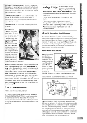 51
51 52
52 53
53 54
54 55
55 56
56 57
57 58
58 59
59 60
60 61
61 62
62 63
63 64
64 65
65 66
66 67
67 68
68 69
69 70
70 71
71 72
72 73
73 74
74 75
75 76
76 77
77 78
78 79
79 80
80 81
81 82
82 83
83 84
84 85
85 86
86 87
87 88
88 89
89 90
90 91
91 92
92 93
93 94
94 95
95 96
96 97
97 98
98 99
99 100
100 101
101 102
102 103
103 104
104 105
105 106
106 107
107 108
108 109
109 110
110 111
111 112
112 113
113 114
114 115
115 116
116 117
117 118
118 119
119 120
120 121
121 122
122 123
123 124
124 125
125 126
126 127
127 128
128 129
129 130
130 131
131 132
132 133
133 134
134 135
135 136
136 137
137 138
138 139
139 140
140 141
141 142
142 143
143 144
144 145
145 146
146 147
147 148
148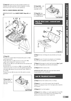 149
149 150
150 151
151 152
152 153
153 154
154 155
155 156
156 157
157 158
158 159
159 160
160 161
161 162
162 163
163 164
164 165
165 166
166 167
167 168
168 169
169 170
170