Page 137 of 171

Job 15. Flexible hoses -
replacement.
• Step 8: Bleed the brakes, see Job
17
H INSIDE INFORMATION: When disconnecting brake
pipes or hoses, it is helpful to minimise brake fluid loss.
This can be done by unscrewing the master cylinder
reservoir cap, laying a sheet of plastic across the
opening, and refitting the cap. This will prevent atmos-
pheric pressure from pushing the fluid out of opened
lines. D
/ • If a rigid pipe starts to
twist with the union, grip
the pipe as lightly as
possible, and see if you can stop it from turning.
• If not, cut through the pipe with a junior hacksaw
and replace the length of rigid pipe.
Job 16. Metal pipes -
replacement.
B INSIDE INFORMATION: When disconnecting brake
pipes or hoses, it is helpful to minimise brake fluid loss.
This can be done by unscrewing the master cylinder
reservoir cap, laying a sheet of plastic across the
opening, and refitting the cap. This will prevent atmos-
pheric pressure from pushing the fluid out of opened
lines. A pipe spanner makes the job much easier! B
Step 1: Undo the unions at each end of a pipe length.
Patience is often required because of the union seizing both in
its threads and on the pipe. See MAKING IT EASY! after Job
15,
Step 8 Use penetrating oil to help free seized unions, and
use a split-ring spanner rather than an open-ended one, to
reduce the risk of rounding off the union nuts.
• Step 2: Detach the pipe length from its securing clips and
remove it.
i^vj ens s * ^ step 3: where possible, use the old pipe as
a pattern to shape the new
one prior to fitting.
• Step 4: Follow the original route and secure the pipe in
the body clips.
Q Step 5: Connect the unions and bleed the system. See
Job
17
Job 17. Brake bleeding.
B INSIDE INFORMATION: Unless the master cylinder or
pressure regulating valve has been disturbed, it will only
be necessary to bleed the end of the braking system
which has been opened. If bleeding the whole system,
start bleeding at the left-hand rear brake. B
G Step 6: These are the correct positions of clips and
protective washers on the hose. Figures with a * are for 1929
turbo Diesel only.
• Step 7: B INSIDE INFORMATION! Changing the rear
hoses is the same, but there are no electrical cables or
protective washers. B
s • When bleeding the rear
brakes, keep the normal
weight on the rear wheels
to prevent the pressure limiting valve from inhibiting
the brake fluid flow.
expert22 f
\9\ http://rutracker.org 141
Ul Step 1: Undo the front hose rigid pipe union (see illus-
tration Job
15-2,
part a) where hose and pipe join at the
support bracket. Use the spanner underneath the bracket to
stop the hose twisting. Take care not to damage the bracket
or tear it off the body.
• Step 2: Pull out the
dip (b).
G Step 3: Unplug the
electrical connection for
the brake pad wear
sensor and unclip it from
the hose.
G Step 4: Unscrew and
remove the hose
from its other end -
it screws into a
female thread.
• Step 5: Refit in
reverse order and
position the
washers and the
position of the
hose at the
anchorage point
(A) as shown, so as
to prevent chafing
on the body when suspension and steering movement take
place. When tightening each union, make sure you haven't
put a twist in the hose!
Page 138 of 171
 onto the
first bleed
screw (b) and
immerse the
other end in a
small quantity
of brake fluid
(c) contained in a glas")
• Step 1:
Push a tight
fitting length
of plastic or
rubber tubing
(a) onto the
first bleed
screw (b) and
immerse the
other end in a
small quantity
of brake fluid
(c) contained in a glass jar in such a way that no air can
accidentally be pulled up the tube.
• Step 2: With a ring spanner (illustrations Job 17-1, part,
d), undo the brake bleed screw (at the drum brake backplate
or on the disc caliper body) by half a turn. Have your helper
push the brake pedal to the floor and hold it there while you
lock up the bleed valve. Then release the pedal slowly. Repeat
several times, with the following suggested dialogue:
YOU. (Open bleed screw) "Open!"
(called
out
loud)
HELPER.
(Pushes
pedal down) "Down!"
YOU.
(Close
bleed screw) "Closed!"
HELPER. (Letspedal up) "Up!"
-
repeated, as necessary.
IMPORTANT NOTE: Take great care not to let the master
cylinder run out of brake fluid. Otherwise you will
introduce fresh air into the system and have to start
again. Use ONLY fresh brake fluid from a previously
unopened container.
• Step 3: Top up the fluid reservoir frequently while
repeating the bleeding operation until all air is expelled from
the brake line (no bubbles appear in the tube or jar).
LI Step 4: Bleed each remaining brake in the same way,
going to the right-hand front next, followed by the right-hand
rear, and finishing with the left-hand front brake. Top up fluid
and check all connections for leaks.
Job 18. Handbrake cables -
replacement.
• Step 1: Familiarise yourself with the handbrake cable
layout. The following instructions refer to this drawing.
FRONT CABLE
Q Step 2: Jack up and support the rear of the car on axle
stands.
LI Step 3: From inside the car, remove the handbrake lever
cover by undoing the single fixing screw and fully release the
handbrake.
D Step 4: Unscrew the adjusting nut from the end of the
cable. You will find it underneath the base of the handbrake
lever.
• Step 5: From under the car, release the front ends of the
rear cables from the equaliser, then pull the front cable
through the floor aperture.
LI Step 6: Refit in the reverse order and adjust the cable nut
until the lever travels no more than three notches on the
ratchet when you pull the brake on, and when released, the
wheels still revolve freely.
REAR CABLES
• Step 7: Carry out Steps 1 to 3.
• Step 8: Unscrew the adjusting nut to the end of its
thread.
• Step 9: Unhook the front of the rear cables from the
equaliser. See Step 5
• Step 10: In the case of rear drum brakes, detach the
cables from the brakes as described in Job 5, Steps 3 and
4.
LI Step 11: In the case of disc rear brakes, see Job 8, Step
1.
• Step 12: Re-assemble in reverse order.
1 - handbrake lever and toothed sector 2 - front cable and anchorage 3 - rear cables 4 - support plate
5 - equaliser 6 - adjusting nut 7 - cable mounting bracket 8 - handbrake lever cover
Job 18-1
• Step 13: Adjust the handbrake
cable until the lever comes up no more
than three notches and when released,
allows both of the rear wheels to revolve
freely. Try spinning them by hand with
rear of the car raised off the ground.
Page 139 of 171

PART I: BODY AMD INTERIOR
PART 1: Contents
Job 1. Bonnet
-
removal and refitting. Job 8. Tempra boot lid locking mechanism
-
removal and
Job 2. Bonnet locking mechanism
-
replacement and refitting.
adjustment. Job 9. Front bumper and grille
-
removal and refitting.
Job 3. Radiator grille
-
removal and refitting. Job 10. Rear bumper
-
removal and refitting.
Job 4. Tipo/Tempra tailgate
-
removal and refitting. Job 11. Door trim panel
-
removal and refitting.
Job 5. Tipo tailgate locking mechanism
-
removal and Job 12. Door component
-
removal and replacement
refitting. Job 13. Door removal, replacement and adjustment.
Job 6. Tempra estate tailgate locking mechanism
-
removal Job 14. Door mirror
-
replacement.
and refitting. Job 15. Sun roof
-
removal and refitting.
Job 7. Tempra boot lid
-
removal and refitting. Job 16. Front seats
-
removal and refitting.
-Job 17. Rear seats
-
removal and refitting.
Job 1. Bonnet - removal and
refitting.
Job 2. Bonnet locking mechanism
- replacement and adjustment.
• Step 1: Note the bonnet hinges, support and stops.
G Step 2: Use the prop and hold the bonnet open. Outline
the hinge positions on the bonnet with masking tape for
accurate refitment.
G Step 3: Ask an assistant to support the bonnet. Undo the
two hinge fixing bolts. Carefully lift the bonnet clear.
if refitting the bonnet, put a
piece of cloth under each
rear corner to protect the bodywork.
• Step 1: This drawing shows left and right hand drive
layouts. Select which is right for your car.
• Step 2: The two screws (illustration Job 2-3 arrowed)
used to fix the locking pin/safety catch assembly to the bonnet
are also used for fore and aft adjustment. This is best done a
little at a time until smooth operation is achieved.
• Step 3: Height
adjustment (levelling with
the wings) is achieved by
screwing the bump stops
(inset, arrowed) up or
down. Then slacken the
G Step 5: When refitting, tighten the bolts just enough to
grip the hinges, then carefully lower the bonnet to check for
correct alignment all round
-
equal gapping.
When the alignment is satisfactory, tighten the bolts to their
correct torque, See Chapter 3, Facts and Figures
[G Step 4: To remove the lock/striker assembly, separate the
cable eyelet from the operating lever hook, see illustration Job
2-1, parts 13 and 14
1 - lock/striker assembly, front panel 2 - locking pin/safety catch, bonnet 3 - release lever. (Also fitted other side, some R/H drive cars) 4 - cable, L/H drive 5 - cable, R/H drive
and secondary cable, R/H drive 7 - screw 8
-
washer 9 - bolt 10 - bolt
11 - cable clip 12 - cable fixing screw 13 - cable eyelet 14 - operating lever hook Job 2-1
locking nut (hidden
behind the locking pin
spring) and screw the
locking pin up or down
until the bonnet will shut
when dropped from 30 cm height and then have no
movement on the lock. Don't forget to tighten the locknut.
Page 140 of 171

Job 3. Radiator grille - removal
and refitting.
Job 5. Tipo tailgate locking
mechanism - removal and
refitting.
Job 4. Tipo/Tempra tailgate -
removal and refitting.
Q Step 5: Undo the securing bolts (see illustration Job
2-1,
part
10)
and remove the lock.
Q Step 6: Refit in reverse order.
Q Step 7: Replace a cable by disconnecting it at each end
and releasing it from any securing clips. Run the new cable
along the same route and re-connect and secure.
• Step 1: Undo the
two fixing screws
(arrowed)...
Q Step 2: ...and pull
out at the top of the grille
to release it from the
securing clips. Withdraw
the grille.
• Step 3: Refit in
reverse order.
• Step 1:
Disconnect the
battery negative
terminal.
• Step 2A: Take
note of this
exploded view of
the Tipo tailgate.
• Step 2B: This is
the Tempra estate
layout.
IMPORTANT
NOTE: While these
instructions are for
the Tipo, the
Tempra estate is
very similar.
• Step 1:
Study this
exploded view of
the locking
mechanism to
help you under-
stand the job.
• Step 2:
Remove the five
bolts (a) securing
the lock
assembly...
• Step 3: ...and
carefully lever off the five
buttons (see illustration
Job
5-2,
arrowed). The
lock assembly (fitted to
the inside of the cover) is
now free.
• Step 6: TIPO ONLY:
Remove the semi-circular
safety spring from the gas
strut balljoints and pull the
socket off the ball.
TEMPRA SW ONLY:
Unbolt the tailgate from the
hinges.
• Step 7: Extract the circlips retaining the hinge pins with
pliers. Support the forward end of the tailgate and knock out
the hinge pins (arrowed), and remove the tailgate.
WARNING! At all costs, avoid loosening the Tipo's hinge
bolts on the body or tailgate
-
or they will have to be
replaced, according to FIAT.
• Step 8: H INSIDE INFORMATION! • When removing
and when refitting, particular attention must be paid
when inserting the stop engagement teeth to avoid
breaking and replacing the stops.
• To refit, insert the upper tooth, then turn the stop
downwards and insert the lower tooth. B
Q Step 9: Continue to re-assemble in reverse order.
Job 5-1
• Step 3:
Disconnect all the
electrical connec-
tions and the washer tubing.
• Step 4: Remove the left cable duct (left-side) and
withdraw the cables from the body shell. Its 'twin', on the
other side, is a plain stop. See Step 8
• Step 4: Unplug the
lock servo control
connector from inside the cover and remove the lock assembly
from the car.
Q Step 5: Disconnect the control rod (see illustration Job
5-1,
part 6) and remove the speed fasteners (Job
5-1,
part
5).
• Step 5: Support the weight of the tailgate with a suitable
length of timber and protective pad.
• Step 6: Remove the two screws (illustration Job
5-1,
parts 4, 9 and
10)
and the closing device (Job
5-1,
part
7).
Page 141 of 171
 from the locking barrel and detach the two retaining
springs. Remove the locking barrel.
Q Step 9: The magnetic locking device (i")
Q Step 7: Remove the sealing ring (illustration Job
5-1,
part 2) from the locking barrel and detach the two retaining
springs. Remove the locking barrel.
Q Step 9: The magnetic locking device (illustration Job
5-1,
part 8) is removed by undoing the two retaining screws.
Q Step 10: Refitting is the reverse of removal.
Job 6. Tempra estate tailgate
locking mechanism - removal
and refitting.
Q Step 1: Remove the trim to expose the mechanism.
G Step 2: The mechanism is a simple lever and rod system
and is dismantled by removing the outer bolt fixings, followed
by the inner lever-end fixings.
Job 7. Tempra boot lid -
removal and refitting.
Q Step 1: These are the boot lid components in exploded
form. Remove the boot interior trim panel and disconnect the
wires serving the door lock motor (a).
G Step 2: Carefully prise out the number plate lights and
disconnect them. Put the cables back inside the double skin.
Q Step 3: Withdraw the cables through the hole by the left
hinge.
L) Step 4: Put some protective rag on the body, under the
sharp corners of the lid. (See illustration Job
7-1,
part b.) Use
masking tape to outline the hinge positions on the lid and
assist in re-alignment.
Q Step 5: Ask an assistant to help support the lid, then
undo the hinge screws, disconnect each hinge assembly (c)
and remove the lid.
Q Step 6: Refit in reverse order.
Job 8. Tempra boot lid locking
mechanism - removal and
refitting.
Q Step 1: Refer to the drawing in Job 7, Step 1.
• Step 2: Remove the interior trim panel for access.
Q Step 3: Unplug the electrical connection from the boot lid
catch. Undo the two securing screws and remove the catch.
Q Step 4: To remove the central locking servo, unplug the
electrical connection, then undo the two mounting screws
and remove the servo.
Q INSIDE INFORMATION! To remove the lock, (which
operates the catch referred to in Step 3) you must first
remove the number plate holder. B
Q Step 5: Remove the number plate lights by easing them
out of their mounting holes and disconnect the electrical plugs.
Gl Step 6: Use a hair dryer and, working from inside the
boot, heat the number plate holder perimeter.
IMPORTANT NOTE: Your hairdryer might not get hot
enough; or it (or a hot air blower) might get too hot and
damage the paintwork. You are recommended to leave
this part of the job to your FIAT dealer, or to proceed
with enormous care.
• Step 7: Release the four clips and push out the number
plate holder/lock assembly.
• Step 8: Undo the three nuts and remove the lock.
Q Step 9: Carefully remove the old sealant from both
surfaces and clean thoroughly with a suitable solvent.
• Step 10: Mount the new lock on the number plate holder
and apply a suitable silicone sealer approximately 8 mm high
in a continuous seam round the perimeter. Level the sealant if
necessary.
• Step 11: Position the number plate holder in the boot lid
hole.
H INSIDE INFORMATION! This is made easier by pressing
out the retaining clips from inside the boot. The
positioning must be completed within 5 minutes of
applying the sealant. Hold the number plate holder in
position with masking tape on the outside and leave to
set for at least 3 hours without any disturbance. D
Q Step 12: Now the remaining parts can be fitted in reverse
order.
Page 142 of 171

Job 9. Front bumper -
removal and refitting.
• Step 1C:
The Tempra
saloon has
slightly
different fixing
positions.
• Step
Open the
Q Step 3: Remove the rear wheel arch liners by undoing the
fixing bolts and buttons.
• Step 4: Undo the bumper fixing bolts (see illustrations
Steps 1A, !B and 1Q and withdraw the bumper from the car.
• Step 5: Refit in the reverse order, but make sure that the
side fixing blocks on the body engage properly with the
guides on the bumper. The bumper slides on/slides off.
Job 11. Door trim panels -
removal and refitting.
IMPORTANT NOTE 1: All of the illustration references in
this job relate to illustration Job 11-A1 and illustration
Job 11-B1.
IMPORTANT NOTE 2: Identify the trim panels fitted to
your car. One piece trim panels (Type A) are the early
type; two piece trim panels (Type B) are the later type.
TYPE A: EARLY TRIM PANELS
Job lO. Rear bumper - removal
and refitting.
H INSIDE INFORMATION! The method of removal is the
same for Tipo and Tempra. Some models with higher
trim levels have decorative bumper inserts. B
• Step 1:
Remove the
grille. See Job
3.
• Step 2:
Remove the
four lower
fixing bolts
(a
x 2
and
b
x
2)...
• Step 3:
...and the
buttons (illustration Job
9-2,
part e) that fix the bumper to
the wheel arch liner.
Q Step 4: Undo the two top fixing bolts (illustration Job
9-
2, parts c) and remove the bumper by sliding/pulling it
forwards.
Q Step 5: Refit in the reverse order, but make sure that the
side fixing blocks (illustrations Job
9-1,
part d) on the body
engages properly with the guides (Job
9-1,
part e) on the
bumper.
• Step 1A:
Q INSIDE
INFOR-
MATION! The
method of
removal and
refitting is the
same for all
variants. The Tempra estate has a three section bumper
which once removed, can be split to replace individual
parts as shown in this drawing. B
• Step 1B:
Some models,
such as this
Tipo, with
higher trim
levels have
decorative
bumper inserts
but otherwise,
removal is the
same.
FRONT DOORS
• Step A1: Remove the
interior door handle trim (11) by
removing the outer screw (12).
• Step A2: Undo the inner
fixing screw (see illustration Job
11-A1,
part 8) and withdraw
the handle far enough to....
• Step A3: .... unplug the
window's electrical connector, where fitted.
B INSIDE INFORMATION! If the window or regulator is
being removed, lower the glass before undoing the plug
Where manually operated windows are fitted, remove
the window regulator handle by hooking out the horse
shoe type retaining clip (arrowed) from behind it. B
2:
tailgate or boot lid and remove the upper fixing bolts.
MMBBMHHi 146
Page 143 of 171

and remove the door
pocket (5).
Q Step B2: Carefully lever off the door handle trim (see illus-
tration Job")
Job 12. Door components,
removal and replacement.
Q Step B1: Undo the four screws
(6)
and remove the door
pocket (5).
Q Step B2: Carefully lever off the door handle trim (see illus-
tration Job 11-B1, part 11).
Q Step B3: Undo the three screws (11-B1, part 12
-
positions
arrowed) and withdraw the handle (11-B1, part 10) enough to....
• Step A4:
Carefully prise out the
escutcheon plate and
twist it in the direction
shown by the arrow to
allow it to be
withdrawn over the
opening lever and
removed.
• Step A5:
Unscrew the six
screws (illustration
Job 11-A1, part 6)
and remove the door
pocket (Job 11-A1,
part 4).
• Step A6:
Unscrew and remove
the internal locking
button (arrowed) and
remove the trim panel
by carefully levering out the door retaining studs with a flat
bladed tool (preferably two-pronged) to fit either side of the
shoulder of part 2, part 3 remaining in the door frame. Care is
needed here to locate each retaining stud and avoid damage
when disconnecting part 2 from part 3.
H INSIDE INFORMATION! Avoid pulling the door trim off
with your hands and tearing the trim next to the studs. H
C_) Step A7: Refit in the reverse order of removal, banging
each retaining stud carefully home with the flat of your hand.
REAR DOORS
Q Step A8: Follow the instructions for the front door, but
ignore those for the door pocket and window switch.
TYPE B: LATER TRIM PANELS.
FRONT DOORS
• Step B6: Remove the door trim as described in Step A6
and Step A7, removing the upper trim (Job 11-B1, part 2) in
a similar way.
REAR DOORS
• Step B7: Follow the instructions for the front door, but
ignore those for the door pocket and window switch.
the six bolts and
nuts (arrowed) fixing the subframe to the door.
H INSIDE INFORMATION! There are two types of door
shell. The early type has a subframe behind the trim
panel which can be removed complete with the window
regulator and door lock, or just the regulator. The later
type has a fixed inner panel and the components are
removed individually. B
PART A : EARLY FRONT DOORS
• Step A1:
Lower the window
fully and remove
the door trim
panel. See Job 11,
Type A.
• Step A2: Peel
off the transparent
covering from the
door panel and
keep it in a dust
free place so that it
will re-stick easily
when refitted.
• Step A3:
Disconnect the lock
control rod and the
door opening rod
(both arrowed).
• Step A4:
Undo and remove
• Step B4:
...disconnect the
electric windows
control where fitted
(arrowed).
• Step B5:
Carefully prise out
the escutcheon plate
(see illustration Job
11-A4) and twist it
in the direction
shown by the arrow to allow it to be withdrawn over the
opening lever and removed.
Page 144 of 171
, then
unplug the wires from
the lock and window
motor (when fitted),
withdraw the
subframe downwards
complete with the
window glass")
• Step A5: Undo
the three lock securing
bolts (arrowed), then
unplug the wires from
the lock and window
motor (when fitted),
withdraw the
subframe downwards
complete with the
window glass and lock.
[J Step A6: Remove
the securing clip (1)....
• Step A7: and
release the electric
window pin.
• Step A8: Remove
the window glass.
• Step A9: Undo
the fixings on the
subframe....
• Step A10:... and
remove the electric
motor (when fitted)
and window lifting
gear.
• Step A11: The
external handle is
removed by undoing
the two nuts (arrowed
and spannered).
• Step A12: Re-
assemble the frame
in reverse order and
install as unit.
• Step A13: Mount
the subframe with just
two bolts, screwed in
but not tightened and
<
out the following test.
• Step A14: TEST FOR ELECTRIC WINDOWS: For this an
ammeter is required and should be connected in series with
the window control circuit. The peak consumption should not
exceed 12A (with a mean value of 8A).The window lifting
time should not exceed 6 seconds. If the current is too high
or the time too long, check the window to guide alignment
and adjust the frame until all is within the set limits.
• Step B5: Unplug
all electrical connectors
inside the door and
undo all the six
mounting bolts and
nuts (arrowed)
securing the subframe.
Q Step B6: Remove
the complete assembly
from the door shell.
Q Step B7: Remove
the securing clip....
• Step A15: TEST FOR MANUAL WINDOWS: Align the
glass in the runners so that it moves with a small amount of
resistance over the whole of its travel. The glass should then
stay in any set position. Keep making minor adjustments until
correct.
• Step A16: When you are satisfied that the subframe is
correctly positioned, fit the remaining nuts and bolts and
tighten them all.
Q Step A17: Continue to refit in the reverse order of
removal.
PART B : EARLY REAR DOORS
• Step B1: Lower the window fully and remove the door
trim panel. See Job
11,
Part A.
• Step B2: Peel off the transparent covering from the door
panel and keep it in a dust free place so that it will re-stick
easily when refitted.
• Step B3:
Remove the
external
handle by
disconnecting
the lock safety
rod and
undoing the
fixing bolts
(arrowed).
• Step B4:
Remove the three lock
bolts (arrowed).
• Step B8: and
release the window glass
• Step B9: Remove the window glass.
Q Step B10: Undo the fixings and remove the window
motor and lifting gear.
 1
1 2
2 3
3 4
4 5
5 6
6 7
7 8
8 9
9 10
10 11
11 12
12 13
13 14
14 15
15 16
16 17
17 18
18 19
19 20
20 21
21 22
22 23
23 24
24 25
25 26
26 27
27 28
28 29
29 30
30 31
31 32
32 33
33 34
34 35
35 36
36 37
37 38
38 39
39 40
40 41
41 42
42 43
43 44
44 45
45 46
46 47
47 48
48 49
49 50
50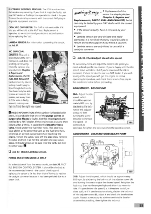 51
51 52
52 53
53 54
54 55
55 56
56 57
57 58
58 59
59 60
60 61
61 62
62 63
63 64
64 65
65 66
66 67
67 68
68 69
69 70
70 71
71 72
72 73
73 74
74 75
75 76
76 77
77 78
78 79
79 80
80 81
81 82
82 83
83 84
84 85
85 86
86 87
87 88
88 89
89 90
90 91
91 92
92 93
93 94
94 95
95 96
96 97
97 98
98 99
99 100
100 101
101 102
102 103
103 104
104 105
105 106
106 107
107 108
108 109
109 110
110 111
111 112
112 113
113 114
114 115
115 116
116 117
117 118
118 119
119 120
120 121
121 122
122 123
123 124
124 125
125 126
126 127
127 128
128 129
129 130
130 131
131 132
132 133
133 134
134 135
135 136
136 137
137 138
138 139
139 140
140 141
141 142
142 143
143 144
144 145
145 146
146 147
147 148
148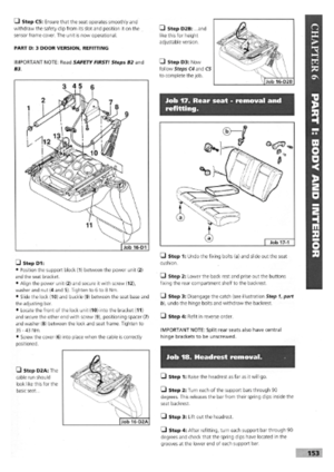 149
149 150
150 151
151 152
152 153
153 154
154 155
155 156
156 157
157 158
158 159
159 160
160 161
161 162
162 163
163 164
164 165
165 166
166 167
167 168
168 169
169 170
170