Page 145 of 171
.
• Step C13:...
Manoeuvre the lock
until you")
-J Step B11: Remove
the lock from the subframe
by levering out the two
plastic retaining studs with
a flat bladed tool
(preferably two-pronged).
• Step C13:...
Manoeuvre the lock
until you are able to
disconnect the central
locking wires and
release them from
their securing points
on the door panel
• Step C14:
Remove the lock
complete with the
remote interior handle
rod and locking rod.
• Step C15: The
exterior door handle
fixing nuts can be
reached inside the
door panel just above
the lock
-
be careful
not to drop them
inside the panel.
• Step C16: Refit in
the reverse order of
removal.
Q Step B12: The window channels can also be unbolted if
required.
Q Step B13: Re-assemble and refit by following Steps A13
to
A18.
PART C: LATER FRONT AND REAR DOORS
IMPORTANT NOTE: We cover removal/replacement of
the electrically operated window mechanism. Removal
of the manually operated regulator mechanism is similar
in principle to the earlier type. See PART A: EARLY
FRONTDOORS
Q Step C1: Remove the door trim panel. See Job 11
Q Step C2: Remove
the transparent
covering from the door
panel and keep it in a
dust free place so that
it will re-stick easily
when refitted.
• Step C3: Undo
the four bolts
• Step C9:.... and withdraw the regulator, motor and guide
assembly from the door.
• Step C10: Refit in the reverse order of removal and
adjust the fit of the glass in the channels for smooth operation
without binding. The glass should then stay in any set
position.
• Step C11: Remove the door trim panel and the trans-
parent covering. See Job 11 and Step B1.
• Step C12: Undo
the three bolts
(arrowed)
Step C5; When
refitting the glass,
move it downwards,
then up and
backwards....
• Step C6:... so that
the guide (arrowed)
engages with the door
window frame.
Q Step C4:....by releasing the clip (see illustration Job 12-
A6). Withdraw the glass.
(arrowed) and lower
the glass to allow the release of the electric window pin...
Job 13. Door removal,
replacement and adjustment.
• Step C7: To
remove the window
regulator/motor, first
unplug the electrical
connection from
position a
• Step C8:.... then
undo the five screws
(see illustration Job
12-C7 arrowed)....
B INSIDE INFORMATION! To avoid the need to 're-hang'
the door, it is best to remove the hinge pins rather than
unbolt the hinge from the body, unless necessary. B
PART A: DOOR REMOVAL.
LI Step A1: Remove the door lining by following the steps
outlined in the relevant part of Job 11.
• Step A2: Disconnect all the electrical cables from the
electrical components inside the door.
Page 146 of 171

B INSIDE INFORMATION! As an alternative to steps A1
and A2 you can disconnect all the electrical plugs under
the dashboard, which have wires which go through to
the door. B
LI Step A3: Support the door using a trolley jack with a
wad of rag on its pad for protection.
LI Step A4: Remove the door restricter pin (inset and
arrowed) with FIAT tool 1878081000 or similar. With a helper
holding the door steady, undo the hinge pin bolts (arrowed),
and lift the door clear.
• Step A5: Refit in reverse order and retighten the hinge
pin bolts.
PART B: DOOR STRIKER ADJUSTMENT.
, ' -u. When checking the door
jpj^ adjustment, keep a window
open to prevent air
pressure from resisting door closure.
• Step B1: Close the door gently at first to check the lock-
to-striker engagement.
• Step B2: Slacken the screws fixing the striker to the door
post just enough to allow you to tap the striker to a new
position.
L) Step B3: Adjust the striker in or out and up or down by
small degrees until correct.
Q Step B4: Fully tighten the striker screws and recheck the
adjustment.
B INSIDE INFORMATION! Shims with a thickness of 1mm
are available from your FIAT dealer to fit under the door
lock striker, if necessary. B
PART C: DOOR HINGE ADJUSTMENT.
IMPORTANT NOTE: Have an assistant support the weight
of the door as the hinge bolts are slackened.
• Step C1: Support the car on axle stands and remove the
road wheel on the side to be worked on.
• Step C2: If
adjusting a front
door, remove the
front wheel arch
liner by undoing the
retaining studs and
screws. Rear doors
are adjusted with
the front door open.
B INSIDE INFORMATION: The bolts fixing the hinges to
the bodywork are very tight. Use a torque wrench or a
proprietary extension on your socket wrench when slack-
ening them. B
Job 14. Door mirror -
replacement.
PART A: MANUAL OPERATION
• Step A1: Pull off
the rubber adjusting
lever cover (a)...
• Step A2: and
unscrew the ring
nut (b).
• Step A3: Lever
off the plastic panel
(c)...
• Step A4: ...undo the two mounting screws (d) and
remove the mirror.
D Step A5: Refit in reverse order.
PART B: ELECTRIC MIRROR
• Step B1: Refer to Job 11 to remove the door trim panel.
• Step B2: Pull back the plastic protective sheet at the
forward edge to expose the mirror wires.
• Step B3: Locate the plugs
-
behind the kick panel by the
inner wheel arch, and disconnect them, pulling them through
to the door.
• Step B4: Lever off the plastic trim, (see Step A3) unplug
the electrical connections and undo the securing screws (see
Step A-4) and withdraw the mirror and wiring.
LI Step B5: Refit in the reverse order of removal.
• Step C3:
Slacken the hinge
screws by just
enough to allow the door to be moved. Adjust the door
position until correct and retighten the screws to 35Nm.
Page 147 of 171

Job 15. Sun roof - removal and
refitting.
PART A: GENERAL
E3 INSIDE INFORMATION! If an electric sunroof fails to
work, it can be operated manually with the aid of a key
positioned behind the cover panel in the roof light
assembly. By engaging the key in the exposed drive pin,
you can turn it and adjust the roof position. Q
• Step A1: SPECIAL NOTE. Here we cover the
replacement of the electric motor (where fitted) and the
glass roof panel. We strongly recommend that any
further work, which could involve the removal of the
headlining, should be entrusted to your FIAT agent or
body specialist.
PART B: TO REMOVE THE MOTOR:
• Step B1: Close the sunroof fully and then disconnect the
battery earth lead.
Q Step B2: Carefully lever out the panel cover and remove
the roof light lens.
Q Step B3: Undo the screws and lower the panel...
G Step B4: ...then unplug the two connectors from the
other side of the panel.
O Step B5: Unplug the connector from the motor cable,
once exposed...
• Step B8: Refit by reassembling in reverse order.
PART C: TO REMOVE THE GLASS PANEL:
• Step C1: Position the glass in the fully tilted mode and
remove the mouldings (arrowed) by sliding them rearwards.
• Step C2: Undo the
mounting bolts (two
per side) found behind
the mouldings...
• Step C3: and
raise the glass to
remove it from the
frame.
• Step C4: Refit in
the reverse order.
Job 16. Front seats - removal and
refitting.
PART A: SEATS WITHOUT PRETENSIONERS
• Step A1:
Undo the screws
(arrowed) and
remove the seat
mounting cover
from both sides.
• Step A2:
Undo the four
bolts
-
two per
side of each seat
-
fixing the runners
to the floor and
remove the seat.
PART B: SEATS WITH SEAT BELT PRETENSIONERS -
REMOVAL
IMPORTANT NOTES: i) In a collision, the pretensioners
are activated whether the belt is buckled or not. They
cannot be reset and must be replaced! If the seat belt
was buckled, it too, must be replaced,
ii) Read Safety First! Steps B2 and B3.
he motor.
SAFETY FIRST!
• Handle pretensioners with extreme care
-
don't drop.
• Never cause impact to the tensioning device
-
which
could set off the pre-loaded spring.
• The components must be fitted with care to avoid
knocking or jarring.
• Detach the pretensioner if working on the seat.
• Always insert the blue safety clip before removing or
refitting the seat
• Never attempt to service or dismantle the unit
• Never grasp the buckle or the power unit
• Step B6:
...then undo the
mounting screws
(arrowed).
D INSIDE
INFORMATION:
The relay is
found here
(a).H
• Step B7: You
can now withdraw
Page 148 of 171

• Step B1: Q INSIDE INFORMATION: The seat belt
buckle has a pop-out tab to show when the pretensioner
has been activated
-
and must be replaced. Job 16-B2,
part a shows the normal, non-activated position. E3
from the buckle side of the seat (5). Unclip the cable (7) from
the bracket and feed it between the base of the seat and the
adjusting bar.
Q Step B8: Undo the power unit retaining screw (see illus-
tration Job
17-C2,
part 3) and remove the unit
(17-C2,
part
2). Recover the rubber support block
(17-C2,
part 1) and save
for re-use. DO NOT attempt to disassemble the unit.
PART C: 5 DOOR VERSION, REFITTING
IMPORTANT NOTE: Read SAFETY FIRST! Steps B2 and
B3.
Q Step C1: Check that the safety clip is properly installed -
do not attempt to force it. DO NOT attempt to disassemble
the unit.
• Step B4:
Remove the backrest
release trim in the
direction indicated
by the lower arrow.
• Step B5:
Remove the seat as
described in PART
A, Steps A1 and
A2.
—I Step B6: Turn the seat over and slide it as far forwards as
it will go on its runners to provide maximum slack on the
bowden cable.
O Step B7: Using a Torx key, available from a motor
accessory store, undo the bolt (see illustration Job
17-C2,
part 6) and release the pretensioner assembly
(17-C2,
part
4)
• Step C2:
• Position the support block (1) between the power unit (2)
and the seat bracket.
• Align the power unit (2) along the seat frame and secure it
with the screw (3) and washer, tightening to 6 to 8 Nm.
• Slide the lock (4) and buckle unit between the seat base and
adjusting bar and locate the lock in bracket (5). Fix the rear
end with the screw (6) and tighten to between 35 and 43 Nm.
• Step C3A: Align
the cable's white paint
spots with the securing
clips on the seat base.
The 5 door's seat cables
should look like this for
the basic seat...
• Step C3B: ...and
the cables should be
located like this for the
height adjustable
version.
• Step C4: Position
the seat centrally on
the runners and refit to
the car, taking care to
handle it as described
in Step B3.
SAFETY FIRST!
• • Step B2: Before
starting to remove the
seat, remove the
safety clip from its
storage position (7)
and fit it into the
mechanism shown
here (6). DO NOT
remove the seat
without the safety clip
in place.
• • Step B3: When
removing or refitting
the seat, grasp the
seat at the arrow points (a) only, never where
indicated by the arrow points (b).
Also, never grasp the seat by:
• the seat belt buckle assembly
• the pretensioner power unit.
Job 16-B3
• •
Job 16-B2
1 - deceleration sensor 2 - power unit 3 - bowden cable
4 - locking system 5 - seat belt buckle 6 - safety clip
Page 149 of 171

Job 17. Rear seat - removal and
refitting.
Job 16-D1
Q Step C5: Ensure that the seat operates smoothly and
withdraw the safety clip from its slot and position it on the
sensor frame cover. The unit is now operational.
PART D: 3 DOOR VERSION, REFITTING
IMPORTANT NOTE: Read SAFETY FIRST! Steps B2 and
B3.
• Step D2B: .. and
like this for height
adjustable version.
• Step D3: Now
follow Steps C4 and C5
to complete the job.
• Step D1:
• Position the support block (1) between the power unit (2)
and the seat bracket.
• Align the power unit (2) and secure it with screw (12),
washer and nut (4 and 5). Tighten to 6 to 8 Nm.
• Slide the lock (10) and buckle (9) between the seat base and
the adjusting bar.
• Locate the front of the lock unit (10) into the bracket (11)
and secure the other end with screw (9), positioning spacer (7)
and washer
(8)
between the lock and seat frame. Tighten to
35 -43
Nm.
• Screw the cover
(6)
into place when the cable is correctly
positioned.
• Step D2A: The
cable run should
look like this for the
basic seat...
• Step 1: Undo the fixing bolts (a) and slide out the seat
cushion.
Q Step 2: Lower the back rest and prise out the buttons
fixing the rear compartment shelf to the backrest.
• Step 3: Disengage the catch (see illustration Step 1, part
b), undo the hinge bolts and withdraw the backrest.
Q Step 4: Refit in reverse order.
IMPORTANT NOTE: Split rear seats also have central
hinge brackets to be unscrewed.
Job 18. Headrest removal.
• Step 1: Raise the headrest as far as it will go.
• Step 2: Turn each of the support bars through 90
degrees. This releases the bar from their spring clips inside the
seat backrest.
Q Step 3: Lift out the headrest.
Q Step 4: After refitting, turn each support bar through 90
degrees and check that the spring clips have located in the
grooves at the lower end of each support bar.
Page 150 of 171

gjpjgjjl 'READING' YOUR SPARK PLUGS
Champion explain how the condition of spark plug firing ends can act as a guide to the state of tune and general condition of the engine. The examples shown are assumed to be the correct grade for the engine.
NORMAL
Core nose lightly coated with grey-brown deposits. Electrodes not burning unduly
-
gap increasing by about 0.01 mm every 1,000 miles approximately (with the use of unleaded fuel). Spark plugs correct for engine.
OIL FOULING
Deposits can short-circuit firing end, weakening or eliminating spark. Causes: worn valve guides, bores or piston rings, or while new engine is running-in. Replace spark plugs. Cure oiling problem.
SPLIT CORE NOSE
(May first appear as hair-line-crack). Probably caused by: Over-advanced ignition timing. Faulty distributor advance mechanism. Use of low octane fuel. Weak mixture. Manifold air-leaks. Cooling system problems. Incorrect gap-setting technique.
HEAVY DEPOSITS
Possible causes: Fuel or oil additives. Excessive upper cylinder lubricant. Worn valve guides. Unvarying speed (stationary engine). Replace spark plugs.
OVERHEATING
Likely causes are: Over-advanced ignition timing, or faulty distributor advance mechanism. Use of low octane fuel. Weak mixture. Discard spark plugs showing signs of overheating, and cure the cause.
CARBON FOULING
Look for dull black sooty deposits. (Unleaded fuel carbon fouling can appear similar to oil fouling). Deposits can short circuit the firing end, weakening or eliminating the spark. Check for: Over-rich mixture, faulty choke or clogged air filter. Replace spark plugs.
INITIAL PRE-IGNITION
Caused by serious overheating. Causes are those listed for overheating, but may be more severe. Corrective measures are urgently needed before engine damage occurs. Discard plugs in this condition.
FACT FILE: CORRECT INSTALLATION
• Make sure seating areas are perfectly clean.
• Insert plug finger tight to seat. Ensure plug 'spins' freely.
• PLUGS WITH SEATING GASKET: Tighten to relevant torque setting.
• PLUGS WITH TAPER SEATS: Tighten a further l/16th turn ONLY - no further!
• Overtightening can damage cylinder head or make taper seat plugs impossible to remove.
RECOMMENDED FL LUBRICANTS
FOR YOUR FIAT TIPO ARID TEMPRA
COMPONENT/ TIPO & TEMPRA TIPO SELECTA & TEMPRA SELECTA TIPO & TEMPRA DIESEL CAPACITY 1.4 and 1.6 1.6 and 1.6 i.e. 1.7 D, 1.9 Dand 1.9 TD
ENGINE SELENIA 20K SELENIA 20K SELENIA TURBO DIESEL CAPACITY 3.8 L 3.8 L/4.2 L 5.0 L
MANUAL TRANSMISSION TUTELA ZC80/S -TUTELA ZC80/S CAPACITY 2.0 L -2.0 L
AUTOMATIC TRANSMISSION -TUTELA CVT -CAPACITY -3.5 L (a) -
DIFFERENTIAL(S) FROM GEARBOX FROM GEARBOX FROM GEARBOX CAPACITY ---
STEERING BOX TUTELA K854 TUTELA K854 TUTELA K854 CAPACITY 80 g (b) 80 g (b) 80 g (b)
CONSTANT VELOCITY JOINTS TUTELA MRM2 TUTELA MRM2 TUTELA MRM2 CAPACITY 95 g (each) 95 g (each) 95 g (each)
BRAKE FLUID RESERVOIR TUTELA PLUS 3 TUTELA PLUS 3 TUTELA PLUS 3 CAPACITY (NON-ABS) 0.40
L
(c) 0.40 L (c) 0.40
L
(c)
COOLANT PARAFLU 11 PARAFLU 11 PARAFLU 11 CAPACITY 6.5 L(d) 6.5 L(d) 8.8
L
(d)
WINDSCREEN WASHER TANK AREXONS DP1 AREXONS DP1 AREXONS DP1 CAPACITY 5.0 L 5.0 L 5.0 L
NOTES: (a) DRAIN/REFILL CAPACITY (b) IF MODEL FITTED WITH POWER ASSISTED STEERING USE 0.75 L TUTELA Gl/A (c) IF ABS BRAKING IS FITTED USE 0.52 L TUTELA TOP 4 (d) COOLING SYSTEM AT A CONCENTRATION OF 50% COOLANT TO 50% WATER
CHANGE PERIODS: See Chapter 5, Service Intervals
154
Page 151 of 171

IMPORTANT NOTE: Not all of the components listed here are fitted to all models.
CHAPTER 7
WIRING DIAGRAMS
IMPORTANT NOTE: Not all of the components listed here
are fitted to all models.
IMPORTANT NOTES:
3. We have sometimes shown the wiring diagram for a
'highest' spec, model, in the knowledge that 'lower'
spec, models are usually similar with the deletion of
certain components.
1. There are several hundred FIAT wiring diagrams for
the whole TIPO range. This is a representative selection,
covering the majority of applications. However, in the
event that your car's details are not covered here,
consult your nearest FIAT dealer.
2 All of the following are Tipo wiring diagrams. Tempra
saloons and estates are essentially similar.
4. 'EEC Stage 2 Engines' In late 1994, Tipo 1.4 and 2 -
Litre and Tempra 1.6 MPI vehicles were modified to suit
new emission regulations. These changes were NOT only
engine-related. Vehicles covered by this manual are Tipo
1.4 (with engine code no. 836A4.000) and Tempra 1.6
(with engine code 159B9.000). See Page 27 for location
of codes.
KEY:
1 Left front light cluster 2 Reversing light switch 3a Left horn 4 Electric cooling fan 5 Dual contact coolant thermal switch 6 Right longitudinal cable connection 7 Right front earth 8 Right front light cluster 9 Right horn 10 Screen/rear window washer pump 11 Left brake pad wear sensor 11A Right brake pad wear sensor 12 Ignition coil 12A Ignition coil with power module 12B Ignition coil with H.T. points 13 Digiplex electronic ignition control unit 13A Digiplex electronic ignition lead connection 13C Diagnostic socket for Digiplex electronic ignition 14 Left front earth 15 Battery earth 16 Engine coolant temperature sender unit 17 Battery 18 Ignition distributor 19 Sparkplug 20 Spark plug 21 Sparkplug 22 Spark plug 23 TDC sensor 24 Alternator 25 Oil pressure switch 26 Connector block 27 Brake fluid level sensor 28 Left side turn signal 30 Idle cut-out device 31 Starter motor 32 Throttle valve sensor 33 Pulse generator for speedometer signal 34 Windscreen wiper 35 Right side turn signal 36 P.T.C. resistor for heating fuel duct 37 Thermal switch for PTC 38 Vacuum sensor for vacuum gauge 39 Fuse and relay control unit E2 Turn signal and hazard warning light flasher E4 Fog light relay E5 Horn relay E6 Heated back window relay E7 Switch discharge connector E9 Windscreen wiper intermittent function E10 Rear fog light relay E11 Dipped beam relay E12 Main beam relay E13 Side light control relay E14 Central locking electronic control unit E1-E3-E8-E15-available (unused)
40 PTC resistor activation relay 41 20A fuse for inlet duct heater circuit 42 25A fuse for electric window ECU 43 Junction between facia cable and heater cable 44 Earth on left hand side of facia 45 Junction between facia cable and left front door
G Horn button H Windscreen wiper stalk I Back window wash/wipe selector L Heated rear windscreen switch M Rear screen wash/wipe switch N Windscreen wiper speed switch cables 56 Junction: facia cable and r.h. rear door cables Electric window control unit 57 Glove compartment light bulb Provision for left front speaker 58 Facia cable coupling with right front door cables Provision for left rear speaker 59 Facia cable coupling with right front door cables Supplementary earth point 60 Provision for right front speaker Instrument panel 60A Provision for right rear speaker A Direction indicators warning light 61 L.h. button for courtesy light and electric window B Side lights warning light 62 Junction between rear cable and left rear door C Main beam headlights warning light cables D Heated rear windscreen warning light 63 Junction between rear cable and left front door E Rear fog lights warning light cables E1 Fog lights warning light 64 Left front door lock motor and left front door F Hazard warning lights warning light open warning light G Battery recharging warning light 65 Left front electric window motor H Insufficient engine oil pressure warning light 66 Electric front window control buttons I Trip counter 67 Cigar lighter J Left brake lining wear warning light 68 Braking light switch J1 Seat belt undone warning light 69 Passenger compartment courtesy light K Handbrake on and low brake fluid level 69A Passenger compartment courtesy light with door warning light lock remote control receiver L Choke warning light 70 Hand brake warning light switch M ABS failure warning light 71 Passenger compartment ventilation fan switch N Instrument panel light bulbs 71A Passenger compartment ventilation control 0 Fuel level gauge 72 Passenger compartment ventilation fan speed P Coolant temperature gauge regulation resistor P1 Engine oil pressure gauge 73 Passenger compartment ventilation fan P2 Engine oil temperature gauge 74 Heater controls light bulbs Q Clock 75 Right front door lock motor and right front door R Heater plugs warning light open warning light S Speedometer 76 Right front electric window motor S1 Speed warning light 77 Right front electric window control button T Rev counter 78 R.h. button for courtesy lights and window U Trailer turn signal warning light 79 Luggage compartment lighting X Water in fuel filter warning light 80 Left rear earth Y Excessive turbocharging air pressure warning 80A Right rear earth light 81 Rear cable connection Y1 Lambda probe failure warning light 82 Left tail-light cluster Z Excessive automatic transmission fluid 83 Left rear door lock motor temperature warning light 84 Fuel level gauge Z1 Injection system failure warning light 85 Tailgate lock/release motor Ignition switch 86 Left number plate light Available for radio 87 Right number plate light Available for radio 88 Rear window wiper motor Hazard warning lights switch 89 Heated rear windscreen Stalk unit 90 Right tail-light cluster A Rear fog lights switch 91 Right rear door lock motor B Exterior lighting selector 92 Glow plug preheating system ECU c Control lighting bulb 93 Glow plugs D Light flasher button 94 Engine cooling fan first speed additional resistor E Turn signal stalk 95 30A fuse for engine cooling fan F Dipped/main beam headlight selector 96 Switch for automatic advance
155
Page 152 of 171
 161 Junction between engine lead and facia leads for 271 Maximum turbo boost pressure warning")
97 Solenoid for automatic cold-start advance device 160 Potentiometer 270 Front cable connection (K.S.B.) 161 Junction between engine lead and facia leads for 271 Maximum turbo boost pressure warning light 98 Engine cut out solenoid on injection pump SPI system switch 99 Cooling fan second speed activation relay 161A Engine lead connection for IAW injection system 272 Front cable connection 100 Fuel pump facia lead connection 163 Bosch SPI electronic injection control unit 273 Front cable connection 101 Electromagnetic sensor for rpm sensor 163A Bosch SPI ignition/injection ECU 274 Front cable connection 102 Turbocharger air pressure switch 164 Diagnostic socket (S.P.I.) 281 Left-hand brake lining connection cable joint 104 10A fuse for ABS device 165 Electric fuel pump 281A Right-hand brake lining connection cable joint 105 Connection for anti-lock brake circuit (Antiskid) 166 Hot Lambda probe 282 CO regulation potentiometer 106 Left hand brake lining wear sensor lead 167 Step motor 286 Electromagnetic sensor on flywheel connection 171 Air temperature sender unit 287 Seat belt undone indicator switch 107 Cut-off control module 173 Throttle position sensor 288 Headlight washer intermittent function 108 Cable connection for air conditioner 174 Absolute pressure sender unit 292 Earth for anti-lock brake system (A.B.S.) 109 Front cable connection 180 Rem. contr. switch for legally specified system 293 Earth for air conditioner fan 111 Electric window ECU supply lead connection 181 Daylight side light remote control switch 294 Facia lead connection 112 Sensor on left front wheel 182 Daylight side light remote control switch 295 Connection between facia cable and rear cable 113 Sensor on right front wheel 184 Power earth 297 EGR device ECU 114 Sensor on left rear wheel 185 Electronic earth 298 Diagnostic socket for EGR device 115 Sensor on right rear wheel 186 Electric sun-roof ECU 299 EGR device control solenoid 116 Hydraulic control unit (A.B.S.) 187 Electric sun-roof circuit connection 300 EGR coolant temperature recording sensor 117 ABS control relay 188 Electric sun-roof end-stop sensor microswitch 301 Potentiometer on injection pump 118 Anti-lock brakes electronic control unit (A.B.S.) 189 Sun-roof operating motor 302 Sensor connection cable junction 119 Device for heated filter 190 Safety pressure switch 303 Low engine oil level indication sensor 120 Heated filter device relay 199 IAW multiple relay 304 Low coolant level indication sensor 121 20A fuse for heated filter device 200 Earth on hydraulic control unit bracket 305 Low washer fluid level indication sensor 122 Device for detecting presence of water in fuel filter 200A IAW injection/ignition ECU bracket earth 306 Oil temperature indication sensor 123 Left fog light 207 Starter enablement relay 307 Oil pressure indication sensor 124 Right fog light 208 Switch on gearbox indicating reverse or neutral 308 Junction with coolant temperature sender unit 125 Connection between front cable and fog light 209 Switch on gear selector leads cables 210 Automatic transmission speed selection ECU (CTX) 311 Front cable connection 126 Fog light switch 211 Parking not engaged warning light 312 Front cable connection 127 Sun-roof activation switch 214 Automatic transmission lead connection 313 Junction between facia lead and legally-specified 129 Electric door mirror control switch 215 T.D.C. AND RPM SENSOR (I.A.W.) leads 130 Electrically-adjustable and heated right-hand door 216 Injection/ignition ECU I.A.W. 314 Relay for legally-specified system mirror 219 1st injector 316 60A fuse for air conditioning system 130-A Electrically-adjustable and heated left-hand door 220 2nd injector 317 40A fuse for air conditioner system mirror 221 3rd injector 318 Diagnostic socket for IAW injection system 131 Left headlight wiper motor 222 4th injector 319 Automatic transmission device display 132 Right headlight wiper motor 224 15A fuse for injectors (Volkswagen) 133 Headlight washer pump 225 Idle speed control solenoid A Economy warning light 135 Left front seat heat pads 226 Provision for air conditioner B Sporty drive warning light 135A Right front seat heat pads 228 Ignition distributor with timing sensor 320 Right rear earth for automatic transmission 136 Air conditioner cable connection 231 Coupling with injection lead (Volkswagen) 137 Air conditioner cable connection 241 Automatic transmission electronic control unit 327 Junction with injector cable 138 Air conditioning system compressor (Volkswagen) 328 Advance cut out heat switch 139 Three stage pressure switch 242 Automatic trans, lead connection (Volkswagen) 329 Remote control switch for shifting advance curve 141 Air Recirculation/outside air intake control motor 243 Automatic trans, lead connection (Volkswagen) 330 Negative battery lead connection 142 Air conditioning system switch 244 ECU for decoding speed selector lever position 331 Prewired engine lead connection 143 Outside air/recirculation switch 245 Solenoid unit on transmission 332 Right hand rod lead connection 146 Air conditioning system ECU 246 Diagnostic connection for automatic transmission 333 Right front seat heating control switch A 40A fuse for engine cooling fan (Volkswagen) 334 Right front seat heating activated warning light B 30A fuse for interior ventilation fan and air 247A Automatic transmission lead connection 335 20A fuse for headlight washer system recirculation motor (Volkswagen) with I.A.W. injection system 336 Air conditioning system switch cable connection C 15A fuse for compressor 248 Automatic transmission lever lock solenoid 337 Ignition coil (1-4) D Interior ventilation fan and air recirculation 249 Kick-down switch 338 Ignition coil (2-3) motor relay 250 Rpm electromagnetic sensor E Compressor dual contact relay 251 Car speed electromagnetic sensor N.D. Connector block welded with ultrasound (band in F Cooling radiator fan first speed relay 252 Multifunction switch unit wiring harness) H Relay for compressor activation 253 Sporty drive switch I Timer for engine cooling fan 261 Junction between facia cable and right rear door Wiring colours: 147 Fast idle valve cables 148 Additional resistor for DIM-DIP circuit 262 Facia lead connection A Light blue 149 DIM-DIP circuit relay 263 Check-panel display B White 150 7.5A fuse for DIM-DIP circuit A Front side light failure warning light C Orange 151 Fuel pump control relay B Driver side front door open warning light G Yellow 152 SPI ECU and injector supply relay C Driver side rear door open warning light H Grey 152A Injector control contactor D Tail-gate open warning light L Blue 153 NA fuel vapour cut-off solenoid E Passenger side rear door open warning light M Brown 154 NC fuel vapour cut-off solenoid F Passenger side front door open warning light N Black 155 10A fuse for fuel pump G Rear side light failure warning light R Red 155A 25A fuse for fuel pump and injectors H Rear fog light failure warning light S Pink 156 Injector and air temperature sensor 1 Right brake light failure warning light V Green 157 Resistor L Number plate light failure warning light z Violet 158 10A fuse for Lambda probe M Left brake light failure warning light 158 5A fuse for I.A.W. ECU 264 Recharging indicator cable connection Most wires have two colours, shown as, for example, 159 Coolant temperature sender unit 269 Air conditioning cable connection CN, which means Orange and Black.
 1
1 2
2 3
3 4
4 5
5 6
6 7
7 8
8 9
9 10
10 11
11 12
12 13
13 14
14 15
15 16
16 17
17 18
18 19
19 20
20 21
21 22
22 23
23 24
24 25
25 26
26 27
27 28
28 29
29 30
30 31
31 32
32 33
33 34
34 35
35 36
36 37
37 38
38 39
39 40
40 41
41 42
42 43
43 44
44 45
45 46
46 47
47 48
48 49
49 50
50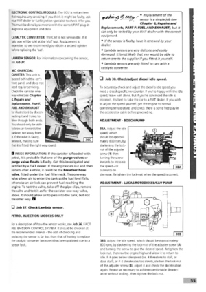 51
51 52
52 53
53 54
54 55
55 56
56 57
57 58
58 59
59 60
60 61
61 62
62 63
63 64
64 65
65 66
66 67
67 68
68 69
69 70
70 71
71 72
72 73
73 74
74 75
75 76
76 77
77 78
78 79
79 80
80 81
81 82
82 83
83 84
84 85
85 86
86 87
87 88
88 89
89 90
90 91
91 92
92 93
93 94
94 95
95 96
96 97
97 98
98 99
99 100
100 101
101 102
102 103
103 104
104 105
105 106
106 107
107 108
108 109
109 110
110 111
111 112
112 113
113 114
114 115
115 116
116 117
117 118
118 119
119 120
120 121
121 122
122 123
123 124
124 125
125 126
126 127
127 128
128 129
129 130
130 131
131 132
132 133
133 134
134 135
135 136
136 137
137 138
138 139
139 140
140 141
141 142
142 143
143 144
144 145
145 146
146 147
147 148
148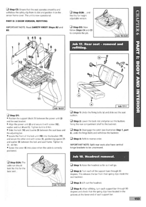 149
149 150
150 151
151 152
152 153
153 154
154 155
155 156
156 157
157 158
158 159
159 160
160 161
161 162
162 163
163 164
164 165
165 166
166 167
167 168
168 169
169 170
170