Page 97 of 171

• Step 13: Tighten the cover bolts evenly to the correct
torque. See Chapter
3,
Facts and Figures.
G Step 14: Smear a little 'copper' grease on the release
bearing guide and the gearbox input shaft.
G Step 15: Refit the transmission. See Job 2.
lob 4. Clutch cable - replacement.
IMPORTANT NOTE: Later cars have hydraulic clutches
see Job 14.
• Step 1: From under the bonnet, slacken the cable
adjusting nut (11). Disconnect the cable from the release lever
and
outer cable bracket.
the car, with securing nuts, or it may be 'worked' in to its
housing) then pull the gaiter/knob assembly from the top of
the lever. (This is a push fit when refitting.)
IG Step 3: From under the car, undo and remove the nut
and bolt securing the control rod (2) from the base of the
gearlever.
• Step 4: Undo the two bolts securing the gearlever
mounting and extract the lever from under the car.
Q Step 5: From under the bonnet, disconnect rods 4, 5 and
6 at the gearbox end by unscrewing them, or by prising the
balls from their sockets, according to type.
Q Step 6: Remove the circlip and washer and lift the
selection link bellcrank (3) off its retaining pin and remove the
complete assembly from the car.
• Step 7: Inspect all components for wear and replace as
necessary, reassembling in the reverse order.
Job 6. Kickdown cable (automatic
transmission) - replacement.
Q Step 1: Drain the automatic transmission oil and remove
the sump. Discard the old gasket. See Chapter
5,
Servicing
Your Car, Job 18
G Step 2: From inside the car, disconnect the cable from
the foot
pedal by removing the securing clip (see illustration
Job 4-1,
part 5) and pulling the cable end off its pivot.
G Step 3: Unbolt the cable retaining plate from the
bulkhead. Pull the cable out from inside the car.
G Step 4: Fit the new cable in the reverse order and adjust.
See Chapter 5,
Servicing Your Car, Job 20
Job 5. Gear lever and linkage -
removal and refitting.
1
-
gear lever mounting 6 - reaction rod 2
•
control rod 3-selection link bellcrank 4
-
gear selection rod 5
-
gear engagement rod
7 - bearings 8 - retaining pin -selection link bellcrank 9 - gearlever knob/gaiter assembly
Job 5-1
^ Step 1: Familiarise yourself with this drawing, which
Step 2
onwards refers. n
J Step 2: Detach the bottom of the gearlever gaiter from
its location
on the tunnel, (it may be held down from beneath
expert22
f:
1 - kick-down cable 2 - idler pulley 3 & 7 - locknuts 4 & 8 - adjusters 5 - accelerator cable 6 - cable-end nipple Job 6-2
• Step 2: Disconnect the cable from the throttle control
idler pulley.
1 - gear selector valve control cable 2 - selector lever 3 - eyelet on selector 4 - cable adjustment nut 5 - bracket fixing selector lever to bodyshell 6 - gearbox lever 7 - bracket for control cable
Q Step 3: Remove the securing clip and disconnect the
kickdown cable (1) from the selector (3).
fl/ifl http://rutracker.org
Page 98 of 171

Job 8. Automatic gear selector
control cable - replacement.
• Step 4:
Release the
outer cable
centring bush
from its
housing in the
gearbox.
• Step 5: H INSIDE INFORMATION! To
do this, you will have to make a simple
tool as shown here. There is no FIAT
'special tool'
-
each dealer has to make
this one himself! Use the tool to push
lightly upwards, so that the cable
centring bush (illustration Job
6-4
arrowed) comes out of its seat. B
• Step 6: Fit the new cable in the reverse
order. Use a new gasket when refitting the
sump.
IMPORTANT NOTE: Readjust the cables if
necessary. See Jobs 7 and 8.
Q Step 7: Refill the transmission with
automatic transmission fluid. See Chapter
3,
Facts and
Figures.
Job 7. Kickdown cable (automatic
transmission) - adjustment.
Refer to the illustrations in Job 6.
Q Step 1: Check that the slow running speed is correct and
the accelerator cable is correctly adjusted, with just a small
amount of slack.
Q Step 2: Disconnect the kickdown cable from the idler
pulley and ensure that it is perfectly free in its operation.
• Step 3: With the selector lever in 'P', start the engine and
let it idle.
Q Step 4: Pull the inner cable by hand until resistance is felt,
caused by the compression of the valves. The cable end should
now line up with its locating slot in the idler pulley
-
if not,
adjust nuts (7) and (8).
[_l Step 5: Reconnect the cable and then switch off the
engine.
• Step 6: Check that when the accelerator pedal is hard
down, there is
1
mm of further movement left on the
kickdown cable, otherwise, make further adjustments on nuts
(7) and (8).
Refer to illustration Job 6, Step 3.
• Step 1: Raise the car and support it securely on axle stands.
• Step 2: Remove the cover from the gear selection
mechanism and familiarise yourself with the drawing referred
to here.
Q Step 3: Manually select the 'P' (park) position, using the
lever beneath the gearchange (see illustration Job
6-3,
part
6).
• Step 4: Disconnect the cable from the selector eyelet (3)
and detach from the slot in the front end of the bracket (5).
Q Step 5: Disconnect the inner cable from the gearlever (6)
and release the outer casing from its gearbox mounted
bracket (7). Remove the cable.
Q Step 6: Ensure that 'P' (park) is still engaged by moving
the gearlever (6
-
beneath the car) fully rearward.
IMPORTANT NOTE: When 'Park' is properly engaged you
will not be able to turn both front wheels in the same
direction at the same time. This is because the trans-
mission should be 'locked' when 'park' is engaged.
• Step 7: Connect the new cable at the bracket (7) and
then at the bottom of the gear lever (6).
• Step 8: Feed the other end of the cable through to the
inside of the car and fix the outer casing into the slot in
bracket (5).
• Step 9: Put the interior selector lever (2) in the 'P' (park)
position and with the inner cable taut, check that the eyelet
(3) aligns perfectly with the selector pin.
• Step 10: If necessary, slacken the adjustment nut (4) and
adjust the position of the eyelet (3) accordingly. Fit the eyelet
to the pin and tighten the nut (4).
• Step 11: Check that the gears engage in their correct
positions on the selector indicator.
T "I FACT FILE: CHECKING AUTOT
qp- TRANSMISSION SELECTION
EL
-
• Now that you have completed the
installation, and BEFORE USING THE
VEHICLE ON THE ROAD, carry out the
following check:
• The engine should only start when you have selected
either 'P' (park), or 'N' (neutral).
• The gear lever selector positions should agree with
those indicated on the display panel.
• When 'R' (reverse) is selected, the reverse light
should come on. With the ignition switched off, the
buzzer should sound if any position other than 'P'
(park) is selected.
Q Step 12: Refit the selection mechanism cover.
0
Job 6-5
Page 99 of 171

Job 9. Drive-shaft - removal
and refitting.
IMPORTANT NOTE: For removal of the diesel Turbo's
drive-shaft, see also PART A: ENGINE, Job 18, Step 16A.
G Step 1: Drain the transmission oil.
• Step 8B: Diesel turbo
models have a bolt-on inboard
flange.
• Step 9: Withdraw the shaft
from the transmission (illus-
tration Job
9-8A,
part b).
G Step 2: Ask a helper to apply the footbrake very firmly
while
you
slacken the drive-shaft-to-hub nut, using a long bar
for
good
leverage after
opening out the
staking on the nut, as
far
as
possible. DON'T
do so
with the car off
the
ground because
the
very large force
needed could pull it off
its stands.
Remove the
nut
after the car has
been raised.
Job 10. Drive-shaft (outer)
constant velocity joint -
G Step 8A: Undo the
inboard
gaiter retaining
clip
(a) and release the
gaiter.
• Step 11: Refill the
transmission with oil.
See Chapter
3,
Facts
and Figures.
G Step 3: Slacken the hub nuts on the side to be worked
on.
Jack up the front of the car and support on axle stands.
Remove the roadwheel.
G Step 6: Remove the
hub
carrier securing
bolts
(arrowed) from the
base
of the front
suspension strut and tap
the
carrier down and out
of the
clamp. Pull the
top
outwards.
G Step 7: Push
or tap
the drive-
shaft
splines
(arrowed) out of
the hub
carrier,
taking
care not to
damage
the
thread.
Q Step 1: Remove the drive-shaft from the car. See Job 9. G Step 4: Unbolt the
brake hose support clip
from
the suspension strut.
G Step 5: Disconnect the
track rod end from the
steering arm using a
suitable splitter tool.
• Step 2: Remove
the gaiter retaining
clip...
Q Step 3: ...and pull
the gaiter clear.
• Step 4: Remove
the circlip and pull the
CV joint from the shaft.
Q Step 5: Thoroughly clean the joint with petrol or other
agent and dry. Check that the balls and their seats are still in a
good, unbroken shiny condition
-
no score marks. Fit a new
joint if in doubt.
• Step 6: Fit the new gaiter onto the shaft, followed by the
CV joint and circlip. Pack the joint with the grease supplied or
with FL Tutela MRM2 grease.
Q Step 7: Pull the gaiter over the joint and secure with the
retaining band or new screw-type clip. The drive-shaft
assembly is now ready for refitting.
• Step 10: Refit in the
reverse order, using a new
drive-shaft nut tightened to the
specified torque. See
Chapter
3,
Facts and
Figures Stake the nut
into the drive shaft
groove, as shown.
Page 100 of 171
 rubber mounting and refit the
weight.
Job 13. Front hub/bearings -
replacement.
Job 11-1
a - distance - 305")
Job 11. Drive-shaft inner spider
joint - replacement.
• Step 3: Replace the (split) rubber mounting and refit the
weight.
Job 13. Front hub/bearings -
replacement.
Job 11-1
a - distance - 305 mm b - spider joint c - inner gaiter d - inner bearing seal e
-
vibration damper f
-
outer gaiter
g - circlip h - outer u.j. i - hub mounting spline
• Step 1: Note the arrangement of the inner spider joint
and drive-shaft components.
Q Step 2: Remove the
drive-shaft from the car. See
Job 9.
• Step 3: Remove the
circlip and pull or press the
spider joint from the drive-
shaft.
• Step 4: Remove the inner gaiter (illustration Job
11-1,
part c) from the seal bearing (Job
11-1,
partd). Check the
bearing for wear and smooth operation.
Q Step 5: Replace it if necessary by using a standard type
puller to remove it from the shaft, driving the new one into
position with a suitable length of tubing.
Q Step 6: After obtaining a new spider joint, if necessary,
(available as a complete replacement item from your FIAT
dealership), fit the new gaiter and its retainer to the shaft,
followed by the spider joint and circlip. No lubrication is
required prior to refitting the drive-shaft.
• Step 7: E9 INSIDE INFORMATION! The turbo diesel
uses an inboard CV joint similar to the outer one except
that it has a flange for attachment to the transmission.
(See PART A: ENGINE, Job 18, Step 16A ) Inspect and
replace in the same way as the outer one. The interme-
diate shaft can only be inspected for wear in its bearing
which cannot be removed separately. Therefore, the
whole unit must be changed if defects are found. Q
Job 12. Drive-shaft damper -
replacement.
Refer to Job
11,
Step 1
Q Step 1: A damper is fitted to the right-hand drive-shaft to
prevent vibration in what is a long drive-shaft. The rubber
mounting can disintegrate or become damaged.
Q Step 2: Use an Allen key to separate the two halves of
the weight.
s * You ™yfind *
" U ' necessary to pull out
gently
on the stub axle and at
the
same time tap lightly (so you don't damage the
thread) on the end of the shaft to knock it through.
• Retrieve the stub axle/hub assembly.
Q Step 7: Use a large vice or a press to push the hub out of
the stub axle.
• Step 8: You may have to remove the bearing inner track
from the hub if it comes out with it.
• Step 2: Partly dismantle the front suspension as described
in Job 9. Steps 2 to 6.
• Step 3: Unbolt the brake caliper and support bracket and
tie it clear.
• Step 1: Take note of the components illustrated here.
Also, see PART G: STEERING AND SUSPENSION, Job
12
where this work is described in more detail.
Q Step 4: Unbolt the brake disc and shield.
• Step 5: Undo the track control arm to stub axle pinch
bolt and
withdraw the
balljoint pin from
the stub axle.
• Step 6: Ease
the stub axle
(illustration Job
13-1,
parts d
and c, combined)
off the drive-
shaft splines (Job
11-1,
parti)
leaving the
inboard end of the
mission.
drive-shaft still attached to the trans-
Page 101 of 171

Job 14. Hydraulic clutch
components.
Later Tipos
and Tempras used a hydraulic clutch in place of
the cable
arrangement used on the early cars. No adjustment
is
possible.
a - clutch fluid reservoir b - master cylinder supply hose c - boot d - master cylinder e - mounting bracket f - cover
a
-
threaded cap b - seals c - master cylinder body
d - slave cylinder body e - bleed screw cap f - bleed screw
Job 14-2
g h i
i k
• Step 1: This is the layout of the hydraulic clutch compo-
nents. Note that the master cylinder supply hose (b) is a low
pressure hose. The method of disconnecting the rigid hose (k)
and the flexible hose (h) is very similar to that for disconnecting
the brake hoses in PART H: BRAKES, Jobs
15
and 16
Removal of the master cylinder or slave cylinder, should
replacement become necessary, can be easily discerned from
the drawing shown here. Note that, if the clevis pin which
holds the master cylinder to the pedal is worn, it should be
replaced. The master cylinder bolts can be reached only after
the cover (f) has been undipped and removed. The slave
cylinder is held to the gearbox casing by the bracket (e) and
must first be disconnected from the clutch arm (I).
• Step 2: These are the internal components of the clutch
master and slave cylinders. Because the clutch components are
not as safely critical as brake components, it is acceptable to
- mounting bracket - vibration damper - rigid hose - clutch operating arm Job 14-1
• Step 9:
Remove the
bearing
retention
cirdip from the
stub axle
(also,
Job 13-1, part
«...
- slave cylinder - flexible hose • Step 10:
...and press out
the old
bearing
{Job
13-1,
part c).
Note
the
inner race
usually breaks
free and
has to
be drifted
off
the hub,
as
shown.
Q Step 11: Clean the stub axle and press in the new
bearing, putting pressure on the outer track only. Refit
the
cirdip.
Q Step 12: Now press the hub into the bearing using a
suitable
tube putting pressure on the inner track.
• Step 13:
Continue the
assembly in the
reverse
order of
dismantling and
see
Chapter 3,
Facts
and Figures
for torque
settings.
Use
new drive-
shaft to
hub nuts
and stake
them in
to the
shaft
groove. New
caliper fixing
bolts must also be used.
Page 102 of 171

extend their life by fitting new seals, when necessary. Note that
you will need to use internal circlip pliers to remove the circlip
from the pushrod on the master cylinder in order to dismantle it.
When you need to bleed the clutch hydraulic system, follow
the procedure described for brake bleeding in PART H:
BRAKES, Job 17. Because the circuit is far simpler, the
procedure itself is likely to be both simpler and quicker to carry
out. Note that the bleed screw (f) is normally covered by a cap
(e) which must be removed before the bleed screw can be
slackened.
PART C: COOLING SYSTEM
PART C: Contents - ' B SI s |§w ^ - -
-
silt Job 1: Component positions. Job 4. Thermostat
-
replacement.
Job 2. Radiator and cooling fan
-
replacement. Job 5. Coolant pump
-
replacement.
Job 3. Thermostatic switch
-
testing and replacing.
Job 1. Component positions.
1 - bottom hose - radiator to pump 2 - top, hose - radiator to thermostat 3 - radiator
4 - thermostat 5
-
water pump 6 - thermostatic switch 7 - cooling fan
Type 1
1 - expansion tank 2 - hose, tank to pump 3 - bottom hose, radiator to thermostat 4 - top hose, thermostat to radiator 5 - hose, radiator to expansion tank
6 - thermostat/housing assembly 7 - delivery pipe, thermostat to pump 8
-
water pump 9 - cooling fan 10
-
thermostatic switch 11 - radiator core Type 2
Type 2: ...and these the diesel engine's components. Type 1: These are the components of the petrol engine
cooling system...
Job 2. Radiator and cooling fan -
replacement.
• Step 1: Unplug the electrical connections from the fan
motor and thermostatic switch.
• Step 2: Drain the cooling system and disconnect all
hoses from the radiator.
Q Step 3: Undo the mounting bolts and remove the
radiator/fan assembly from the car.
• Step 4: Undo the fan
mounting fixing bolts and
remove the complete
assembly from the radiator.
Also see illustration Type 1
(petrol), or Type 2
(diesel).
Q Step 5: Refit in reverse
order.
H INSIDE INFORMATION! The fan assembly can be
removed from the car without disturbing the radiator if
required. New fan units are supplied by FIAT complete
with the mounting bracket, ready to bolt on. D
Job 3. Thermostatic switch -
testing and replacing.
• Step 1: The thermostatic switch which controls the fan is
located in the radiator header tank. See illustration Type
1,
part 6 (petrol), or Type 2, part
10
(diesel) .
• Step 2: To remove, drain the cooling system, disconnect
the switch and unscrew it from the radiator.
• Step 3: H INSIDE INFORMATION! Test the switch
using a test bulb and two leads. Connect one to a
battery terminal and the other to one of the switch
terminals. Now connect a wire between the remaining
switch and battery terminal. (9
Page 103 of 171
 Step 4: Lower the switch into water until the thread is
just
covered and the terminals remain dry.
G Step 5: Heat the water slowly. The bulb should light ju")
Job 5. Coolant pump -
replacement.
L) Step 4: Lower the switch into water until the thread is
just
covered and the terminals remain dry.
G Step 5: Heat the water slowly. The bulb should light just
below boiling point (90 to 94 degrees Celsius) and go out
when
the temperature falls below 85 to 89 degrees Celsius.
G Step 6: Refit with a new O-ring but do not over tighten.
Job 4. Thermostat - replacement.
G Step 1: Drain the cooling system.
G Step 2: Disconnect the hoses from the thermostat
housing. Illustration Type 1, part 4 (petrol), or Type 2, part
6 (diesel). Undo the bolts and remove the housing/thermostat
assembly.
G Step 3: Clean the mating surfaces, fit the new unit with a
new
gasket.
G Step 4: Reconnect the hoses and refill the cooling system
with
the correct 50/50 FL 'Paraflu' anti-freeze mixture. See
Chapter
5, Servicing Your Car.
E9 INSIDE INFORMATION! For location of the water pump,
see illustration Type 1 (petrol), or Type 2 (diesel). B
• Step 1: Raise the bonnet and drain the cooling system.
Remove the air cleaner.
• Step 2: Unplug the alternator leads, slacken the bolts and
remove the drive belt. Remove the alternator.
• Step 3: Disconnect the hoses and the metal transfer pipe
from the pump.
• Step 4: Undo the securing bolts and remove the coolant
pump.
• Step 5: Discard the old gasket and clean off the mating
surfaces.
Q Step 6: Refit in reverse order using a new gasket.
• Step 7: Adjust the drivebelt tension. See Chapter 5,
Servicing Your Car.
• Step 8: Fill the cooling system with the correct 50/50
solution of FL 'Paraflu' anti-freeze solution. See Chapter 3,
Facts and Figures.
PART D: IGNITION SYSTEMS
——
PART D: Contents
Job 1. Ignition component positions. Job 4. Distributor
-
removal and refitting (1.6 litre engine).
Job
2.
Ignition coil
-
replacement. Job 5. Electronic ignition.
Job
3.
Distributor
-
removal and refitting (1.4 litre engine).
Job 1. Ignition component
positions.
washer g - distributor spacer Job 1-2B
G Point 1: Take note of the positions of the major ignition
components.
Q Point 2B: These are the 1.6 ignition components. Later
models had the coil integral with the distributor.
o
a
>
H
w
w
ON
(A
H
ri
S
VI
107
G Point 2A: This is the 1.4 system, from 1993-on. Earlier
components are in the same positions.
a
-
distributor b
-
ignition coil ^ c-HT leads ^ d
-
clamp with bolt and washer e
-
plug f
-
HT lead support g
-
distributor spacer
Job 1-2 A
Page 104 of 171
 next to
the battery.
IMPORTANT NOTE: On 1.6 models
from 1993 with SPI Monomotronic
fue")
Job 2. Ignition coil - replacement.
ALL 1.4 MODELS AND 1.6 MODELS UP TO 1993
Q Step 1: Locate the coil (2) next to
the battery.
IMPORTANT NOTE: On 1.6 models
from 1993 with SPI Monomotronic
fuel injection, the high tension coil
is integral with the distributor.
• Step 2: Make sure the ignition is
switched off and disconnect all LT (the
smaller, low tension) wires from the
coil, making note of their locations for
refitting.
• Step 3: Unplug the HT (the
thicker, high tension) lead to the
distributor at the coil end. Undo the
mountings and remove the coil.
• Step 4: Mount the new coil, remake all connections
correctly and firmly.
Job 3. Distributor - removal and
refitting (1.4 litre engine).
FACT FILE: 1.4. LITRE ENGINE
DISTRIBUTOR
This system is of the BREAKERLESS
INDUCTIVE DISCHARGE type (2nd gener-
ation) and employs a distributor looking
much like those used on older cars, still
having an internal centrifugal advance mechanism, a vacuum
advance mechanism (3),
but NO contact breaker
points - an electronic
control module (2)
instead. This means that
once set, the timing
cannot alter through
points gap fluctuation.
Maintenance is also
reduced to a minimum,
the main requirements
being to keep the unit
clean and dry.
l_) Step 1: Locate the distributor (see illustration Job1-2A,
part a) which is mounted on the forward facing side of the
engine block, close to the timing belt cover.
I—] Step 2: Remove the distributor cap and leads.
Q Step 3: Disconnect the (thinner) low tension lead, undo
the distributor base clamp and withdraw the distributor.
Q Step 4: Turn
the engine until
the crankshaft
pulley timing
mark is aligned
with the '0' (TDC)
mark on the
timing belt cover
(a) and the marks
seen through the
timing belt
window (b), also
line up.
• Step S: If the
marks
seen through the window
do not align
-
turn the
engine another complete revolution and they will.
• Step 6: Refit the distributor with the centre of the rotor
contact pointing 180 degrees away from (in other words,
exactly opposite) the reference mark on the distributor dust
cover.
Q Step 7: Refit the distributor cap and remake all connec-
tions. Leave the vacuum pipe disconnected but plug the end
of the pipe.
Q Step 8: Refit the base clamp but leave just loose enough
to allow the distributor to turn.
Q Step 9: Connect a stroboscopic timing light and start the
engine. Run it at between 750 and 850 rpm.
• Step 10:
Rotate the
distributor body
the required
amount in either
direction to align
the pulley timing
mark with the 10
degree BTDC
mark on the
timing belt cover
• Step 11: Remove the timing light, unplug and reconnect
the vacuum pipe.
Job 4. Distributor - removal and
refitting (1.6 litre engine).
FACT FILE: 1.6 LITRE ENGINE
DISTRIBUTOR
The DIGIPLEX 2 ALL ELECTRONIC (2nd
generation) IGNITION system used on the
1.6 litre engine is of advanced design and
requires no maintenance. Because there is no
mechanical wear, the advance curves remain constant during
the life of the unit. Inaccuracies due to wear or vibration are
eliminated. The high spark intensity is constant, even with a
low battery when starting, and at high RPM.
and lock the distributor base clamp.
 1
1 2
2 3
3 4
4 5
5 6
6 7
7 8
8 9
9 10
10 11
11 12
12 13
13 14
14 15
15 16
16 17
17 18
18 19
19 20
20 21
21 22
22 23
23 24
24 25
25 26
26 27
27 28
28 29
29 30
30 31
31 32
32 33
33 34
34 35
35 36
36 37
37 38
38 39
39 40
40 41
41 42
42 43
43 44
44 45
45 46
46 47
47 48
48 49
49 50
50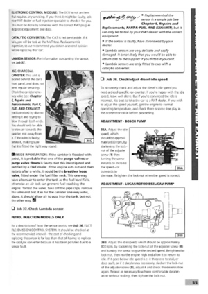 51
51 52
52 53
53 54
54 55
55 56
56 57
57 58
58 59
59 60
60 61
61 62
62 63
63 64
64 65
65 66
66 67
67 68
68 69
69 70
70 71
71 72
72 73
73 74
74 75
75 76
76 77
77 78
78 79
79 80
80 81
81 82
82 83
83 84
84 85
85 86
86 87
87 88
88 89
89 90
90 91
91 92
92 93
93 94
94 95
95 96
96 97
97 98
98 99
99 100
100 101
101 102
102 103
103 104
104 105
105 106
106 107
107 108
108 109
109 110
110 111
111 112
112 113
113 114
114 115
115 116
116 117
117 118
118 119
119 120
120 121
121 122
122 123
123 124
124 125
125 126
126 127
127 128
128 129
129 130
130 131
131 132
132 133
133 134
134 135
135 136
136 137
137 138
138 139
139 140
140 141
141 142
142 143
143 144
144 145
145 146
146 147
147 148
148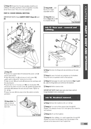 149
149 150
150 151
151 152
152 153
153 154
154 155
155 156
156 157
157 158
158 159
159 160
160 161
161 162
162 163
163 164
164 165
165 166
166 167
167 168
168 169
169 170
170