Page 17 of 171
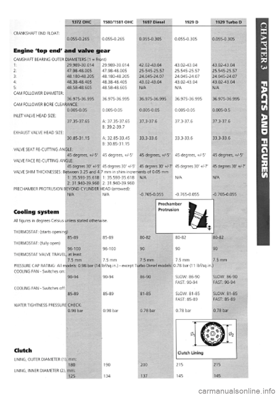
1372 OHC 1580/1581 OHC 1697 Diesel 1929 D 1929 Turbo D
CRANKSHAFT END FLOAT:
0.055-0.265 0.055-0.265
Engine 'top end' and valve gear
CAMSHAFT BEARING OUTER DIAMETERS
(1
= Front)
1: 29.989-30.014
2: 47.98-48.005
48.180-48.205
48.38-48.405
48.58-48.605
CAM FOLLOWER DIAMETER:
36.975-36.995
CAM FOLLOWER BORE CLEARANCE:
0.005-0.05
INLET VALVE HEAD SIZE:
37.35-37.65
EXHAUST VALVE HEAD SIZE:
30.85-31.15
29.989-30.014
47.98-48.005
48.180-48.205
48.38-48.405
48.58-48.605
36.975-36.995
0.005-0.05
A: 37.35-37.65
B: 39.2-39.7
A: 32.85-33.45
B: 30.85-31.15
0.055-0.305
42.02-43.04
25-545-25.57
24.045-24.07
43.02-43.04
N/A
36.975-36.995
0.005-0.05
37.3-37.6
33.3-33.6
VALVE SEAT RE-CUTTING ANGLE:
45 degrees, +/-5' 45 degrees, +/-5' 45 degrees, +/-5'
VALVE FACE RE-CUTTING ANGLE:
45 degrees 30' +/-5' 45 degrees 30' +/-5' 45 degrees 30' +/-7'
VALVE SHIM THICKNESSES: Between 3.25 and 4.7 mm in shim increments of 0.05 mm
1:35.593-35.618 1:35.593-35.618 N/A
2:31.940-39.960 2:31.940-39.960
PRECHAMBER PROTRUSION BEYOND CYLINDER HEAD (arrowed):
N/A N/A -0.765-0.055
0.055-0.305
43.02-43.04
25.545-25.57
24.045-24.07
43.02-43.04
N/A
36.975-36.995
0.005-0.05
37.3-37.6
33.3-33.6
45 degrees, +/-5'
45 degrees 30' +/-7'
N/A
-0.765-0.055
0.055-0.305
43.02-43.04
25.545-25.57
24.045-24.07
43.02-43.04
N/A
36.975-36.995
0.005-0.5
37.3-37.6
33.3-33.6
45 degrees, +/-5'
45 degrees 30' +1-1'
N/A
-0.765-0.055
Cooling system
All figures in degrees Celsius unless stated otherwise.
Prechamber
Protrusion
THERMOSTAT: (starts opening) M^M
85-89 85-89 80-82 80-82
THERMOSTAT: (fully open)
96-100 96-100 90 90
THERMOSTAT VALVE TRAVEL, at least:
7.5 mm 7.5 mm 7.5 mm 7.5 mm
PRESSURE CAP RATING: All models: 0.98 bar (14 Ibf/sq.in.)
-
except Turbo Diesel models: 0.78 bar
(11
Ibf/sq.in.)
COOLING FAN
-
Switches on:
80-82
90
7.5 mm
COOLING FAN
-
Switches off:
90-94
85-89
WATER TIGHTNESS PRESSURE CHECK:
0.98 bar
90-94
85-89
0.98 bar
86-90
81-85
0.78 bar
SLOW: 86-90
FAST: 90-94
SLOW: 81-85
FAST: 85-89
0.78 bar
SLOW: 86-90
FAST: 90-94
SLOW: 81-85
FAST: 85-89
0.78 bar
Clutch
LINING, OUTER DIAMETER (1), mm:
180
LINING, INNER DIAMETER (2), mm:
125
190
134
200
137
Page 18 of 171

1372 OHC 1580/1581 OHC 1697 Diesel 1929 D 1929 Turbo D
Brakes
GAP
-
SERVO PISTON PUSHROD FROM SUPPORT PLATE (d):
22.45-22.65 22.45-22.65 22.45-22.65
MINIMUM ALLOWED FRONT DISC THICKNESS (mm):
NON-ABS: 9.2 NON-ABS: 9.2 NON-ABS: 9.2
ABS: 10.2 ABS: 10.2
MINIMUM ALLOWED REAR DISC THICKNESS
-
when applicable
-
(mm):
9.2 9.2 9.2
MINIMUM ALLOWED BRAKE DRUM INTERNAL DIAMETER
-
when applicable
-
(mm):
181.35 A: 181.35
B: 230
Running gear/suspension - front
CAMBER (not adjustable):
-20' to 40' -20' to 40'
A: 181.35
B: 230
-20' to 40
22.45-22.65
10.2
ABS: 9.2
230
22.45-22.65
10.2
(TdsX: 10.8)
ABS: 9.2
230
-20' to 40' -20 to 40'
(TdsX: 25'
+/-
30')
FRONT CASTER (not adjustable):
1 degree 50'-2 degrees 50'
1
degree 50'-2 degrees 50'
1
degree 50'-2 degrees 50'
1
degree 50'-2 degrees 50' 1 degree 50'-2 degrees 50'
(TdsX: 2 degrees 50')
TOE-IN (adjustable)
-1
to
1
mm
-1
to
1
mm
-1
to
1
mm
-1
to
1
mm
FRONT SPRING HEIGHT RELEASED (mm):
432 EARLY: 432 461 EARLY: 489
TEMPRA: 444 LATE: 444 LATE: 472
TEMPRA: 489
FRONT SPRING: when the given load in Nm is applied, the spring height should equal 191 mm:
3020-3330 3020-3330 3310-3590 3600-3900
REPLACEMENT FRONT SPRING COLOURS: If new springs fail to give the above heights, YELLOW SPRINGS give LOWER heights;
GREEN springs give HIGHER. ALWAYS use them in pairs of same colour.
Rear suspension
CAMBER (not adjustable):
TOE-IN (not adjustable):
-1
to
1
mm
EARLY: 489
LATE: 472
TEMPRA: 493
3600-3900
-1 degree 30' to -30' -1 degree 30' to -30' -1 degree 30' to -30' -1 degree 30' to -30'
-3
to
1
mm
-3
to
1
mm
-3
to
1
mm -3 to
1
mm
-1 degree 30' to -30'
(TdsX: 1 degree 30' +/-15'
-3
to
1
mm
(TdsX:
-2
to 2 mm)
REAR COIL SPRING HEIGHT, RELEASED (mm):
3270 3270 3270 3270 3270
TEMPRA: 3390 TEMPRA: 3390 TEMPRA: 3390 TEMPRA: 3390
REAR COIL SPRING HEIGHT, LOAD in NM REQUIRED TO COMPRESS TO 195 mm.
2930-3170 2930-3170 2930-3170 2930-3170 2930-3170
TEMPRA: 3120-3380 TEMPRA: 3120-3380 TEMPRA: 3120-
3380 TEMPRA: 3120-3380
REPLACEMENT REAR SPRING COLOURS: If new springs fail to give the above heights, YELLOW springs give LOWER heights;
GREEN springs give HIGHER. ALWAYS use them in pairs of same colour.
(*) The bolt need not be greased
Page 19 of 171

PART F: TORQUE WRENCH SETTINGS
Key for engine types and sizes: A
-
1372cc; B
-
1581cc;
C
-
1697cc Diesel; D
-
1929cc Diesel; E
-
1929cc Turbo Diesel.
Engine
Screw retaining caps to crankcase (M10 x 1.25)
Screw retaining intermediate and central caps to crankcase (M12 x 1.25)...
Self-locking screw retaining front and rear caps to crankcase (M12 x 1.25)
Bolt, cylinder head to engine block (M10 x 1.25)
IMPORTANT NOTE: All torque settings shown in
Newton-meters (Nm). Bolt, nut or screw sizes in
brackets in left-hand column.
Bolt, cylinder head to engine block (M12 x 1.25)
Bolts, top to bottom cylinder head (M8)
Nut for connecting rod cap retaining bolt (M9 x 1)
Screw, connecting rod cap (M10 x 1)
Screw retaining engine vent to crankcase
(M8)
(M8)
Screw retaining front cover to crankcase
(MlOx 1.25)
(M8)
Bolt retaining rear cover (flywheel side) to crankcase (M6)
Nut retaining inlet and exhaust ducts to cylinder head
(M8)
(M8)
Screw, flywheel to crankshaft
(M10x 1.25)
(M12
x
1.25)
Lower belt cover retaining screw (M8)
Screw, damping flywheel to drive gear (M8)
Nut retaining auxiliary drive pulley to crankshaft (M20 x 1.25)
Screw retaining drive shaft to crankshaft (*) (M14 x 1.5 left)
Screw, timing gears
(M10x 1.25)
(M12x 1.25)
Belt tensioner retaining bolt
(M8)
(M10x 1.25)
Fixed belt tensioner retaining screw (M10 x 1.25)
Screw retaining auxiliary component driven gear (oil pump) (M10 x 1.25)
Nut for camshaft cap retaining stud (M8)
Nut retaining camshaft and air vacuum pump end mounts (M8)
Combustion prechamber retaining ring (M32 x 1.5)
Nut, injection pump stud (M8)
Screw, injection pump (M8)
Nut fastening flexible block to coolant pump case (M12 x 1.25)
Nut, injection pump gear (M12 x 1.75)
Screw retaining reaction bracket to oil filter support and injection pump (M8).
Top retaining screw or nut, oil filter support and injection pump (M12 x 1.25)
Lower retaining screw, oil filter support and injection pump (M10 x 1.25)
Complete injector (M24 x 2)
Glow plugs (M12 x 1.25)
Nuts retaining fuel delivery line to injection pump and injector (M12 x 1.25)...
Bolt, coolant pump to engine block (M8 x 1)
Bolt retaining cover and bracket to coolant pump case (M8)
Oil pressure switch (M14 x 1.5)
Coolant temperature sender unit
(M16 x 1.5 tapered)
(M18x 1.5 tapered)
Coolant temperature thermal switch (M16 x 1.5 tapered)
(*) The bolt need not be greased.
A B C D E Torque (Nm)
• • 80
• • • 113
• • • 113
• • 40
+
90 degrees
+ 90 deqrees
• • • 100
+
90 degrees
+ 90 deqrees
• • 28
• • 51
• • • 25 + 50 deqrees
• •
• • •
25
20
• • 50
25
• 10
• •
• • •
28
25
• •
• • •
83
142
• • 25
• • • 28
• • 155
• • • 190
• •
• • •
83
118
• •
• • •
25
44
• • • 44
• • 83
• • • 19
• • • 19
• • • 118
• • • 25
• • • 25
• • 80
• • • 49
• • • 29
• • • 98
• • • 71
• • • 55
• • • 15
• • • 29
• • • 25
• • • 23
32
• •
• • • 34
30
• • 30
expert22 fl/i* http://rutracker.org 23
Page 20 of 171

Thermal valve on inlet manifold
(M10 x 1.25 tapered)
(M8 x 1.25 tapered)
Oil pressure sending unit (M14 x 1.5)
Oil temperature sender unit (M14 x 1.5 tapered)....
Oil level sending unit (M12 x 1.25)
Engine oil sump retaining bolt/nut (M6)
Screw retaining oil sealing cover to crankcase (M6)
Nut retaining manifold support bracket (M8)
Nut retaining turbine to exhaust manifold (M8)
Air pressure switch on inlet manifold (M12 x 1.5)...
Power Unit Mounting
ENGINE SIDE
Screw (with long flange) retaining flexible block to rail (M8)
Self-locking nut with plastic ring (for through screw) retaining flexible block
to engine bracket (M10 x 1.25)
Screw retaining flexible block supporting bracket to crankcase
(M10. 1.25)
(M12 x 1.25)
Bolt retaining flexible block to engine bracket (M12 x 1.25)
Bolt retaining power unit suspension link (M10 x 1.25)
GEARBOX SIDE
Screw (with wide flange) retaining flexible block to rail (M8)
Flanged screws retaining support to plate on gearbox (M10 x 1.25)
Self-locking nut with plastic ring (for through screw) retaining flexible block
to gearbox side bracket (M10 x 1.25)
Flanged screw retaining flexible block to gearbox side bracket (M12 x 1.25).
DIFFERENTIAL SIDE
Screw with flange unit retaining elastic block to beam (M8)
Self-locking nut retaining bracket to gearbox support
(M8)
(M12 x 1.25)
Screw retaining bracket brace to support on gear case (M10 x 1.25)
Screw, rubber block to bracket (M12 x 1.25)
Exhaust
Nut retaining flange to exhaust manifold (M8)
Nuts for bolts fastening collars joining exhaust pipe sections (M10 x 1.25)...
Bolt retaining exhaust pipe sleeve to turbine (M8)
Bolt retaining front exhaust pipe section to gearbox (M8)
Metex joint to nut and stud manifold to plate and spring retainer (M8)
Nut for bolt anchoring first exhaust pipe section (M8)
Nut retaining bracket anchoring first exhaust pipe section (M12 x 1.25)
Screw with normal flange retaining exhaust pipe terminal block
support bracket (M8)
Fuel Circuit
Bolt (with wide flange) retaining tank and fitting to body (M8)
Ring retaining delivery, recirculation and vent fitting mounts to tank
(131 x 6-Trapezoid thread)
Screw (with wide flange) retaining fuel filter support bracket (M8)
Page 21 of 171
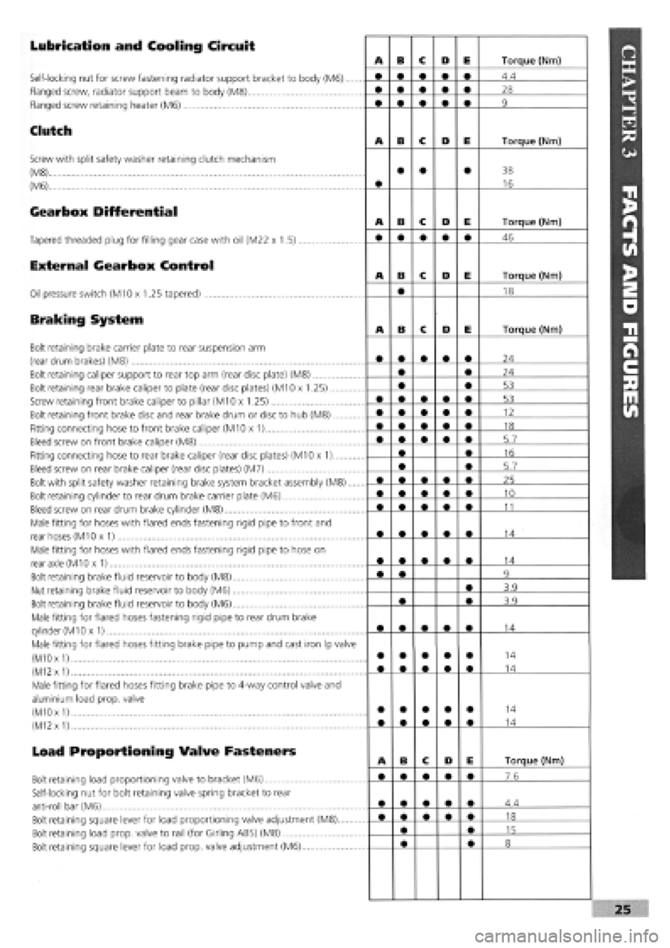
Lubrication and Cooling Circuit
Self-locking nut for screw fastening radiator support bracket to body (M6)....
Flanged screw, radiator support beam to body (M8)
Flanged screw retaining heater (M6)
Clutch
Screw with split safety washer retaining clutch mechanism
(M8)
(M6)
Gearbox Differential
Tapered threaded plug for filling gear case with oil (M22 x 1.5)
External Gearbox Control
Oil pressure switch (M10 x 1.25 tapered)
Braking System
Bolt retaining brake carrier plate to rear suspension arm
(rear drum brakes) (M8)
Bolt retaining caliper support to rear top arm (rear disc plate) (M8)
Bolt retaining rear brake caliper to plate (rear disc plates) (M10 x 1.25)
Screw retaining front brake caliper to pillar (M10 x 1.25)
Bolt retaining front brake disc and rear brake drum or disc to hub (M8)
Fitting connecting hose to front brake caliper (M10 x 1)
Bleed screw on front brake caliper (M8)
Fitting connecting hose to rear brake caliper (rear disc plates) (M10 x 1)
Bleed screw on rear brake caliper (rear disc plates) (M7)
Bolt with split safety washer retaining brake system bracket assembly (M8)....
Bolt retaining cylinder to rear drum brake carrier plate (M6)
Bleed screw on rear drum brake cylinder (M8)
Male fitting for hoses with flared ends fastening rigid pipe to front and
rear hoses (M10 x 1)
Male fitting for hoses with flared ends fastening rigid pipe to hose on
rear axle (M10 x 1)
Bolt retaining brake fluid reservoir to body (M8)
Nut retaining brake fluid reservoir to body (M6)
Bolt retaining brake fluid reservoir to body (M6)
Male fitting for flared hoses fastening rigid pipe to rear drum brake
cylinder
(M1
Ox 1)
Male fitting for flared hoses fitting brake pipe to pump and cast iron Ip valve
(M10
x
1)
(M12
x
1)
Male fitting for flared hoses fitting brake pipe to 4-way control valve and
aluminium load prop, valve
(M10 x
1)
(M12
x
1)
Load Proportioning Valve Fasteners
Bolt retaining load proportioning valve to bracket (M6)
Self-locking nut for bolt retaining valve spring bracket to rear
anti-roll bar (M6)
Bolt retaining square lever for load proportioning valve adjustment (M8)
Bolt retaining load prop, valve to rail (for Girling ABS) (M8)
Bolt retaining square lever for load prop, valve adjustment (M6)
Page 22 of 171

Handbrake Control
Screw with broad flange retaining handbrake and gear lever to body (M8)
Bolt retaining handbrake and gearlever to body (M8)
Screw with normal flange retaining handbrake lever bracket to plate (M8)
Screw with normal flange retaining handbrake cable slide plate to
floorpan (M6)
Screw with long flange for fastening handbrake cable reaction bracket to
floor (M8)
Screw with broad flange retaining pedal unit to dashboard (M8)
Self-locking nut for bolt retaining brake servo to pedal unit (M8)
Nut for through screw joining brake and clutch pedals to pedal unit (M8).
Self-locking nut retaining accelerator pedal to pedal unit (M6)
Nut retaining brake pump to brake servo (M8)
Steering
Self-locking nut retaining steering link ball pin to cast iron pillar (M10 x 1.25)..
Bolt retaining steering and/or power steering box to front beam (M10 x 1.25).
Nut for side steering link (M12 x 1.25)
Self-locking nut retaining steering shaft universal joint forks (M8)
Self-locking nut retaining steering wheel to column (M16 x 1.5)
Bolt retaining steering column mount to body (M6)
Self-locking nut for steering wheel position adjustment device (tighten nut
to specified torque with lever in locked position) (M12 x 1.25)
Nut for screw retaining steering column to support (M8)
Self-locking nut with polyamide ring retaining damper to steering box (M8)
Union for oil delivery fitting from pump to power steering, on power
steering (M14 x 1.5)
Union for adjustable oil delivery fitting from pump to p.s., on power
steering (M16 x 1.5)
Union for oil delivery fitting from power steering to reservoir (M12 x 1.5)
Union oil return fitting from reservoir to pump (M18 x 1.5)
Front Suspension
Screw with broad flange retaining front of front beam to body
(M12 x 1.25)
Screw with normal flange for nut retaining rear of front beam to body
(M10
x
1.25)
Screw with flat and tapered washer for nut retaining front and rear ext.
of wishbone connection plates to beam (M10 x 1.25)
Screws with flat and tapered washer for nut retaining front and rear inner
swinging arm connection plates to beam (M10 x 1.25)
Flanged nut fastening top of damper to block (M12 x 1.25)
Screw with broad flange retaining top damper block to body (M8)
Self-locking nut retaining damper to pillar (M10 x 1.25)
Self-locking nut for screw retaining wishbone head and joint to pillar
(M10
x
1.25)
Screw with tapered and flat safety washer retaining stabilizer bar
support plate to beam (M8)
Self-locking nut retaining end of anti-roll bar to rod (M10 x 1.25)
Self-locking nut retaining bar to front suspension arm (M10 x 1.25)
Nut retaining front wheel hub to coupling
(M22 x 1.5)i
(M24
x
1.5)
Wheel stud (M12 x 1.25).....
Rear Suspension
Screw with broad flange retaining front flexible block to rear subframe
(M12 x 1.25)
A B C D E Torque (Nm)
• • • • • 28
• • • • • 15
• • • • • 28
8.5
35
32
15
32
4.4
20 .
A B C D E Torque (Nm)
• • • • • 34
70
34
• • • • • 20
50
7.4
24
24
15
30
35
20
34
A B c D E Torque (Nm)
108
80
69
69
100
40
70
70
40
70
31
• • • • • •
24
28
86
A B c D E Torque (Nm)
108
Page 23 of 171
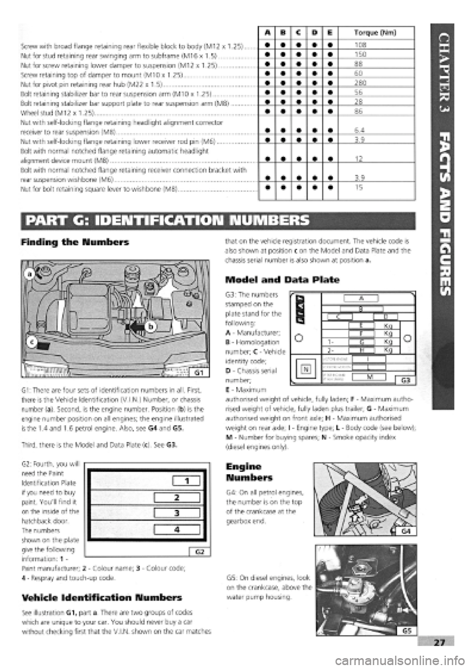
Screw with broad flange retaining rear flexible block to body (M12 x 1.25)..
Nut for stud retaining rear swinging arm to subframe (M16 x 1.5)
Nut for screw retaining lower damper to suspension (M12 x 1.25)
Screw retaining top of damper to mount (M10 x 1.25)
Nut for pivot pin retaining rear hub (M22 x 1.5)
Bolt retaining stabilizer bar to rear suspension arm (M10 x 1.25)
Bolt retaining stabilizer bar support plate to rear suspension arm (M8)
Wheel stud (M12 x 1.25)
Nut with self-locking flange retaining headlight alignment corrector
receiver to rear suspension (M8)
Nut with self-locking flange retaining lower receiver rod pin (M6)
Bolt with normal notched flange retaining automatic headlight
alignment device mount (M8)
Bolt with normal notched flange retaining receiver connection bracket with
rear suspension wishbone (M6)
Nut for bolt retaining square lever to wishbone (M8)
A B c D E Torque (Nm)
• • • • • 108
• • • • • 150
• • • • • 88
• • • • • 60
• • • • • 280
• • • • • 56
• • • • • 28
• • • • • 86
• • • • • 6.4
• • • • • 3.9
• • • • • 12
• • • • • 3.9
• • • • • 15
PART G: IDENTIFICATION NUMBERS
Finding the Numbers
G1: There are four sets of identification numbers in all. First,
there is the Vehicle Identification (V.I.N.) Number, or chassis
number (a). Second, is the engine number. Position (b) is the
engine number position on all engines; the engine illustrated
is
the 1.4 and 1.6 petrol engine. Also, see G4 and G5.
Third, there is the Model and Data Plate (c). See G3.
G2: Fourth, you will
need the Paint
Identification Plate
if you need to buy
paint. You'll find it
on the inside of the
hatchback door.
The numbers
shown on the plate
give the following
information: 1 -
Paint manufacturer; 2
-
Colour name; 3
-
Colour code;
4
-
Respray and touch-up code.
Vehicle Identification Numbers
See illustration G1, part a. There are two groups of codes
which are unique to your car. You should never buy a car
without checking first that the V.I.N, shown on the car matches
that on the vehicle registration document. The vehicle code is
also shown at position c on the Model and Data Plate and the
chassis serial number is also shown at position a.
Model and Data Plate
G3: The numbers
stamped on the
plate stand for the
following:
A
-
Manufacturer;
B
-
Homologation
number; C
-
Vehicle
identity code;
D
-
Chassis serial
number;
E
-
Maximum
authorised weight of vehicle, fully laden; F
-
Maximum autho-
rised weight of vehicle, fully laden plus trailer; G
-
Maximum
authorised weight on front axle; H
-
Maximum authorised
weight on rear axle; I
-
Engine type; L
-
Body code (see below);
M - Number for buying spares; N
-
Smoke opacity index
(diesel engines only).
Engine
Numbers
G4: On all petrol engines,
the number is on the top
of the crankcase at the
gearbox end.
G5: On diesel engines, look
on the crankcase, above the
water pump housing.
1
2
3
4
G2
r
B
r
B I B I
r
B
C I D I
r
B
I E I Kn
o o I F I Kq o o 1- I <3 I Kq o o
2- | H I Kq
o
MOTORE ENGINE
I I
N VERSIONE-VERSION •f
PER RICAM8:
N*
FOR SPARED
L I
1 G3
Page 24 of 171

Please read the whole of the CHAPTER 1, SAFETY FIRST! before carrying out any work on your car.
fUADTCSA I En Hr
GETTIIMG THROUGH THE MOT
This chapter is for owners in Britain whose
vehicles need to pass the 'MoT' test.
Obviously, you won't be able to examine
your car to the same degree of
thoroughness as the MoT testing station.
But you can reduce the risk of being one of
the 4 out of 10 who fail the test first time by
following this check-list.
iMFTri
The checks shown below are correct at the
time of writing but do note that they are
becoming stricter all the time. Your local
MoT testing station will have the latest
information, should you need it.
1 p Chapter Contents -
Page No. Page No.
PART A: INSIDE THE CAR 28 PART C: VEHICLE RAISED OFF THE GROUND 30
PART B: VEHICLE ON THE GROUND 29 PART D: EXHAUST EMISSIONS 31
PART A: INSIDE THE CAR
Steering Wheel and Column
O 1. Try to move the steering wheel towards and away from you and then from side to side. There should be no appreciable movement or play. Check that the steering wheel is not loose on the column.
02 . Lightly grip the steering wheel between thumb and finger and turn from side to side. Cars with a steering rack: free play should not exceed approximately 13 mm (0.5 in.), assuming a 380 mm (15 in.) diameter steering wheel. Cars fitted with a steering box: free play should not exceed approximately 75 mm (3.0 in.), assuming a 380 mm (15 in.) diameter steering wheel.
Ob . If there is a universal joint at the bottom of the steering column inside the car, check for movement. Place your hand over the joint while turning the steering wheel to-and-fro a little way with your other hand. If ANY free play can be felt, the joint must be replaced.
04. Ensure that there are no breaks or loose components
on the steering wheel itself.
Electrical Equipment
OS . With the ignition turned on, ensure that the horn works okay.
OE . Check that the front wipers work.
07 . Check that the windscreen washers work.
o 8. Check that the internal warnings for the indicator and hazard warning lights work okay.
Checks With An Assistant
O9 . Check that the front and rear side lights and number plate lights work and that the lenses and reflectors are secure, clean and undamaged.
o 10. Check the operation of the headlights (you won't be able to check the alignment yourself) and check that the lenses are undamaged. The reflectors inside the headlights must not be tarnished, nor must there be condensation inside the headlight.
o 11. Turn on the ignition and check the direction
indicators, front and rear and on the side markers.
o 12. Check that the hazard warning lights operate on the
outside of the vehicle, front and rear.
o 13. Check that the rear fog light/s, including the warning
light inside the car, all work correctly.
o 14. Check that the rear brake lights work correctly. These checks are carried out all around the vehicle with all four wheels on the ground.
o 15. Operate the brake lights, side lights and each indicator in turn, all at the same time. None should affect the operation of the others.
SAFETY FIRST!
• Follow the Safety information in CHAPTER 1, SAFETY FIRST! but bear in mind that the vehicle needs
to be even more stable than usual when raised off the ground.
• There must be no risk of it toppling off its stands or ramps while suspension and steering components
are being pushed and pulled in order to test them.
 1
1 2
2 3
3 4
4 5
5 6
6 7
7 8
8 9
9 10
10 11
11 12
12 13
13 14
14 15
15 16
16 17
17 18
18 19
19 20
20 21
21 22
22 23
23 24
24 25
25 26
26 27
27 28
28 29
29 30
30 31
31 32
32 33
33 34
34 35
35 36
36 37
37 38
38 39
39 40
40 41
41 42
42 43
43 44
44 45
45 46
46 47
47 48
48 49
49 50
50 51
51 52
52 53
53 54
54 55
55 56
56 57
57 58
58 59
59 60
60 61
61 62
62 63
63 64
64 65
65 66
66 67
67 68
68 69
69 70
70 71
71 72
72 73
73 74
74 75
75 76
76 77
77 78
78 79
79 80
80 81
81 82
82 83
83 84
84 85
85 86
86 87
87 88
88 89
89 90
90 91
91 92
92 93
93 94
94 95
95 96
96 97
97 98
98 99
99 100
100 101
101 102
102 103
103 104
104 105
105 106
106 107
107 108
108 109
109 110
110 111
111 112
112 113
113 114
114 115
115 116
116 117
117 118
118 119
119 120
120 121
121 122
122 123
123 124
124 125
125 126
126 127
127 128
128 129
129 130
130 131
131 132
132 133
133 134
134 135
135 136
136 137
137 138
138 139
139 140
140 141
141 142
142 143
143 144
144 145
145 146
146 147
147 148
148 149
149 150
150 151
151 152
152 153
153 154
154 155
155 156
156 157
157 158
158 159
159 160
160 161
161 162
162 163
163 164
164 165
165 166
166 167
167 168
168 169
169 170
170


