1988 FIAT TEMPRA alternator belt
[x] Cancel search: alternator beltPage 30 of 171

PART G: BRAKING SYSTEM
Job 49. Check front brakes
Job 50. Check rear brakes
Job 51. Check/adjust handbrake
Job 52. Check brake pipes
Job 53. Change brake hydraulic fluid
SERVICE INTERVALS
C
C
C
C
E
Job 56. Check seat and seat belt mountings C
Job 57. Check headlight alignment C
Job 58. Check underbody C
Job 59. Check spare tyre B
Job 60. Change pollen filter C
Job 61. Replace airbag gas generator 10 years
PART I: ROAD TEST
PART H: BODYWORK & INTERIOR
Job 54. Lubricate hinges and locks
Job 55. Check windscreen
Job 62. Road test and specialist check. AFTER EVERY
SERVICE
ENGINE BAY LAYOUTS
These are the engine bay layouts common to almost all Tipo/Tempras. Note that there is no carburettor fitted to fuel-injected
vehicles.
1 - PETROL ENGINES 2 - DIESEL ENGINES
1
-
oil filler cap 7
-
distributor (ignition) 12 - oil filter location
2
-
engine oil dipstick 8
-
coil (ignition) 13
-
fuel pump (mechanical)
3
-
coolant filler cap 9
-
electronic control unit (ECU), 14
-
diesel injection pump
4 - brake fluid reservoir Digiplex 2 15
-
alternator location (behind engine)
5 - battery 10
-
air filter housing
6
-
screenwash reservoir cap 11
-
fuel filter
PART A: REGULAR CHECKS
1B. ...and the diesel's
dipstick is in a similar
spot, located at the
front edge of the
timing cover, behind
the right-hand
headlight.
Q INSIDE INFORMATION: The
difference between MIN and MAX
marks is approximately one litre of
oil. Q
We recommend that these Jobs are carried out on a weekly
basis, as well as before every long journey. They consist of
checks essential for your safety and for your car's reliability.
• Job 1. Engine oil
-
check level.
Check the engine oil level with the car on level ground. If the
engine has been running, leave it turned off for several
minutes to let the oil drain into the sump.
1A. All petrol engines
have the dipstick at
the front of the block,
towards the timing
belt end...
1C. Lift the dipstick out,
wipe it dry and re-insert it. The oil
level is correct when between the
MAX and MIN marks.
Page 45 of 171

FACT FILE: DIGIPLEX DISTRIBUTOR
REMOVAL
25E. If the distributor has to be removed
for any reason, it is ESSENTIAL that the
PRECISE position of the rotor arm in
relation to the distributor body and the
position of the distributor body (2) in relation to the
cylinder head
-
via the spacer (1)
-
are clearly marked so
that they can be
replaced in
EXACTLY the
same position.
Note that the
locator
(arrowed) only
gives an approx-
imate, not a
precisely correct
location of the
spacer.
25F. D INSIDE
INFORMATION:
Use
touch-up
paint
and
let it
dry before
removing the
unit. D
SETTING THE RPM AND TDC SENSOR POSITION
25G. This job can not
be carried out without
the FIAT special tool
illustrated. The sensor
is correctly positioned
when the engine is
produced and to
prevent accidental
tampering, one of the
two bolts holding the
sensor in place is a
shear bolt and will have to be renewed if removed.
IMPORTANT NOTE: The slots in the distributor body are
NOT used to alter the advance setting, as on a conven-
tional distributor. This operation is carried out by the
position of the TDC sensor
-
see later.
CHECKING THE IGNITION ADVANCE can be carried out in an
approximate manner using the same method as described in
25C.
However, you must make sure that the following steps
are
taken:
•
the
vacuum pipe between the electronic control unit and
the
inlet manifold must remain connected and be in good
condition
-
neither blocked nor split.
•
the
engine must be at its normal operating temperature.
•
the
idle speed/mixture/CO adjustments must be correct
-
see Job 35.
•
with
the engine idling at between 800 and 900 rpm, the
mark on
the crankshaft pulley should be at approximately 12
degrees BTDC.
IMPORTANT NOTE: The only marks are for 0, 4 and 10
degrees BTDC, so you will have to make a guess at the
correct position for 12 degrees.
FACT FILE: TIMING MARKS
y-; • It appears that some earlier engines
H. j may be fitted with different types of
J timing marks. There might be a metal
pointer fitted to the timing belt cover.
Other engines may have their timing marks in the
flywheel housing, so that you need to take out a rectan-
gular rubber bung and look out for the fixed timing
mark on the flywheel housing and the timing settings
on
the flywheel itself.
• It always helps to paint all of the timing marks with
white paint or typists' correction fluid so that they are
easier to see when the timing light is operating.
1. Line up the mark on the crankshaft pulley with the 0
degrees (TDC) mark on the timing belt cover. See 25C.
2. Without moving the crankshaft from this position, undo the
screws holding the rpm and TDC sensor to the sensor carrier
plate. Fit the tool no. 1895898000 in place of the sensor.
Check that the flywheel pin or lug (3) must fit in the groove of
the tool and the bolts must tighten easily. If not, carry out the
following procedure:
3. Slacken the bolts securing the carrier plate behind the
sensor.
4. Move the plate so that the tool slips freely into the sensor's
hole and the bolts tighten easily.
5. Tighten the bolts holding the sensor carrier plate in place.
6. Remove the tool and refit the sensor.
ON BOTH TYPES: As the distributor is turned (clockwise to
advance, anti-clockwise to retard), the timing mark on the
flywheel will be seen to move relative to the pointers. Move
the distributor so the timing marks are aligned correctly, and
retighten the clamp nut or bolts.
• Job 26. Check/adjust drive belt/s.
26A. Depending on
your Tipo or Tempra
model, access to the
alternator belt and
adjustment fixings will
probably be possible
from the engine bay.
V-BELTS ONLY
Check the belt, and if there is any sign of cracking, 'polishing',
fraying or severe wear on the inner face, replace it. The belt
should deflect by about 10 mm when firm thumb pressure is
applied to the belt between the pulleys in the direction of the
arrow. Too little tension and the belt might slip; too much,
and belt and bearing wear will increase.
Page 46 of 171

26B. If adjustment is
necessary, slacken the
tensioning nut (A) and
the alternator pivot (B),
on all models. (These
are two typical
layouts.)
Use a length of wood
to pivot the alternator
away from the engine
block but take great
care not to damage the
alternator casing.
Tighten the nuts/bolts
when the tension is correct.
RIBBED BELTS ONLY
If your vehicle is fitted with a ribbed belt, pivot the alternator
as described above and tighten it when you can just twist the
belt by 1/4 turn in the middle of its longest run.
IMPORTANT NOTE:
• Belt tension should only be adjusted when the engine
is cold.
• After adjustment, run the engine for 15 to 30 seconds,
to allow the belt to bed-in, then check again.
• Experience mechanics claim that belts often go slack
when the engine heats up, producing belt squeal.
• If this happens on your vehicle, adjust the belt again
when the engine is hot. Wear industrial leather gloves
and long-sleeved overalls and take very great care not to
burn yourself on the hot engine or exhaust.
If there is an auxiliary unit, such as an air conditioning pump,
driven by a separate drive belt, examine and adjust it as
described here.
Q Job 27. Check electric fan operation.
Drive the car until it is at normal operating temperature. Park
outdoors and, with the gearbox in neutral (or 'P' in the case of
an automatic) leave the engine running. At just above normal
temperature the electric cooling fan should come on, and
then go off again when the temperature drops. Refer to your
temperature gauge, if fitted. If the fan doesn't behave, check
the thermo-switch on the radiator, along with all connections
and wires in its circuit with the fan motor. See Job 13 and
Chapter
6,
Repairs and Replacements.
• Job 28. Run diagnostic ignition/injection test.
DIAGNOSTIC TEST
28A. Have your FIAT dealer
carry out a diagnostic test,
plugging his tester into the
diagnostic socket tucked away
at the front of the passenger-
side footwell.
EMISSIONS TESTS
Vehicles fitted with the Mono-Jetronic fuel injection system
are not fitted with adjustment screws. The system is self-
regulating. However, specified annual checks carried out with
an exhaust gas analyser will provide essential information on
the condition of the injection/ignition system, the catalytic
converter and the engine itself.
28B. The checks are carried out twice: once with the test
sensor at least 300 mm into the end section of the exhaust
pipe (a). (If the shape of the end section of the exhaust pipe is
such that the sensor cannot be completely introduced, a
special extension pipe must be added ensuring that the joint
with the car's tail-pipe is sealed.); the second after undoing
the cap or nut on the exhaust pipe upstream of the catalytic
converter (b).
The following table shows the test limits for carbon monoxide,
unburned hydrocarbons (in parts per million) and carbon
dioxide:
CO (%) HC (p.p.m.) C02(%)
Upstream of the catalyzer (a) 0,4 -h 1 500/600* >12
Downstream of the catalyzer (b)
=£
0,35 =s 90 >13
* FIAT's figures vary.
IMPORTANT NOTE: The engine must be at its normal
operating temperature and normal tick-over speed.
• if the percentage concentration of CO upstream of the
catalytic converter is not within the limits in the table,
check:
• the Lambda sensor
-
see Job 37.
• air penetration around the Lambda sensor housing.
• faults in the ignition or injection systems. (First try
renewing the spark plugs, distributor cap and HT leads.)
If, at the same time, the concentration of hydrocarbons
is not less than 500/600 parts per million (FIAT'S figures
vary), check:
• the ignition timing (see Job 25).
• the valve clearances (see Job 9).
• the valve gear timing (see Job 12).
• the engine compression. (You will need to remove the
spark plugs, fit a compresson tester to each plug
aperture in turn and crank the engine. See the FACT FILE
on page 51.)
Page 61 of 171

PART A: ENGINE
PART A: Contents
Job 1. Petrol engine. Timing belt
-
replacement and Job 12. Petrol engine. Mountings
-
replacement.
adjustment. Job 13. Diesel engine. Timing belt
-
replacement and
Job 2. Petrol engine. Cylinder head
-
removal. adjustment. •
Job 3. Petrol engine. Cylinder head and camshaft housing -Job 14. Diesel engine. Cylinder head
-
removal.
refitting. Job 15. Diesel engine. Cylinder head
-
refitting.
Job
4.
Petrol engine. Cylinder head
-
dismantling and Job 16. Diesel engine. Cylinder head
-
overhaul.
overhauling. Job 17. Diesel engine. Valve clearances
-
adjustment.
Job 5. Petrol engine
-
dismantling. Job 18. Diesel engine
-
removal.
Job
6.
Petrol engine
-
checking and reassembly. Job 19. Diesel engine
-
refitting.
Job
7.
Petrol engine. Valve clearances
-
adjustment. Job 20. Diesel engine. Mountings
-
replacement.
Job 8. Petrol engine/transmission
-
removal. Job 21. Diesel engine/transmission (removed from car)
-
Job
9.
Petrol engine/transmission
-
refitting. separation.
Job 10. Petrol engine/transmission (removed from car)
-
Job 22. Diesel engine/transmission (removed from car)
-
separation. reconnection.
Job 11. Petrol engine/transmission (removed from car)
-
Job 23. Diesel engine
-
dismantling.
reconnection. Job 24. Diesel engine
-
reassembly.
Job 1. Petrol engine. Timing belt
- replacement and adjustment.
Mi*^^ Zc+sc, / • The crankshaft pulley nut
n^^ will be difficult to turn.
• If the engine is in the car,
engage a gear (or 'Park' in the case of an automatic)
and have an assistant hold the footbrake down very
firmly. This will stop the engine from turning.
• Alternatively, with the starter motor removed, you
can have a helper prevent the flywheel ring gear from
turning with a large screwdriver.
• Step 4: Before removing the belt, put the pulley nut back
onto the crankshaft, take the car out of gear (if the engine is
still in the car) and remove the spark plugs. You can now turn
the engine in a clockwise direction using the refitted crank
pulley nut
-
without the pulley, of course!
• Step 5A: With
the timing belt still in
place, turn the engine
so that the timing
mark on the camshaft
sprocket lines up with
the one on the front
cover. On some
engines, the front
cover looks like this...
• Step 5B:
...while on the
majority, it looks
like this. The top
part of the cover
backplate slides
out so that the
plastic pip is level
with the camshaft
sprocket. Turn
the sprocket so that the timing mark on the sprocket lines up
with this pip.
IMPORTANT NOTE: It is false economy to refit a used
timing belt. If the belt breaks, it will cause complete
engine failure so always fit a new one.
• Step 1:
Disconnect the battery
and
remove the
alternator drivebelt as
described in PART C:
COOLING
SYSTEM
0 Step 2: Take off
the timing
belt cover.
This is held
by a total
of
four bolts (arrowed).
• Step 3: Take off
the
crankshaft pulley
nut and
remove the
pulley.
Page 69 of 171

G Step 17: Now repeat this operation on the remaining
valves.
G Step 18: Wash the whole cylinder head again using
paraffin and an old brush, making sure that all traces of
grinding paste are removed, then dry off. Use compressed air
if
available.
SAFETY FIRST!
•
Treat
compressed air with respect. Always wear
goggles
to protect your eyes.
•
Never
allow the airline nozzle near any of the body Sep apertures.
H INSIDE INFORMATION! Check the height of the valve
springs against new ones if possible, but if not, compare
them with each other. If any are shorter than the others,
play safe and replace the complete set. They are bound
to have suffered fatigue which could cause premature
valve failure. H
G Step 19: To install the valves, start from one end.
Lubricate a valve stem with fresh engine oil and slide it in to its
guide.
G Step 20: Locate a new valve stem seal over the stem of
the valve
(if applicable) and push down into contact with the
guide. Position the seal on its seat using a suitable metal tube.
G Step 21: Refit the flat washer and spring seat.
G Step 22: Position the inner and outer springs and the
spring
cap.
G Step 23: Re-apply the valve spring compressor and
compress
the springs enough to allow you to engage the split
collets
in
the stem grooves.
D INSIDE INFORMATION! Grease the grooves so that the
collets will 'stick' in place. The collets are easily fitted by
'sticking' the backs of them onto the end of a screw-
driver with some grease and feeding them into
position. B
G Step 24: Carefully release the spring compressor and
check
that the collets are correctly located. Tap the end of the
stem with
a hammer, to bed them in.
G Step 25: Fit the remaining valves.
Job 5. Petrol engine -
dismantling.
G Step 1: Familiarise yourself with the layout of the engine.
Refer to
illustration Job
2-1
for an exploded view of the
engine
components.
G Step 2: Drain the engine oil. Remove the cylinder head.
See
Job 2.
G Step 3: Remove the distributor. See PART D: IGNITION
• Step 4:
Remove the petrol
pump and spacer
block, if the
mechanical type
(a). (Electric fuel
pumps are in the
fuel tank.)
• Step 5:
Remove and
discard the oil filter
illustration Job
5-4,
• Step 6: Remove the water pump complete with its distri-
bution pipe, and the power steering pump (if fitted).
Q Step 7: Remove the alternator, the crankshaft pulley, the
crankshaft and camshaft sprockets, the cam belt tensioner
and the cam belt cover backplate.
• Step 8:
Remove the
auxiliary shaft
sprocket...
• Step 9: ...the
end plate and
seal, and remove
the auxiliary shaft.
• Step 10:
Undo and remove
the clutch, and
then the flywheel.
• Step 11: Turr
engine assembly c
remove the sump
and remove the crankcase breather (see
part b) with its pipe.
Page 81 of 171

Job 13. Diesel engine. Timing belt
- replacement and adjustment.
• Step 1: Undo
the bolts and remove
the
top timing belt
cover.
Q Step 2: Securely
support the car and
remove
the right
hand
front wheel for
access
to the wheel
arch
dust shield.
Undo
the fasteners
(arrowed) and
remove
the shield.
• Step 3: Slacken the power steering pump support
bracket securing
bolts (arrowed).
Q Step 4: Slacken
the bolts
holding the
power steering
pump
to the
bracket
(arrowed)
• Step 5: and
remove the drive
belt, allowing it to
hang on the engine
support bracket
(arrowed).
• Step 6: Slacken the alternator mounting bolts, and
remove the drive belt.
• Step 7: Ensure
that the notch on the
crankshaft
pulley/damper
(arrowed) is aligned
with the ridge on the
lower half of the
timing belt cover
(arrowed),
M
V// Job 13-7
• Step 8: .... then
undo the securing
bolts (arrowed) and
remove the cover
(inset).
• Step 9: Undo
the bolts (arrowed)
and remove the
flywheel cover guard
(inset).
IMPORTANT NOTE: From now on, one of two different
procedures will be required, depending upon the age of
your diesel engine, as modifications were made from
engine No. 1723291-on to allow fine adjustment of
camshaft timing. Both procedures require the use of FIAT
special tooling, which it may be possible to hire from
your local specialist
-
otherwise you will have to make
your own tools or have the work carried out for you.
85
Page 82 of 171

PART A
-
ENGINES PRIOR TO ENGINE NO. 1723291 • Step A15: Ease the timing belt off the sprockets.
Gl Step A10: Use a spanner on the crankshaft bolt (a) to
turn the engine until the timing marks on the crankshaft,
camshaft and injection pump sprockets align with their
respective reference marks. Align the crankshaft sprocket with
the notch on the front cover (b). Align the camshaft sprocket
with the hole in the timing belt cover (c). Align the injection
pump sprocket with the reference on the timing belt rear
guard (d).
• Step A11: Use
the FIAT flywheel
lock, part no.
1860766000 (or
construct your own
tool) to stop the
crankshaft from
turning.
• Step A12:
Remove the
alternator belt
pulley/damper.
• Step A13:
Using FIAT tool no.
1842128000 (see illustration Job
13-A10,
parte), lock the
injection pump sprocket to prevent it turning.
• Step A14: Slacken the belt tensioner nut (see illustration
Job
13-A10,
part f), move the tensioner away from the belt
and temporarily lock it in position.
• Step A16: Fit the new belt, first making sure that all of
the timing marks still align.
• Step A17: If you do not have access to the correct FIAT
tensioning tool, release the locknut, push the tensioner firmly
into the belt and lock it up by tightening its bolt.
If you do have the FIAT special tool (a weighted bar), attach it
to the tensioner, which will move to the position of correct
tension. Lock the tensioner bolt. Remove the special tool
locking the injection pump sprocket.
E3 INSIDE INFORMATION: If you can't put enough
pressure on the tensioner with your fingers, carefully use
a long screwdriver as a lever. Alternatively, push a pair of
bolts into the two holes in the tensioner and lever
between them to turn the tensioner. E9
Q Step A18: Rotate the engine through two revolutions. If
the belt is correctly tensioned you should just be able to twist
it through a quarter-turn when gripping it between thumb
and finger in the centre of its longest run between sprockets.
Adjust as necessary.
Q Step A19: Refit the remaining parts in the reverse order,
then check the injection timing (see Chapter
5,
Servicing
Your Car, Job
39)
PART B
-
ENGINES FROM ENGINE NO. 1723291-ON
Job 13-B10
Q Step B10: Turn the crankshaft in its normal direction of
rotation until the marks on the crankshaft sprocket (a) and
fuel injection pump sprocket (b) line up with the fixed marks
on the engine. This will place cylinder No. 1 at Top Dead
Centre TDC and set the camshaft for the power stroke of the
same cylinder. Lock the flywheel (see Step A11) and remove
the alternator belt pulley (see Step A12).
IMPORTANT NOTE: The hole for fixing the camshaft
sprocket (c) has a fine-adjustment slot, so it is possible
that the mark on the sprocket may not line up exactly
with the mark on the cover.
Page 91 of 171
Q Step 2: Before starting the engine, make sure all your
electrical connections are sound and your fuel, oil and coolant
connections are correct and secure.
Q Step 3: Run the engine to working temperature and then
allow to cool. Re-check all fluid levels.
Job 20. Diesel engine.
Mountings - replacement.
See
Job
12
and Job
18,
Step 20
Job 21. Diesel engine/
transmission (removed from car)
- separation.
Q Step 1: Remove the starter motor.
• Step 2: On the turbo version, undo the flange bolts see
Job
18,
Step 16A and withdraw the drive-shaft extension, if
still
fitted.
Q Step 3: Unbolt and remove the rear engine plate and the
gearbox, being careful to support the gearbox weight as it is
withdrawn.
Job 22. Diesel engine/
transmission (removed from car)
- reconnection.
Q Step 1: Before proceeding, check the condition of the
clutch and
its release mechanism. Make sure the driven plate
is
properly centred on the flywheel
-
see PART B: TRANS-
MISSION.
Q Step 2: Now reverse the order of separation, but be
careful when
engaging the gearbox input shaft with the
clutch
driven plate that you don't 'hang' its weight on the
splines.
Also,
see
Job 11.
Job 23. Diesel engine -
dismantling.
This Job should
be read in conjunction with Job 5 The
engines are
broadly similar although the information given in
this Job takes
priority for diesel engines. It is MOST
IMPORTANT that you read the FACT FILE on page 84.
SAFETY FIRST!
•
The inside
of diesel engines are particularly filthy
places!
•
Old diesel
oil
is
carcinogenic!
•
Wear suitable
impervious gloves!
I
• Step 1: Remove the timing belt and cylinder head. See
Jobs
13
and 14.
Q Step 2: Remove the alternator, water pump and
thermostat housing distribution pipe.
• Step 3: Remove the crankshaft timing belt sprocket.
Q INSIDE INFORMATION! Note that the bolt securing
the crankshaft sprocket has a left-hand thread and must
be undone clockwise. D
• Step 4: Unbolt the timing belt tensioner and idler pulleys.
• Step 5: Remove the injection pump sprocket.
Q INSIDE INFORMATION! You will need two FIAT tools
for this operation. One (No. 1860473000) is to prevent
the sprocket from turning when undoing the nut, and
the other (extractor No. 1842128000) to pull the sprocket
from the injection pump shaft. Alternatively it may be
possible to improvise a means of preventing sprocket
rotation, and a suitable three-leg puller may be carefully
used to withdraw the sprocket. Take care not to lose the
pump shaft Woodruff key. B
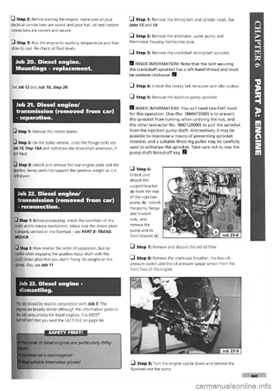
• Step 6:
Unbolt and
detach the
support bracket
(a) from the rear
of the injection
pump (b). Unbolt
the pump flange
and bracket
nuts, and
remove the
pump and its
front bracket (c).
• Step 7: Remove and discard the old oil filter.
Step 8: Remove the crankcase breather, the low-oil-
pressure switch and the oil pressure gauge sensor from the
front face of the engine.
• Step 9: Turn the engine upside down and remove the
flywheel and the sump.