1988 FIAT TEMPRA brake pads
[x] Cancel search: brake padsPage 3 of 171

Mains Electricity
Avoid the use of mains electricity when working on the vehicle,
whenever possible. Use rechargeable tools and a DC inspection
lamp, powered from a remote 12V battery
-
both are much
safer. However, if you do use mains-powered equipment,
ensure that the appliance is wired correctly to its plug, that
where necessary it is properly earthed (grounded), and that the
fuse is of the correct rating for the appliance. Do not use any
mains powered equipment in damp conditions or in the vicinity
of fuel, fuel vapour or the vehicle battery.
Always use an RCD (Residual Current Device) circuit breaker
with mains electricity. Then, if there is a short, the RCD circuit
breaker minimises the risk of electrocution by instantly cutting
the power supply.
Ignition System
Never work on the ignition system with the ignition switched
on, or with the engine being turned over on the starter, or
running and you are recommended never to do so.
Touching certain parts of the ignition system, such as the HT
leads, distributor cap, ignition coil etc., can result in a severe
electric shock or physical injury as a hand is pulled sharply away.
Voltages produced by electronic ignition systems are much
higher than those produced by conventional systems and could
prove fatal, particularly to people with cardiac pacemaker
implants. Consult your handbook or main dealer if in any
doubt.
Cooling Fan
On many vehicles, the electric cooling fan can switch itself on
even with the ignition turned off. This is especially likely after
driving the car and parking it before turning off, after which
heat rises to the top of the engine and turns the fan on,
suddenly and without warning. If you intend working in the
engine bay, it's best to do so when the engine is cold, to
disconnect the battery, or keep away from the fan, if neither of
these are possible.
Battery
Never cause a spark, smoke, or allow a naked light near the
vehicle's battery, even in a well ventilated area. Highly explosive
hydrogen gas is given off as part of the charging process.
Battery terminals on the car should be shielded, since a spark
can be caused by any metal object which touches the battery's
terminals or connecting straps.
IMPORTANT NOTE: Before disconnecting the battery earth
(ground) terminal read the relevant FACT FILE in Chapter 5
regarding saving computer and radio settings.)
When using a battery charger, switch off the power supply
before the battery charger leads are connected or disconnected.
If the battery is not of the 'sealed-for-life' type, loosen the filler
plugs or remove the cover before charging. For best results the
battery should be given a low rate trickle charge overnight. Do
not charge at an excessive rate or the battery may burst.
Always wear gloves and goggles when carrying or when
topping up the battery. Acid electrolyte is extremely corrosive
and must not be allowed to contact the eyes, skin or clothes.
Brakes and Asbestos
Obviously, a car's brakes are among its most important safety
related items. ONLY work on your vehicle's braking system if
you are trained and competent to do so. If you have not been
trained in this work, but wish to carry out the jobs described in
this book, we strongly recommend that you have a garage or
qualified mechanic check your work before using the car.
Whenever you work on the braking system components, or
remove front or rear brake pads or shoes: i) wear an efficient
particle mask; ii) wipe off all brake dust from the brakes after
spraying on a proprietary brand of brake cleaner (never blow
dust off with compressed air); iii) dispose of brake dust and
discarded shoes or pads in a sealed plastic bag; iv) wash your
hands thoroughly after you have finished working on the
brakes and certainly before you eat or smoke; v) replace shoes
and pads only with asbestos-free shoes or pads. Note that
asbestos brake dust can cause cancer if inhaled; vi) always
replace brake pads and/or shoes in complete 'axle' sets of four
-
never replace the pads/shoes on one wheel only.
Brake Fluid
Brake fluid absorbs moisture rapidly from the air and can
become dangerous resulting in brake failure. You should
change the fluid in accordance with your vehicle manufacturer's
recommendations or as advised in this book. Never store (or
use) an opened container of brake fluid. Dispose of the
remainder at your Local Authority Waste Disposal Site, in the
designated disposal unit, not with general waste or with waste
oil.
Engine Oils
Always wear disposable plastic or rubber gloves when draining
the oil from your engine, i) Note that the drain plug and the oil
are often hotter than you expect. Wear gloves if the plug is too
hot to touch and keep your hand to one side so that you are
not scalded by the spurt of oil as the plug comes away; ii) There
are very real health hazards associated with used engine oil. In
the words of one manufacturer's handbook "Prolonged and
repeated contact may cause serious skin disorders, including
dermatitis and cancer." Use a barrier cream on your hands and
try not to get oil on them. Always wear gloves and wash your
hands with hand cleaner soon after carrying out the work. Keep
oil out of the reach of children; iii) NEVER, EVER dispose of old
engine oil into the ground or down a drain. In the UK, and in
most EC countries, every local authority must provide a safe
means of oil disposal. In the UK, try your local Environmental
Health Department for advice on waste disposal facilities.
Plastic Materials
Many of the materials used (polymers, resins, adhesives and
materials acting as catalysts and accelerators) contain dangers in
the form of poisonous fumes, skin irritants, and the risk of fire
Page 55 of 171

REAR SHOCK ABSORBERS • Job 48. Check wheel bolts for tightness.
Look for signs of leaks coming from underneath the top part
of
each
rear shock absorber and replace if necessary. Check
the
top and bottom rubber mounting bushes. If any are soft
or
split they must be replaced. Check that the bump stops are
present and correct.
BOUNCE TEST: Bounce-test the shock absorbers as in Job 43.
PART G: BRAKING SYSTEM
SAFETY FIRST!
• Job 49. Check front brakes.
You can
check the thickness of the brake pads by looking
through
the 'window' in the caliper. However, this isn't
recommended
unless you are experienced and know what you
are looking for,
and you can't check the caliper or clean out
accumulated
brake dust.
• Before raising the car, see Chapter 1, Safety First!
•
Also,
be sure to read the section on BRAKES AND
ASBESTOS in Chapter 1, Safety First! for further
important
information.
•
Your car's
brakes are its most important
safety-
related items.
Do NOT attempt any work on the
braking system unless
you are fully competent to do so.
• If you have not been trained in this work, but wish
to
carry
it out, we strongly recommend you have a
garage
or qualified mechanic check your work before
using
the car on the road.
•
Always
start by washing the brakes with a propri-
etary
brand of brake cleaner
-
brake drums removed
where
appropriate
-
and never use compressed air to
clean
off
brake
dust.
•
Always
replace brake pads and/or shoes in complete
'axle' sets
of four
-
never replace them on one wheel
only.
• After fitting new brake shoes or pads, avoid heavy
braking
for the first
150
to 200 miles (250 to 300 km),
except
in
an emergency.
49B. This
drawing
illustrates the
various
components of
the front brake
assembly.
49C. Remove the
bottom caliper bolt,
using an open-ended
spanner to allow the
bolt to turn. ALWAYS
refit with NEW FIAT
caliper mounting bolts
-
they are a special
type.
Therefore,
checking the Tipo's and Tempra's brake pads
involves
the same amount of work as changing them. For that
reason, brake
pad replacement is covered here in detail rather
than in
Chapter
6,
Repairs and Replacements.
49A. Start by raising
the
wheel to
be
worked on and
supporting it on
an
axle stand. Remove
the road wheel
-
see
Chapter
1, Safety
First!
Compare the thickness of the two pads
-
there should be no
significant difference. The minimum recommended thickness
of lining material is 1.5 mm, but bearing in mind the amount
of time before the next service, you may wish to replace the
pads before they get to this stage.
You can now check the thickness of the brake disc, which
should not be below the figure given for your model in
Chapter
3,
Facts and Figures, at any point.
Remove each wheel
bolt in turn and
ensure that they run
smoothly. Clean the
threads, if necessary.
Refit and check that all
are tightened to the
correct torque
-
see
Chapter
3,
Facts and
Figures
-
using a torque wrench.
49D. Slacken the top
bolt, swivel the caliper
up and the pads come
free, for checking.
IMPORTANT NOTE:
If you remove the
top caliper bolt, DO NOT allow the weight of the caliper
to hang from the flexible hose
-
position it to rest on the
driveshaft, or support it from the road spring using a
length of wire.
Page 56 of 171

49H. ...and push out the nylon bush (arrowed). Reassemble
on the new pad and reattach the wire.
IMPORTANT NOTE: After fitting the pads, apply the
brakes firmly several times to adjust them.
• Job 50. Check rear brakes.
SAFETY FIRST!
Read SAFETY FIRST at the start of Job 49 before
proceeding!
GENERAL. The majority of Tipo/Tempra models are fitted with
rear drum-type rear brakes, but models with ABS anti-lock
braking have a disc-and-caliper arrangement instead.
Slacken the wheel bolts, raise the wheel, remove it and
support the car with an axle stand. Make sure that the wheels
remaining on the ground are chocked in both directions and
that the handbrake is off.
DRUM REAR BRAKES
If the drum
sticks,
try:
• screwing a pair of
bolts
into the two threaded
holes in the drum. Evenly
tightening the bolts will force the drum off the
shoes.
• tapping carefully around the drum with a hide
mallet to help loosen it.
s Vn order to fit new pads,
r> - the caliper piston must be
pushed back into the bore.
• Use an old battery hydrometer to draw about half
of the fluid from the master cylinder.
• Push the piston back into the caliper, using a G-
clamp.
• Keep an eye on the master cylinder so that it
doesn't overflow as fluid is pushed back up the pipe.
IMPORTANT NOTE: Be very sparing or grease could
migrate to the friction linings!
WEAR SENSORS I I There are certain essential checks you
should carry out for yourself, with brake
pads removed:
• Look for any obvious grooves worn into the disc.
Slight undulations are acceptable, but anything worse
and the disc should be replaced.
• Look and feel for any wear-ridge on the outer edges
of the disc. The depth will give an indication of wear.
• Check for corrosion of the disc surface. If any is
found, the brake caliper is probably faulty, and needs
checking.
• If any surface flaking is found on either side of the
disc, replace them both.
• If you are not certain whether any wear is acceptable,
ask your specialist or FIAT dealer to check.
FACT FILE: BRAKE DISC WEAR
SYMPTOMS
Before reassembling the brake, check the condition of the
brake caliper. Have an assistant VERY SLOWLY AND GENTLY
apply pressure to the brake pedal while you watch the piston
(see illustration 49B, part
8),
which should move outwards. If
it doesn't easily move, it is seized and the caliper should be
replaced. DO NOT allow the piston to project more than 10
mm or it may be forced from the caliper
-
use a G-clamp as an
'end stop'.
49F. Before
fitting the pads,
put a light smear
of brake grease
(NOT ordinary
grease) on the
pads' metal
backplates at the
points shown.
49G. If these are fitted, the contact has to be transferred from
the old backing plate to the new. Pull off the wire, push out
the brass pin...
49E. Check inside
the caliper housing
for signs of
corrosion. If any is
found, or the seal is
damaged, the caliper
should be exchanged
for a new or
overhauled unit from
your FIAT dealership.
Examine the piston's protective gaiter (see illustration 49B,
part 9) for splitting and fluid leaks. This one is in poor
condition and the caliper requires immediate replacement.
Page 57 of 171
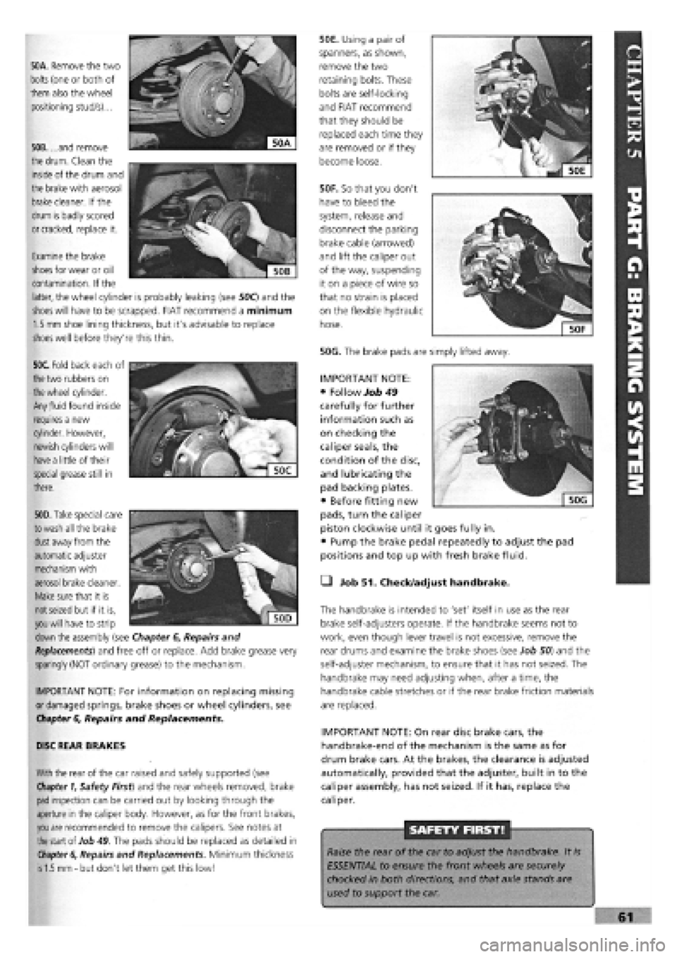
50A. Remove the two
bolts
(one or both of
them also the wheel
positioning stud/s)...
50B. ...and remove
the
drum.
Clean the
inside of the drum and
the brake with aerosol
brake
cleaner. If the
drum is badly scored
or cracked,
replace it.
50F. So that you don't
have to bleed the
system, release and
disconnect the parking
brake cable (arrowed)
and lift the caliper out
of the way, suspending
it on a piece of wire so
that no strain is placed
on the flexible hydraulic
hose.
50G. The brake pads are simply lifted away.
50E. Using a pair of
spanners, as shown,
remove the two
retaining bolts. These
bolts are self-locking
and FIAT recommend
that they should be
replaced each time they
are removed or if they
become loose.
Examine the brake
shoes
for wear or oil
contamination. If the
latter, the wheel cylinder is probably leaking (see 50C) and the
shoes will
have to be scrapped. FIAT recommend a minimum
1.5 mm
shoe lining thickness, but it's advisable to replace
shoes
well before they're this thin.
50C. Fold back each of
the
two rubbers on
the wheel
cylinder.
Any
fluid
found inside
requires a new
cylinder. However,
newish cylinders will
have a
little of their
special grease still in
there.
. """
€
Sjjj
KV,1
| 50D|
50D. Take
special care
to wash
all the brake
dust
away from the
automatic adjuster
mechanism with
aerosol brake cleaner.
Make
sure that it is
not seized
but if it is,
you will
have to strip
down
the assembly (see Chapter
6,
Repairs and
Replacements)
and free off or replace. Add brake grease very
sparingly (NOT ordinary grease) to the mechanism.
IMPORTANT NOTE: For information on replacing missing
or damaged springs, brake shoes or wheel cylinders, see
Chapter
6,
Repairs and Replacements.
DISC REAR BRAKES
With
the rear of the car raised and safely supported (see
Chapter 1,
Safety First) and the rear wheels removed, brake
pad
inspection can be carried out by looking through the
aperture in the caliper body. However, as for the front brakes,
you are
recommended to remove the calipers. See notes at
the
start of Job
49.
The pads should be replaced as detailed in
Chapter 6,
Repairs and Replacements. Minimum thickness
is 1.5 mm -
but don't let them get this low!
• Job 51. Check/adjust handbrake.
The handbrake is intended to 'set' itself in use as the rear
brake self-adjusters operate. If the handbrake seems not to
work, even though lever travel is not excessive, remove the
rear drums and examine the brake shoes (see Job 50) and the
self-adjuster mechanism, to ensure that it has not seized. The
handbrake may need adjusting when, after a time, the
handbrake cable stretches or if the rear brake friction materials
are replaced.
IMPORTANT NOTE: On rear disc brake cars, the
handbrake-end of the mechanism is the same as for
drum brake cars. At the brakes, the clearance is adjusted
automatically, provided that the adjuster, built in to the
caliper assembly, has not seized. If it has, replace the
caliper.
SAFETY FIRST!
Raise the rear of the car to adjust the handbrake. It
is
ESSENTIAL to ensure the front wheels are securely
chocked in both directions, and that axle stands are
used to support the car.
IMPORTANT NOTE:
• Follow Job 49
carefully for further
information such as
on checking the
caliper seals, the
condition of the disc,
and lubricating the
pad backing plates.
• Before fitting new
pads, turn the caliper
piston clockwise until it goes fully in.
• Pump the brake pedal repeatedly to adjust the pad
positions and top up with fresh brake fluid.
Page 124 of 171

Job 2. Steering wheel - removal
and refitting.
1 - coil spring 2 - trailing arm 3 - rubber bump stops 4 - handbrake cable 5 - axle beam
6 - anti-roll bar 7 - rear brake regulator 8 - shock absorber 9 - trailing arm hinge bolt
Job 1-1C
SAFETY FIRST!
• AIR BAGS. Because of the safety hazards, both
mechanical and chemical (the air bag contains an
explosive device)
-
we strongly recommend that a car
with an air bag fitted to its steering wheel should be
taken to a FIAT dealer to have its steering wheel
removed and refitted under controlled conditions.
STEERING WHEELS WITHOUT AIR BAGS ONLY
Q Point 1C: The rear suspension design shown here is
common to both Tipo and Tempra.
1 - beam axle 2 - rubber buffer pads 3 - shock absorber top bolt 4 - coil spring 5 - shock absorber 6 - bottom nut and bolt securing shock absorber to trailing arm 7 - trailing arm 8 - anti-roll bar 9 - nut and bolt securing trailing arm to beam axle 10 - stub axle/hub nut 11 - wheel hub 12 - stub axle 13
-
hub cap
Job 1-1D
Q Point 1D: This exploded drawing of the rear suspension
gives a clear view of how several of the assemblies are fitted.
• Step 3: Slacken the lock nut
(arrowed) on the track rod by just enough
to free the balljoint, but no
more.
• Step 4: Now undo the
balljoint to steering arm nut
until the bottom of the nut is
level with the end of the thread.
Job
3-3
Job 3. Track rod end balljoint -
replacement.
Q Step 1: Slacken the roadwheel nuts
on the side to be worked.
Q Step 2: Jack up and support the car
on axle stands and remove the road
wheel.
• Step 1: Undo the wheel
cover fixing bolts (positions
arrowed) from underneath.
• Step 2: Using a ring
spanner or socket and
supporting the wheel with the
other hand (see illustration
Job
2-1),
undo the centre
fixing nut and remove the
steering wheel.
H INSIDE INFORMATION!
Never use the steering column lock to stop the wheel
turning when removing and refitting the centre nut-this
could cause damage and would be a costly mistake. H
• Step 3: Refit in reverse order, tightening the fixing nut to
its specified torque. See Chapter
3,
Facts and Figures.
Page 130 of 171

• Step 8:
Support the
axle beam with
the jack and
undo the
mounting bolts
(arrowed and
indicated by
operator with
socket bar).
Lower the
complete unit
from the car.
IMPORTANT NOTE: In this shot, the top shock absorber
mountings have been disconnected, leaving the shock
absorber fitted to the suspension and the coil springs in
place. We recommend 'our' approach, covered in Step 7!
• Step 9: Undo the bolts securing the anti-roll bar and
remove it. (See Job 9.) Disconnect the brake pipes from the
side to be worked on and remove the brake drum.
Q Step 10: Remove the hub cap (see illustration Job 1-1D,
part 13) by carefully tapping and levering with a screwdriver.
• Step 11: Undo the hub nut (see illustration Job 1-1D,
part
10).
PART H: BRAKES
• Step 12: A special tool
(1857508000) or a VERY
strong Allen key (a) will be
required to reach into the
hub (b), and plenty of
leverage!
Q Step 13: Remove the
hub and inspect the bearing
for roughness or noise or
roughness when turning it by hand.
E3 INSIDE INFORMATION! The bearing is lubricated for
life and is only supplied as an assembly with the hub. B
• Step 14: Inspect the stub axle pin (see illustration Job
1-
1D, part
12)
for any signs of damage or distortion. Replace if
in doubt.
Q Step 15: Refitting is the reverse of removal but note the
following:
• See Chapter
3,
Facts and Figures for all tightening
torques as you progress through the assembling.
• Use new hub nuts and fully tighten once the suspension is
mounted to give you stability.
• Refer to PART H: BRAKES when refitting the brake parts
and bleeding the brakes.
PART H: Contents %
Job 1. Understanding Tipo/Tempra brakes.
Job 2. Front brake pads
-
replacement.
Job 3. Front brake caliper
-
replacement.
Job 4. Front brake disc
-
replacement.
Job 5. Rear brake shoes
-
replacement.
Job 6. Rear wheel cylinder
-
replacement.
Job 7. Rear brake disc pads
-
replacement.
Job 8. Rear brake caliper
-
replacement.
Job 9. Rear brake disc
-
replacement.
Job 10. Master cylinder
-
replacement.
Job 11. Servo check
-
remove and refit.
Job 12. Pressure regulating valve, non-ABS system -
replacement and adjustment.
Job 13. Pressure regulating valves, ABS system
-
replacement
and adjustment.
Job 14. RPM sensors, ABS systems
-
replacement.
Job 15. Flexible hoses
-
replacement.
Job 16. Metal pipes
-
replacement.
Job 17. Brake bleeding.
Job 18. Handbrake cables
-
replacement.
Job 1. Understanding
Tipo/Tempra brakes.
• Point
1
A: This is the standard disc/drum system used on
cars without anti-lock brakes, shown here in left hand drive
form.
1 - fluid reservoir and master cylinder 2 - servo 3
-
front disc brakes
4 - handbrake lever 5 - rear drum brakes 6
-
four way pipe union 7 - load proportioning/ pressure limiting valve
Job 1-1A
1 - front disc brakes 2
-
front flywheel 3 - front wheel RPM sensors 4 - hydraulic control unit 5 - brake light switch 6 - device failure warning light switch
7 - rear flywheel 8 - main control relay with excess voltage protection 9 - electronic control unit 10 - rear disc brakes 11 - rear wheel RPM sensors 12 - load proportioning/pressure limiting valve Job
1-1B
Page 131 of 171

Q Point 1B: This version shows the anti-lock braking system
and has discs replacing drums at the rear. One of two makes
is used
-
Lucas or Bosch
-
and both are similar in design.
Shown here is the Bosch ABS system in left hand drive form.
Apart from checking that the hydraulic and electrical connec-
tions are sound, anti-lock brakes are not repairable. Individual
components and friction materials can be replaced but
otherwise, you should consult your FIAT dealer for diagnosis
of system faults (with specialised equipment) and rectification.
SPECIAL NOTES: • Unplug the electronic control unit
(ECU) before any electric welding is carried out.
• When oven drying paint, the ECU cannot withstand 95
degrees Celsius for more than a few minutes or 85
degrees Celsius for more than 2 hours.
• Disconnect the battery earth before removing the
hydraulic control.
• When reconnecting the battery, make sure the connec-
tions are firm and sound.
Q INSIDE INFORMATION: When disconnecting brake
pipes or hoses, it is essential to minimise brake fluid loss.
This can be done by unscrewing the master cylinder
reservoir cap, laying a sheet of plastic across the opening,
and refitting the cap. This will prevent atmospheric
pressure from pushing the fluid out of opened lines. D
Job 2. Front brake pads -
replacement.
Changing and checking the Tipo's and Tempra's brake pads
are virtually identical jobs. See Chapter 5, Servicing Your
Car, pages 59 and 60
Job 3. Front brake caliper -
replacement.
Carry out this work with reference to Chapter 5, Servicing
Your Car, Job 49, pages 59 and 60.
Q Step 1: Slacken the front road wheels, jack up the car
and support on axle stands. Remove the wheels.
Q Step 2: Unplug
the brake pad wear
sensor (a
-
arrowed)
and ease the fluid
pipe/hose from the
bracket (b
-
arrowed)
on
the shock absorber
leg.
Q Step 3: Undo the brake fluid pipe union from the caliper
body and plug the end to prevent too much fluid loss.
Q Step 4: Undo the bolts and remove the caliper.
D INSIDE INFORMATION! The caliper securing bolts must
always be replace by new FIAT ones when loosened or
removed. They are of a special self-locking type. B
Q Step 5: Refit in reverse order and bleed the brakes, see
Job 17
Job 4. Front brake disc -
replacement.
Q Step 1: Carry out Steps 1 to 4 in Job 3.
• Step 2:
Undo the
securing bolts
and remove
the caliper
support
bracket.
• Step 3:
Undo the disc
fixing bolts
and withdraw
the brake
disc.
Q Step 4: Refit the remaining parts in reverse order of
removal. See Chapter 5, Servicing Your Car.
Carry out this work with reference to Chapter 5, Servicing
Your Car, Job 50, pages 60 and 61.
Job 5. Rear brake shoes -
replacement.
H INSIDE INFORMATION! It often helps to work on one
side at a time, completing all the work on that side of
the car and using the other side as a reference before
you start dismantling it. Q
• Before refitting the disc,
ensure that the mating
surfaces
-
hub to disc, are
clean and undamaged.
• Spin the disc to be sure there is no 'run out' before
proceeding further.
Job 4-2
Page 133 of 171
Job 8. Rear brake caliper -
replacement.
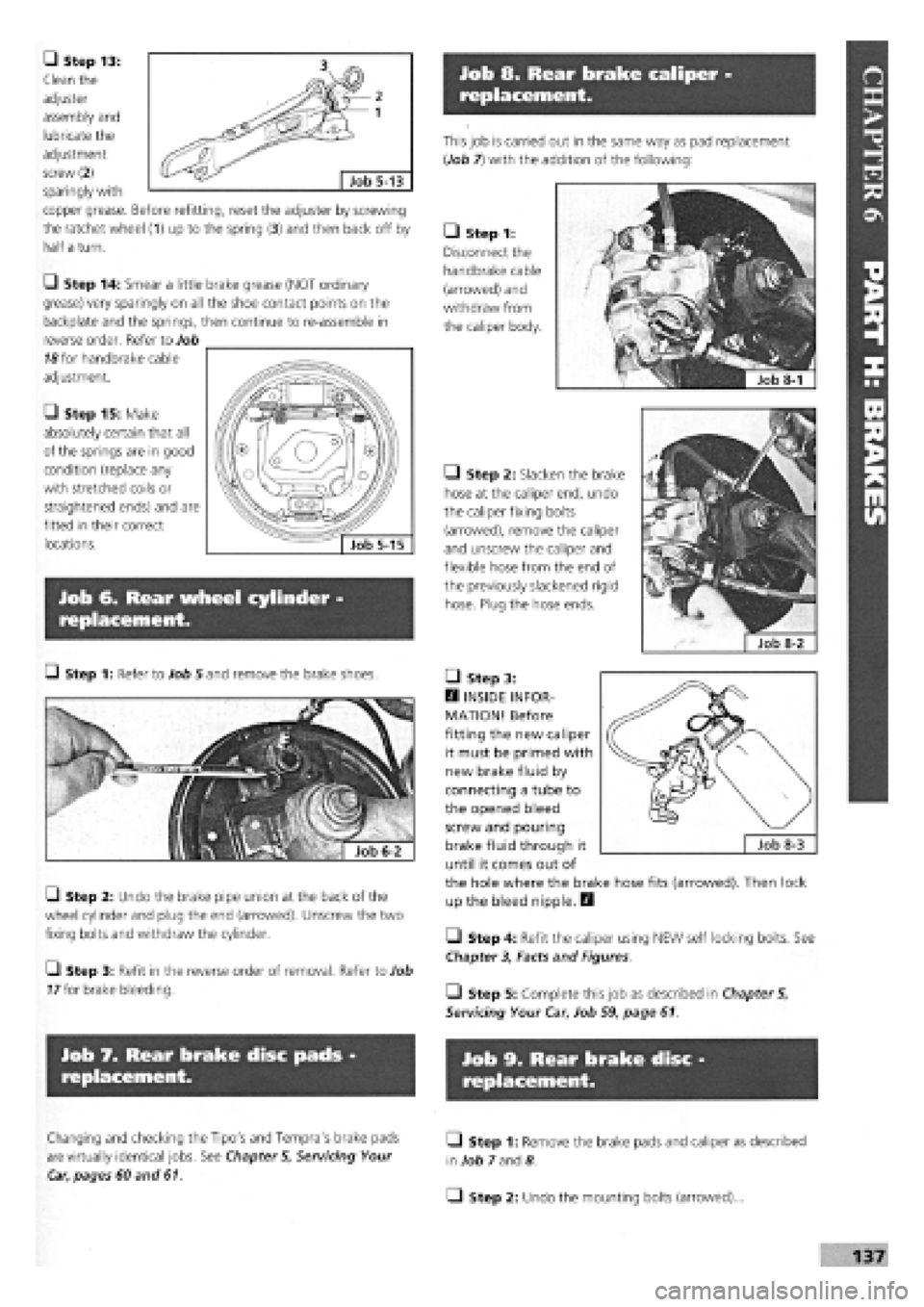
• Step 13:
Clean the
adjuster
assembly and
lubricate the
adjustment
screw (2) _ ^ Job 5_13
sparingly with
copper grease. Before refitting, reset the adjuster by screwing
the ratchet wheel (1) up to the spring (3) and then back off by
half a turn.
This job is carried out in the same way as pad replacement
{Job 7) with the addition of the following:
• Step 1:
Disconnect the
handbrake cable
(arrowed) and
withdraw from
the caliper body.
• Step 2: Slacken the brake
hose at the caliper end, undo
the caliper fixing bolts
(arrowed), remove the caliper
and unscrew the caliper and
flexible hose from the end of
the previously slackened rigid
hose. Plug the hose ends.
• Step 14: Smear a little brake grease (NOT ordinary
grease) very sparingly on all the shoe contact points on the
backplate and the springs, then continue to re-assemble in
reverse order. Refer to Job
18
for handbrake cable
adjustment.
• Step 15: Make
absolutely certain that all
of the springs are in good
condition (replace any
with stretched coils or
straightened ends) and are
fitted in their correct
locations.
Job 6. Rear wheel cylinder -
replacement.
Q Step 1: Refer to Job 5 and remove the brake shoes.
Q Step 2: Undo the brake pipe union at the back of the
wheel cylinder and plug the end (arrowed). Unscrew the two
fixing bolts and withdraw the cylinder.
Q Step 3: Refit in the reverse order of removal. Refer to Job
77
for brake bleeding.
• Step 3:
H INSIDE INFOR-
MATION! Before
fitting the new caliper
it must be primed with
new brake fluid by
connecting a tube to
the opened bleed
screw and pouring
brake fluid through it
until it comes out of
the hole where the brake hose fits (arrowed). Then lock
up the bleed nipple. Q
Q Step 4: Refit the caliper using NEW self locking bolts. See
Chapter 3, Facts and Figures
• Step 5: Complete this job as described in Chapter 5,
Servicing Your Car, Job 59, page 61.
Job 7. Rear brake disc pads
replacement.
Job 9. Rear brake disc
replacement.
Changing and checking the Tipo's and Tempra's brake pads
are virtually identical jobs. See Chapter 5, Servicing Your
Car, pages 60 and 61.
Q Step 1: Remove the brake pads and caliper as described
in
Job 7
and
8
• Step 2: Undo the mounting bolts (arrowed)...