1988 FIAT TEMPRA radio
[x] Cancel search: radioPage 3 of 171

Mains Electricity
Avoid the use of mains electricity when working on the vehicle,
whenever possible. Use rechargeable tools and a DC inspection
lamp, powered from a remote 12V battery
-
both are much
safer. However, if you do use mains-powered equipment,
ensure that the appliance is wired correctly to its plug, that
where necessary it is properly earthed (grounded), and that the
fuse is of the correct rating for the appliance. Do not use any
mains powered equipment in damp conditions or in the vicinity
of fuel, fuel vapour or the vehicle battery.
Always use an RCD (Residual Current Device) circuit breaker
with mains electricity. Then, if there is a short, the RCD circuit
breaker minimises the risk of electrocution by instantly cutting
the power supply.
Ignition System
Never work on the ignition system with the ignition switched
on, or with the engine being turned over on the starter, or
running and you are recommended never to do so.
Touching certain parts of the ignition system, such as the HT
leads, distributor cap, ignition coil etc., can result in a severe
electric shock or physical injury as a hand is pulled sharply away.
Voltages produced by electronic ignition systems are much
higher than those produced by conventional systems and could
prove fatal, particularly to people with cardiac pacemaker
implants. Consult your handbook or main dealer if in any
doubt.
Cooling Fan
On many vehicles, the electric cooling fan can switch itself on
even with the ignition turned off. This is especially likely after
driving the car and parking it before turning off, after which
heat rises to the top of the engine and turns the fan on,
suddenly and without warning. If you intend working in the
engine bay, it's best to do so when the engine is cold, to
disconnect the battery, or keep away from the fan, if neither of
these are possible.
Battery
Never cause a spark, smoke, or allow a naked light near the
vehicle's battery, even in a well ventilated area. Highly explosive
hydrogen gas is given off as part of the charging process.
Battery terminals on the car should be shielded, since a spark
can be caused by any metal object which touches the battery's
terminals or connecting straps.
IMPORTANT NOTE: Before disconnecting the battery earth
(ground) terminal read the relevant FACT FILE in Chapter 5
regarding saving computer and radio settings.)
When using a battery charger, switch off the power supply
before the battery charger leads are connected or disconnected.
If the battery is not of the 'sealed-for-life' type, loosen the filler
plugs or remove the cover before charging. For best results the
battery should be given a low rate trickle charge overnight. Do
not charge at an excessive rate or the battery may burst.
Always wear gloves and goggles when carrying or when
topping up the battery. Acid electrolyte is extremely corrosive
and must not be allowed to contact the eyes, skin or clothes.
Brakes and Asbestos
Obviously, a car's brakes are among its most important safety
related items. ONLY work on your vehicle's braking system if
you are trained and competent to do so. If you have not been
trained in this work, but wish to carry out the jobs described in
this book, we strongly recommend that you have a garage or
qualified mechanic check your work before using the car.
Whenever you work on the braking system components, or
remove front or rear brake pads or shoes: i) wear an efficient
particle mask; ii) wipe off all brake dust from the brakes after
spraying on a proprietary brand of brake cleaner (never blow
dust off with compressed air); iii) dispose of brake dust and
discarded shoes or pads in a sealed plastic bag; iv) wash your
hands thoroughly after you have finished working on the
brakes and certainly before you eat or smoke; v) replace shoes
and pads only with asbestos-free shoes or pads. Note that
asbestos brake dust can cause cancer if inhaled; vi) always
replace brake pads and/or shoes in complete 'axle' sets of four
-
never replace the pads/shoes on one wheel only.
Brake Fluid
Brake fluid absorbs moisture rapidly from the air and can
become dangerous resulting in brake failure. You should
change the fluid in accordance with your vehicle manufacturer's
recommendations or as advised in this book. Never store (or
use) an opened container of brake fluid. Dispose of the
remainder at your Local Authority Waste Disposal Site, in the
designated disposal unit, not with general waste or with waste
oil.
Engine Oils
Always wear disposable plastic or rubber gloves when draining
the oil from your engine, i) Note that the drain plug and the oil
are often hotter than you expect. Wear gloves if the plug is too
hot to touch and keep your hand to one side so that you are
not scalded by the spurt of oil as the plug comes away; ii) There
are very real health hazards associated with used engine oil. In
the words of one manufacturer's handbook "Prolonged and
repeated contact may cause serious skin disorders, including
dermatitis and cancer." Use a barrier cream on your hands and
try not to get oil on them. Always wear gloves and wash your
hands with hand cleaner soon after carrying out the work. Keep
oil out of the reach of children; iii) NEVER, EVER dispose of old
engine oil into the ground or down a drain. In the UK, and in
most EC countries, every local authority must provide a safe
means of oil disposal. In the UK, try your local Environmental
Health Department for advice on waste disposal facilities.
Plastic Materials
Many of the materials used (polymers, resins, adhesives and
materials acting as catalysts and accelerators) contain dangers in
the form of poisonous fumes, skin irritants, and the risk of fire
Page 32 of 171

(ignition-ON) position and press down the button between the
two terminals on the reservoir cap
-
when fitted. The warning
light on the dash should light up. When no button is fitted,
unscrew and raise the cap (ignition key ON) to check the
warning light. Check the bulb, check the fuse, or have your
FIAT dealer repair the warning system, if faulty.
• Job 4. Battery
-
check electrolyte level.
FACT FILE: DISCONNECTING THE
BATTERY
• Many vehicles depend on a constant
power supply from the battery; with
these you find yourself in trouble if you
simply disconnect the battery. You
might find the car alarm goes off, or that the engine
management system forgets all it ever 'learned', making
the car feel odd to drive until it has re-programmed
itself. You might also find that the radio refuses to
operate until its correct security code is keyed into it.
• On cars with engine management systems and/or
coded radios, you must ensure the car has a constant
electrical supply, even with the battery removed. You
will need a separate 12 volt battery; put a self-tapping
screw into the positive lead near the battery terminal
before disconnecting it, and put a positive connection
to your other battery via this screw.
• Be EXTREMELY CAREFUL to wrap insulation tape
around the connection so that no short is caused. The
negative terminal on the other battery must be
connected to the car's bodywork.
SAFETY FIRST!
• The gas given off by a battery is highly explosive.
Never smoke, use a naked flame or allow a spark in
the battery compartment.
• Never disconnect the battery (it can cause sparking)
with the battery caps removed.
• All vehicle batteries contain sulphuric acid. If the
acid comes into contact with the skin or eyes, wash
immediately with copious amounts of cold water and
seek medjcal advice.
• Do not check the battery levels within half an hour
of the battery being charged with a separate battery
charger because the addition of fresh water could
cause electrolyte to flood out.
4. Check the electrolyte
level in the battery. MAX
and MIN lines (arrowed)
are moulded into the
translucent battery
casing. In the case of
non-FIAT-supplied
batteries, the cell caps or
strip (a) may need to be
removed to see the level.
Original FIAT batteries are of the 'maintenance-free' type and
usually do not need topping-up. However, if necessary, top up
after prising off the cell sealing strip with a screwdriver. Top-
up each cell ONLY with distilled or de-ionised water.
• Job 5. Screen/headlight washer fluid
check level.
5A. Top up with a mixture of
water and screen-wash
additive, mixed according to
the instructions on the
container. FIAT recommend
Arexons DP1. The reservoir
for front screen, rear screen
and headlights (as appro-
priate) is situated in the engine
bay: adjacent to the left-hand
strut, behind the battery...
5B. ...and behind the
coolant expansion
tank on diesel
models, as illustrated
here.
• Job 6. Tyres
-
check pressures and condition
(road wheels).
/
6A. Check the tyre
pressures using a
reliable and accurate
gauge. Note that the
recommended
pressures (see
Chapter
3,
Facts and
Figures) are given for ^^
iH^KKSEI ^ "'
COLD tyres. Tyres
warm up as the car is used
-
and warm tyres give a false (high)
reading. You should also check for wear or damage at the
same time.
SAFETY FIRST!
• If a tyre is worn more on one side than another,
consult your FIAT dealer or a tyre specialist. It probably
means the tracking needs re-setting, though it could
indicate suspension damage, so have it checked.
• If a tyre is worn more in the centre or on the edges,
this indicates incorrect tyre pressures.
• Incorrectly inflated tyres wear rapidly, can give
dangerous handling, and can worsen fuel
consumption.
Every three months,
raise each wheel off
the ground and turn it
slowly between your
36
6B. Every few weeks, examine the tyre treads for wear using a
tread-depth gauge. This will help you keep safe and on the
right side of the law!
Check treads visually
every time you check
the pressures.
Page 106 of 171

PART E: ELECTRICAL ARID INSTRUMENTS
PART E: Contents
Job 1. Alternator
-
removal and refitting. Job 10. Rear light cluster
-
replacement.
Job 2. Starter motor
-
removal and refitting. Job 11. Side repeater indicators
-
replacement.
Job 3. Instrument panel
-
removal and refitting. Job 12. Number plate light
-
replacement.
Job 4. Speedometer cable
-
replacement. Job 13. Interior/courtesy light
-
removal and refitting.
Job 5. Windscreen wiper motor
-
replacement. Job 14. Fuel gauge sender unit
-
removal and refitting.
Job 6. Hatchback wiper motor
-
replacement. Job 15. Central locking
-
replacement of components.
Job 7. Windscreen washer pump
-
replacement. Job 16. Electric windows
-
replacement of components.
Job 8. Radio aerial
-
replacement. Job 17. Diesel engines. Glow plugs
-
checking and
Job 9. Headlight cluster
-
replacement. replacement.
Job 1. Alternator - removal
and refitting.
Job 3. Instrument panel -
removal and refitting.
• Step 1: Disconnect the battery earth lead.
Q Step 2: Disconnect all the wires from the back of the
alternator
-
the main output wire is released by undoing its
securing nut. Slacken the bolt securing the inboard end of the
adjustment bar, undo and remove the bolt from the alternator
end of the bar. Slacken the drivebelt and remove it.
Q Step 3: On manual steering cars, unbolt and remove the
adjuster bracket from the cylinder block.
Q Step 4: Release the securing buttons and remove the
engine splash shield on power steering cars.
Q Step 5: Undo the nut from the long through bolt and
note the position of the washers. Support the alternator and
remove the bolt, then withdraw the alternator from the car.
Q Step 6: Refit in reverse order and make sure your
electrical connections are sound. Adjust the drivebelt tension.
See Chapter 5, Servicing Your Car
• Step 1: Disconnect
terminal.
• Step 2: Undo the
screws (arrowed) and
remove the speaker
cover (1).
Job 2. Starter motor - removal
and refitting.
• Step 1: Disconnect the battery earth lead.
• Step 2:
Undo and remove
all the electrical
connections (a)
from the starter
(b) and starter
solenoid (c).
Q Step 4: Refit in reverse order, ensuring that all connec-
tions are sound.
Q Step 5: Raise the instrument panel enough to unplug
the connectors from the rear. Disconnect the speedometer
drive (if non-electronic type) and remove the instrument
panel from the car.
Q Step 6: Refit in the reverse order and be sure that all
connections are properly made.
Job 4. Speedometer cable
replacement.
• Step 1: H INSIDE INFORMATION! The cable comes in
two parts, joined in the middle by a connector (a). Q
• Step 2: Follow Job 3, Steps 1 to 3 Then, lift the
instrument panel
sufficiently so that
you can gain
access to the
cable.
^Jj
Job
4-1
the battery at the negative (earth)
• Step 3: Undo the
exposed screws that
secure the
instrument panel
(arrowed).
• Step 4: Slide
off the screw
cover
(2)
from
the other end of
the instrument
panel and
remove the two
screws found beneath it.
• Step 3:
Undo the three mounting bolts and the wiring harness bracket
from the top bolt and withdraw the starter.
Page 108 of 171
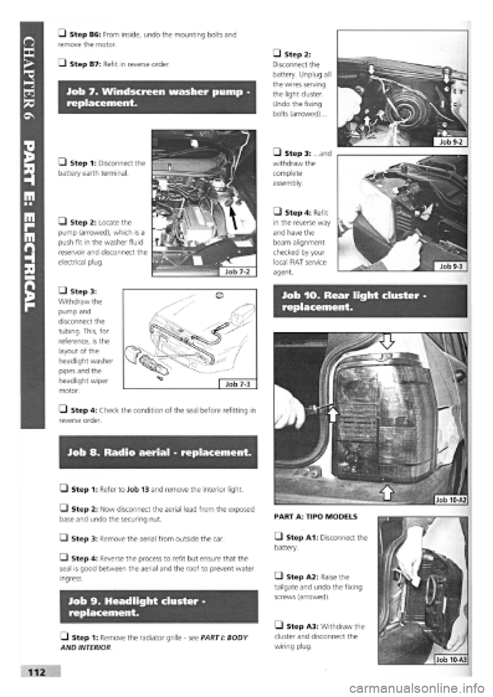
Job
9-2
Job 7. Windscreen washer pump -
replacement.
Job 10. Rear light cluster
replacement.
Job 8. Radio aerial - replacement.
• Step 1: Refer to Job 13 and remove the interior light.
Q Step 2: Now disconnect the aerial lead from the exposed
base and undo the securing nut.
• Step 3: Remove the aerial from outside the car.
Q Step 4: Reverse the process to refit but ensure that the
seal is good between the aerial and the roof to prevent water
ingress.
Job 9. Headlight cluster -
replacement.
• Step 1: Remove the radiator grille
-
see PARTI: BODY
AND INTERIOR
PART A: TIPO MODELS
O Step A1: Disconnect the
battery.
• Step A2: Raise the
tailgate and undo the fixing
screws (arrowed).
• Step A3: Withdraw the
cluster and disconnect the
wiring plug.
• Step 2:
Disconnect the
battery. Unplug all
the wires serving
the light cluster.
Undo the fixing
bolts (arrowed)...
• Step 3: ...and
withdraw the
complete
assembly.
Q Step B6: From inside, undo the mounting bolts and
remove the motor.
Q Step B7: Refit in reverse order.
O Step 1: Disconnect the
battery earth terminal.
• Step 2: Locate the
pump (arrowed), which is a
push fit in the washer fluid
reservoir and disconnect the
electrical plug.
• Step 4: Refit
in the reverse way
and have the
beam alignment
checked by your
local FIAT service
agent.
• Step 3:
Withdraw the
pump and
disconnect the
tubing. This, for
reference, is the
layout of the
headlight washer
pipes and the
headlight wiper
motor.
• Step 4: Check the condition of the seal before refitting in
reverse order.
Page 151 of 171

IMPORTANT NOTE: Not all of the components listed here are fitted to all models.
CHAPTER 7
WIRING DIAGRAMS
IMPORTANT NOTE: Not all of the components listed here
are fitted to all models.
IMPORTANT NOTES:
3. We have sometimes shown the wiring diagram for a
'highest' spec, model, in the knowledge that 'lower'
spec, models are usually similar with the deletion of
certain components.
1. There are several hundred FIAT wiring diagrams for
the whole TIPO range. This is a representative selection,
covering the majority of applications. However, in the
event that your car's details are not covered here,
consult your nearest FIAT dealer.
2 All of the following are Tipo wiring diagrams. Tempra
saloons and estates are essentially similar.
4. 'EEC Stage 2 Engines' In late 1994, Tipo 1.4 and 2 -
Litre and Tempra 1.6 MPI vehicles were modified to suit
new emission regulations. These changes were NOT only
engine-related. Vehicles covered by this manual are Tipo
1.4 (with engine code no. 836A4.000) and Tempra 1.6
(with engine code 159B9.000). See Page 27 for location
of codes.
KEY:
1 Left front light cluster 2 Reversing light switch 3a Left horn 4 Electric cooling fan 5 Dual contact coolant thermal switch 6 Right longitudinal cable connection 7 Right front earth 8 Right front light cluster 9 Right horn 10 Screen/rear window washer pump 11 Left brake pad wear sensor 11A Right brake pad wear sensor 12 Ignition coil 12A Ignition coil with power module 12B Ignition coil with H.T. points 13 Digiplex electronic ignition control unit 13A Digiplex electronic ignition lead connection 13C Diagnostic socket for Digiplex electronic ignition 14 Left front earth 15 Battery earth 16 Engine coolant temperature sender unit 17 Battery 18 Ignition distributor 19 Sparkplug 20 Spark plug 21 Sparkplug 22 Spark plug 23 TDC sensor 24 Alternator 25 Oil pressure switch 26 Connector block 27 Brake fluid level sensor 28 Left side turn signal 30 Idle cut-out device 31 Starter motor 32 Throttle valve sensor 33 Pulse generator for speedometer signal 34 Windscreen wiper 35 Right side turn signal 36 P.T.C. resistor for heating fuel duct 37 Thermal switch for PTC 38 Vacuum sensor for vacuum gauge 39 Fuse and relay control unit E2 Turn signal and hazard warning light flasher E4 Fog light relay E5 Horn relay E6 Heated back window relay E7 Switch discharge connector E9 Windscreen wiper intermittent function E10 Rear fog light relay E11 Dipped beam relay E12 Main beam relay E13 Side light control relay E14 Central locking electronic control unit E1-E3-E8-E15-available (unused)
40 PTC resistor activation relay 41 20A fuse for inlet duct heater circuit 42 25A fuse for electric window ECU 43 Junction between facia cable and heater cable 44 Earth on left hand side of facia 45 Junction between facia cable and left front door
G Horn button H Windscreen wiper stalk I Back window wash/wipe selector L Heated rear windscreen switch M Rear screen wash/wipe switch N Windscreen wiper speed switch cables 56 Junction: facia cable and r.h. rear door cables Electric window control unit 57 Glove compartment light bulb Provision for left front speaker 58 Facia cable coupling with right front door cables Provision for left rear speaker 59 Facia cable coupling with right front door cables Supplementary earth point 60 Provision for right front speaker Instrument panel 60A Provision for right rear speaker A Direction indicators warning light 61 L.h. button for courtesy light and electric window B Side lights warning light 62 Junction between rear cable and left rear door C Main beam headlights warning light cables D Heated rear windscreen warning light 63 Junction between rear cable and left front door E Rear fog lights warning light cables E1 Fog lights warning light 64 Left front door lock motor and left front door F Hazard warning lights warning light open warning light G Battery recharging warning light 65 Left front electric window motor H Insufficient engine oil pressure warning light 66 Electric front window control buttons I Trip counter 67 Cigar lighter J Left brake lining wear warning light 68 Braking light switch J1 Seat belt undone warning light 69 Passenger compartment courtesy light K Handbrake on and low brake fluid level 69A Passenger compartment courtesy light with door warning light lock remote control receiver L Choke warning light 70 Hand brake warning light switch M ABS failure warning light 71 Passenger compartment ventilation fan switch N Instrument panel light bulbs 71A Passenger compartment ventilation control 0 Fuel level gauge 72 Passenger compartment ventilation fan speed P Coolant temperature gauge regulation resistor P1 Engine oil pressure gauge 73 Passenger compartment ventilation fan P2 Engine oil temperature gauge 74 Heater controls light bulbs Q Clock 75 Right front door lock motor and right front door R Heater plugs warning light open warning light S Speedometer 76 Right front electric window motor S1 Speed warning light 77 Right front electric window control button T Rev counter 78 R.h. button for courtesy lights and window U Trailer turn signal warning light 79 Luggage compartment lighting X Water in fuel filter warning light 80 Left rear earth Y Excessive turbocharging air pressure warning 80A Right rear earth light 81 Rear cable connection Y1 Lambda probe failure warning light 82 Left tail-light cluster Z Excessive automatic transmission fluid 83 Left rear door lock motor temperature warning light 84 Fuel level gauge Z1 Injection system failure warning light 85 Tailgate lock/release motor Ignition switch 86 Left number plate light Available for radio 87 Right number plate light Available for radio 88 Rear window wiper motor Hazard warning lights switch 89 Heated rear windscreen Stalk unit 90 Right tail-light cluster A Rear fog lights switch 91 Right rear door lock motor B Exterior lighting selector 92 Glow plug preheating system ECU c Control lighting bulb 93 Glow plugs D Light flasher button 94 Engine cooling fan first speed additional resistor E Turn signal stalk 95 30A fuse for engine cooling fan F Dipped/main beam headlight selector 96 Switch for automatic advance
155
Page 162 of 171

Diagram 13: Models: DGT1100
-
1400 and 1600
-
Engine Radiator Cooling
-
Car Interior Ventilation
-
Available for Radio -
Cigar Lighter
-
Courtesy Light
Diagram 14: Model: 1697 Diesel ('93 Range) Super
-
Engine Cooling System
-
Car Interior Ventilation
-
Provision for Car
Radio
-
Cigar Lighter
-
Courtesy Light
NB
-
Early/non-Super models similar, but no items 47A, 295, and 60A. Item 95 has 40A fuse on DGT Models
Page 163 of 171

Diagram 15: Model: 1930 Turbo Diesel DGT
-
Engine Radiator Cooling
-
Car Interior Ventilation
-
Available for Radio -
Cigar Lighter
-
Courtesy Light