Page 33 of 171

• Whenever a light fails to
work, check its fuse before
replacing the bulb.
• A blown bulb often causes a fuse to 'go' in
sympathy.
hands, looking and feeling for any bulges, tears or splits in the
tyre walls, especially the inner sidewalls. (See Job 59 for spare
tyre checks.)
H INSIDE INFORMATION: In time, rubber deteriorates,
increasing the risk of a blow-out. Keep your eye on the
sidewalls of older tyres. If you see any cracking, splits or
other damage scrap the tyre. If you're not sure, consult
your FIAT dealer or tyre specialist. Q
_) Job 7. Check lights/change bulbs.
7A. Pull off the
headlight multi-
plug (A) and peel
the rubber cover
(B) from the back
of the headlight.
7B. Unhook the
bulb securing
spring (C) from the
retention clip by
squeezing inwards
(arrowed) and
withdraw the bulb
(D).
Without touching the bulb glass, fit the new bulb. A locating
tag ensures it only goes in in the correct position. Refit and
reconnect in the reverse order.
HEADLIGHTS
IMPORTANT NOTE: On Diesel models with the air filter
mounted behind the right-hand headlight unit, you will
first have to remove the large hose, unscrew the clamp
nut and take off the air filter assembly. See Job 31. On
later models, there is sometimes an air intake silencer in
the same place.
7F. Slide the unit towards the front of the car, then pull out
from the panel. Turn the bulbholder (A) anti-clockwise,
remove it, and pull out the press-fit 12V/5W bulb.
INDICATOR SIDE REPEATERS
-
ROUND TYPE
holder is pushed in slightly, turned anti-clockwise and
removed. The bulb (B) is a push-fit within it.
FRONT DIRECTION INDICATORS
-
TURBO DIESEL
MODELS
7D. Remove the
lens (B) by
inserting a screw-
driver as shown
and pressing down
the tab (A). You
can easily remove
the bulbs with the
lens removed.
FRONT DIRECTION INDICATORS
-
ALL OTHER
MODELS
7E. From inside the
engine bay, turn
the bulbholder
slightly, anti-
clockwise, and pull
out. Remove the
bulb (B) and press
in a new one. Push
in and twist
clockwise.
INDICATOR SIDE REPEATERS
-
RECTANGULAR TYPE
CAS / * touc^ a halogen
• headlight (or driving light)
bulb with bare fingers you
will
shorten its life, so handle with a piece of
tissue
paper. If the bulb is touched, wipe it carefully with
methylated spirit.
FRONT SIDE
LIGHTS
7C.
The side light
bulb holder is
under the main
headlight bulb.
The bayonet-type
7G. Twist the lens (A) anti-clockwise and remove it. The push-
in bulb can be pulled out and replaced.
Page 34 of 171

ruvj
uivjh I
uuluj
^ Use a magnetic screw-
driver or place some thick
grease on the end of the
screwdriver to prevent the screws from falling
-
especially when replacing the lens.
7H. Undo screws (A) and (B), pull out the light unit (D) and
undo the connector (E). The height of the beam can later be
adjusted with screw (C).
71. Alternatively: Work from under the front of the car, leaving
the unit in place.
Undo the four screws holding the cover in place. Note that
you do not need to remove the electrical connection from the
cover. On one version of these lights, you have to release the
ends of the spring clips (B) and swing them back to remove
the bulb.
7J. On another version,
you unhook the bulb
retainer (G), remove
the bulb and
disconnect the bulb
cable (L). When
refitting, ensure that
the cut-out in the bulb
base-plate (H) is
located correctly.
REAR LIGHTS
-
TIPO
7K. Open the
hatchback door and
remove the three
screws (arrowed)
holding the lens in
place.
7L. From the inner side
of the light unit, take
out the two screws
(arrowed) holding the
lens to the unit. Take
care not to strain the
wiring.
7M. These are the positions of the bulbs. All of the bulbs are
released by pushing in slightly, turning anti-clockwise and
pulling out when free.
REAR LIGHTS -
TEMPRA
SALOON
7N. Open the boot
lid and remove the
screw (F).
-fog light bulb (21W)
70
70. Lift the lens away. The bulbs are removed as described in
7M.
REAR LIGHTS
-
TEMPRA ESTATE
7P. Open the
tailgate door and
remove the two
screws (A).
From inside the
car, remove the
spare wheel, if
fitted, open the
side compartment and remove its covers. Unscrew the knurled
nut (A) which fits on to the captive screw (B) mounted on the
lens. Use your other hand to prevent the lens from falling.
Now, pull off the lens and remove the two knurled nuts (C) to
give you access to the bulb holder.
A - tail-light
bulb (5W)
B - stop light
bulb (21W)
C - direction
indicator bulb
(21W)
D - reversing light bulb (21W) E
A - reversing
bulb (21W)
B - direction
indicator bulb (21W)
C - stop light bulb
(21W)
D
-
tail-light bulb
(5W)
E - fog light bulb
(21W)
Page 35 of 171
.
Take careful position of the
offset pegs on the shank of
the bulb when refitting.
E
-
direction indicator bulb
(21W)
F
-
reversin")
D
-
dual filament stop and
tail-light bulb (5W
-
21W).
Take careful position of the
offset pegs on the shank of
the bulb when refitting.
E
-
direction indicator bulb
(21W)
F
-
reversing light bulb (21
G-fog light bulb (21W)
7V. Swing the cover
lens away (C) and
replace the 5W cylin-
drical bulb (A) or 5W
halogen bulb (B) with
bayonet fitting, as
necessary.
INTERIOR LIGHTS
-
TEMPRA
7Q. All of the bulbs are removed as described in 7M
NUMBER PLATE LIGHT
-
TIPO
NUMBER PLATE LIGHT
-
TEMPRA
7W. WITHOUT SUNROOF:
Remove the lens by levering
carefully with a screwdriver
under either side
-
NOT the
front or back. Remove the
reflector (C) by pressing gently
on the two tabs. The capless
5W bulb (B) can now easily be
pulled out. The 5W tubular
bulb (A) is held in place by its
spring clips.
7X. WITH POWER SUNROOF: Remove the lens as described
in 7W. The tubular bulbs (A) can be replaced as described in
7W. To replace the map light (B) bulb you must first remove
the plastic cover
-
place a screw-
driver under the
points indicated
by the arrows.
Now undo the
two screws at (C)
and the single
screw at (D).
7Y. The entire
courtesy light unit
is now removed
and the 5W
capless bulb (E)
can now be
removed and
replaced from the
rear of the unit.
7Z. Rear interior
light bulbs are
replaced in a
similar way to the
tubular bulb
described in 7W
GLOVE COMPARTMENT LIGHT
7a. From inside the
glove compartment,
press gently on the
side shown by the
arrow, remove the
entire unit and replace
the bulb (A).
INTERIOR LIGHTS -TIPO
7T.
WITHOUT FIAT REMOTE
LOCKING: Remove the interior
light
lens
by placing a screw-
driver
in
its side-notches
(arrowed). Replace the 5W
cylindrical bulb or bulbs (A),
and/or
the 5W capless bulb (B)
if your
car has a map light.
7U.
WITH FIAT REMOTE LOCKING: Place a screwdriver in
the position shown
by the
arrow
(furthest
from
the
receiving unit).
Push
the courtesy
light
unit towards
the receiver, then
pull
it downwards
to
remove.
7R. Insert a screw-
driver blade in the
slot (arrowed) on
the side of lens to
depress the tab (A)
and pull the
assembly (B)
outwards to release
it. Remove and replace the tubular 5W bulb (C).
7S. Remove the
complete unit by
placing a screw-
driver under the
right-hand edge.
Press
the unit to
the left, in the
direction of the
straight arrow,
while lifting it out. The tubular 5W bulb is undipped and
replaced
-
see inset.
Page 36 of 171

LUGGAGE COMPARTMENT LIGHT
7b. TIPO: Pull the lens
downwards to remove
it. Remove and replace
the 5W tubular bulb.
7c. TEMPRA SALOON:
From inside the boot,
lever the light unit out
of its slot with a screw-
driver. Remove and
replace the 5W tubular
bulb (A).
DASH BULBS
See Chapter 6, Repairs and Replacements for details of
instrument panel removal for access to its light bulbs. The
bulbs are a quarter-turn fit in the back of the panel.
FACT FILE: FUSES
• 7d. The fuse box is
found to the side of
the steering column.
Pull the lever
marked FUSE...
• ...and lower the fuse box.
• 7e. A symbol above each fuse tells you which circuit it
protects. Four spare fuses are located near the top of the
fuse box.
10A Instrument power supply, windscreen
washer pump, rear screen washer pump,
reverse lights, steering column switch lights,
FIAT CODE system.
10A Instrument power supply, left tail light,
right number plate light, right side light, left
trailer tail light.
10A Illumination of controls, right tail light,
left number plate light, right tail light.
20A Horns, cigarette lighter, stop lights.
20A Power locks.
7.5A Interior lighting.
20A Rear window heater and indicator light,
door mirror defogging elements (if fitted).
10A Hazard warning lights.
25A Electrical fan for radiator cooling (only
for petrol versions without air conditioner).
7.5A Direction indicators, right door power
mirror (if fitted).
7.5A Rear fog-guard lights and panel
indicator.
20A Front fog lights and panel indicator
(if fitted).
10A Right low beam headlight.
10A Left low beam headlight.
SERVIZI SERVICES
iOO:
-00 r
Q
M
mp
o$
ID
ID
7e
10A Left high beam headlight and panel
indicator.
10A Right high beam headlight.
20A Windscreen wiper.
20A Read window wiper, power sunroof and
heated seat (if fitted).
20A Heater/ventilation fan.
Fuses located on the auxiliary panel
The fuses protecting special devices (options, features of
special versions or devices with high power require-
ments) are on an auxiliary panel to the side of the fuse
box under the dashboard. It is much easier to remove
and replace auxiliary panel fuses if you first remove the
oddment tray and moulding fastened by 5 screws. The
panel also houses a number of relays:
20A Intake manifold heater (petrol engines).
20A Diesel fuel filter heater (diesel and turbo diesel
engines).
20A Headlight washer pump.
25A Front power windows.
25A Rear power windows.
10A Antilock braking system.
7.5A Low beam headlight dimming system (for countries
where headlights always need to be on.)
30A Radiator fan (diesel versions).
40A Radiator fan (turbo diesel versions with heater).
60A Radiator fan (turbo diesel versions with air condi-
tioning).
The arrangement of the fuses on the auxiliary panel
varies with the number and type of devices present.
The amperage is clearly marked on each fuse. ALWAYS
replace a blown fuse with one of the correct amperage.
NEVER 'fix' a fault by using a fuse of a higher amperage,
nor 'bridge' a blown fuse
-
it could cause a fire!
7f. When a fuse is 'blown'
its conductor wire (A) has
a gap in it.
If a fuse blows, find out
why and put it right
before fitting a new fuse.
(7)
o m f (7) (7)
0 tJ 7f
Page 37 of 171
 a set of three fuses (15A, 30A
and 40A) protecting the air conditioning,
when fitted, located in the engine bay,
near the horns")
FACT FILE: FUSES contd. 7h. CERTAIN TIPO MODELS: Other
fuses are i) a set of three fuses (15A, 30A
and 40A) protecting the air conditioning,
when fitted, located in the engine bay,
near the horns (A). Press in the two sides
(arrowed) to remove the cover.
And ii) there is a 60A
fuse, located near the
fuse box, protecting
the fan on Diesel
vehicles.
7i. On latest vehicles,
there are two 10A
fuses (a) protecting
the electric petrol
pump and the
Lambda sensor
preheater. Remove
the screws (arrowed)
and the cover.
7g. TEMPRAS WITH
AIR CONDITIONING
30A The Air conditioning
system fuse is housed on
a bracket on the engine
compartment bulkhead.
The following two fuses
are located under the
front crossmember near
the right headlight.
3A High-speed radiator fan relay.
7.5A Electromagnetic air conditioner compressor clutch.
The relays housed near the fuses are part of the air
conditioner circuit.
IMPORTANT NOTE: Replace the sealed cover carefully
after changing a fuse. Ensure the gasket is correctly
positioned and the screws are fully tightened.
PART B: ENGIIME AND COOLING SYSTEM
Q Job 8. Change engine oil and filter.
SAFETY FIRST!
• Refer to the section on ENGINE OILS and RAISING
THE
CAR SAFELY in Chapter f, Safety First! before
carrying
out this work.
• You must wear plastic gloves when changing the oil.
Used
engine oil can severely irritate the skin and
is
carcinogenic.
Used diesel engine oil is an even greater
health
hazard.
•
Oil
drain plugs are often over-tightened, so take
care
that the spanner does not slip.
Take
care that the effort needed to undo the drain
plug
doesn't tip the car off its supports
-
remember to
use
wheel
chocks!
rtj&^si ' # °nly dram theu 0,7 fr°m a ff (y warm engine
-
but not
so
hot that the oil can scald!
• Allow the oil to drain for at least ten minutes before
replacing the sump plug.
• You can use this time by renewing the oil filter.
IMPORTANT NOTE: The plug is a taper-fit and can
become very tight, necessitating the use of a long drive-
bar for its removal.
H INSIDE INFORMATION: On side-mounted drain holes,
as the oil empties, the angle of 'spurt' will change, so be
prepared to move the container. E3
8A. The
sump drain
plug is on
the
under-side of the
sump on
petrol
engines, and on the
side
of the sump
(timing belt end of
engine) on the
diesel.
The plug has
a
recessed
hexagonal head and you will need either a sump plug
spanner, a large Allen key, or a 'Hex' headed socket fitted to a
socket
wrench.
8B. Once the initial
tightness of the
plug has been
released, unscrew
the last few turns
by hand, holding
the plug in place
until the threads
have cleared, then
withdrawing it
smartly to allow oil to flow into the receptacle beneath.
expert22
8C. On all engines,
including diesel, the
oil filter is mounted
low on the front of
the engine block,
towards the timing
belt. Use a strap or
chain wrench to
unscrew the old
filter. Note that
there may be a lot of oil spilt as the filter seal is broken, so
keep the drip tray beneath it.
/yifl http://rutracker.org
Page 38 of 171

8D. To prevent the rubber sealing
ring on the new filter from
buckling or twisting out of shape
while tightening, smear it with
clean oil.
8E. Screw the new filter onto the
stub by hand. When the rubber
sealing ring contacts its seat,
continue to turn the
filter a further 3/4
of a turn, by hand
only. Over-tight-
ening the filter
makes it difficult to
remove at the next
oil change and can
buckle the seal,
causing a leak.
E3 INSIDE INFORMATION: It isn't necessary to use
excessive force when refitting the sump plug. Simply grip
the spanner (no need for an extension, now!) so that the
thumb rests on the spanner head, limiting the amount of
leverage that can be applied. Use firm pressure only.
Before refitting the plug, wipe around the drain hole
with a piece of clean cloth to remove any dirt. II
8F. Pour in the correct quantity of
Selenia engine oil (see Chapter
3, Facts and Figures) and check
the level against the dipstick.
Note that the empty oil filter will
cause the level to drop slightly
when the engine is started and
the oil flows into it. Before using
the car, run the engine for two
minutes, turn off, leave to stand
for a few minutes and then
recheck and correct the oil level.
• Job 9. Check crankcase ventilation.
10B. H INSIDE
INFORMATION: If
the gasket sticks
-
which it
frequently does -
DON'T lever the
Q Job 10. Check/adjust valve clearances.
The valve gear clearances need to be checked at the appro-
priate intervals, when the engine is cold.
ALL PETROL AND DIESEL ENGINES
10A. Remove the
air cleaner (where
necessary)
-
see Job
30 then remove the
bolts holding the
camshaft cover in
place. This is the
petrol engine with
air filter removed...
cover or your
could or you could
easily damage it.
Use a spatula to push through the soft joint until the
gasket/cover comes free. D
10C. E3 INSIDE
INFORMATION:
The oil level inside
the housing is
above the level of
the bottom of the
cover plate on
these engines.
Try: i) raising the
front of the car as
high as safely possible, so that oil drains out of the back
of the housing; ii) stuffing cloths beneath the opening
and have more ready, for mopping up; iii) being ready to
clean off the front of the engine with degreaser, when
the job is finished. D
10D. The valve
clearance is
measured directly
beneath the cam
and must be
checked when the
high point of the
cam (arrowed) is
pointing directly
upwards and away
9. Check the
condition of the
breather hose from
the valve cover or
cam cover to the air
cleaner. If the pipe
has become
blocked or
damaged, replace
it, transferring the
flame trap from inside the old pipe to the new one. On some
models, you will have to remove the air filter housing to get at
the crankcase ventilation pipe beneath. Note this type of
spring clip
-
use pliers to slacken-off when removing or re-
fitting.
Try different feeler gauge thicknesses until you find one that's
a tight sliding fit between cam and follower. Make a written
note of each clearance starting with number
1
at the timing
belt end of the engine.
from the cam follower.
Page 39 of 171

—I Job 13. Check cooling system.
SAFETY FIRST!
• The coolant level should be checked
-
and the
cooling system worked on, ONLY WHEN THE
COOLANT IS COLD. If you remove the pressure cap or
bleed screws when the engine is hot, scalding coolant
will spurt out.
• Keep anti-freeze away from children. If it is acciden-
tally swallowed or contacts skin or eyes, rinse
immediately with plenty of water and seek immediate
medical help.
Examine the cooling system hoses, looking for signs of
splitting, chafing and perishing. Squeeze the top and bottom
radiator hoses. Any hard, brittle areas or crackling sounds tell
you that the hoses are decomposing from the inside
-
replace-
ments needed!
SAFETY FIRST!
If
a
clearance is outside the tolerances shown in Chapter 3,
Facts
and Figures, the relevant shim will have to be changed.
New
shims
are available from your FIAT dealer. This work is
fully described in Chapter
6,
Repairs and Replacements.
10E. You must
always use a new
gasket, especially in
view of the oil level
mentioned earlier.
Clean the housing
and
cover faces and
use
the gasket dry.
11.
Examine the
belt
for wear. If
there
is
any
cracking, or if the
toothed side
10F.H INSIDE
INFORMATION:
The cover is 'anti-
crush'
-
you CAN'T
tighten beyond
the lugs pointed
out here
-
so
there's no point
trying! H
0 Job 11. Check camshaft timing belt.
Remove the camshaft belt outer cover. See Chapter 6,
Repairs
and Replacements, PART A: ENGINE.
FACT FILE: VALVE IDENTIFICATION:
T
—
Remember that clearances for inlet and
3™ exhaust valves differ. See
Chapter
3,
Facts and Figures. Counting from the
—^ timing belt end the valves are:
1.1,1.2 8-valve AND DIESEL ENGINES:
EXHAUST -1, 3, 6, 8. INLET
-
2, 4, 5, 7.
1372cc AND 1581cc ENGINES: EXHAUST -1, 4, 5, 8.
INLET
-
2, 3, 6, 7.
1.2 16-valve Hydraulic tappets
-
non-adjustable.
13. If original FIAT hose
clips (a) are fitted, cut them
off (taking great care not to
damage the stub beneath!)
and replace with screw-
tight clips, when fitting a
new hose. Ensure that hose
clips are secure and firm but
not over-tightened.
Check that the wires to the
cooling fan switch (b) are in
good shape. Also, refer to
Job
27
• Job 14. Change engine coolant.
• See SAFETY FIRST! at the start of Job 13.
appears worn, or
any 'teeth' are
missing, replace
the belt straight
away. If the belt
breaks
the valves may collide with the pistons, causing serious
engine damage. Camshaft belt replacement is described in
Chapter 6,
Repairs and Replacements, or you may wish to
have
your FIAT dealer carry out the work for you. If you can
twist the belt through more than 90 degrees, it needs re-
tensioning. Also see Chapter
6,
Repairs and Replacements.
m
AUtOKAlIC CtMAU s/
b
14A. Remove the expansion tank filler cap. Move the heater
control (a) to the red (open) position or, on automatic
systems, press the TEMP button (b) on the dash until HI
appears on the display (c).
—i Job 12. Change camshaft timing belt.
It is
ESSENTIAL that you renew the camshaft drive belt at the
recommended interval. See the Service Interval Chart at the
start
of this chapter. Chapter
6,
Repairs and Replacements
explains how to carry out the work.
14B. Loosen the
worm-drive clip
(arrowed) and
pull off the
bottom radiator
hose.
Page 40 of 171
 at the
centre of the rear
flank of the
engine block on
both petrol and
diesel engines. Drain the coolant into a container. On models
with a separate e")
14C. Also open
the drain plug or
tap (B) at the
centre of the rear
flank of the
engine block on
both petrol and
diesel engines. Drain the coolant into a container. On models
with a separate expansion tank, detach the hose from the
expansion tank and drain the tank.
Q INSIDE INFORMATION: From time to time it's a good
idea to flush the cooling system. With the bottom hose
re-connected, disconnect and remove the top hose from
the radiator. Insert the end of a garden hose first into
the hose (packing the gap with a rag) and then the
radiator inlet, flushing the system in both directions until
the water comes out clear. Q
IMPORTANT NOTE: Flush first with the heater control
turned OFF until the engine and radiator are clear, so
that you don't flush sediment into the heater. Then with
the heater turned ON, flush the heater system out.
14D. To prevent air-locks
forming in the cooling
system as it is refilled (all
hoses and the drain plug
reconnected, of course!),
most models have two
air-bleed screws strategi-
cally positioned in the
system. These should be
opened before refilling.
The first (B or C) is
located on the right-
hand side of the radiator
(type dependant on
version)...
PART C: TRANSMISSION
• Job 15. Check manual gearbox oil level.
The combined oil level and filler plug is on the forward-facing
side of the gearbox. Check the level with the car on level
ground.
15. From beneath the car, wipe
around the filler plug with a rag
to prevent dirt contamination.
Remove the plug
-
using a 10
mm Allen key
-
and top-up if
necessary, using the specified
Tutela transmission oil (see
Chapter
3,
Facts and
Figures), until oil just dribbles
from the filler hole. Refit the
plug.
14E.... and the
second (D)
-
when fitted
-
is
found on the
heater hose near
the top of the
engine. Only
undo the screws
by two or three
turns. Retighten both screws when air-free coolant emerges.
This is the petrol engine...
14F. ...and this
the diesel engine
location.
H INSIDE
INFORMATION:
It seems that
latest Tipos and
Tempras were
built without some or all bleed screws. Ryauto
recommend removing the highest point of the top hose,
refilling with coolant, while an assistant refits the hose
smartly, losing as little coolant as possible. D
Refill the cooling system with a 50/50 mixture of clean water
and fresh Paraflu anti-freeze. Tighten the bleed screws (or
hose) when coolant, and not air, comes out steadily. Run the
engine for a few minutes and bleed again.
IMPORTANT NOTE: It is highly likely that more air will be
dislodged when you first use the car. Keep your eye on
the coolant level (See Job 2)
-
perhaps carrying some
50/50 diluted coolant with you for the first few journeys.
• Job 16. Change manual gearbox oil.
16. The combined
gearbox and final
drive oil should be
drained at the time
shown in the
Service Interval
Chart. Do so only
after the car has
been used and the
gearbox oil is warm, so that it flows well. Remove the drain
plug (on the end-face of the gearbox, accessed from beneath
the car
-
not much room to get a spanner in!) and drain the
oil into a container. (See page 8 on oil disposal.) Leave for 10
minutes to drain completely, and refill with the correct grade
of Tutela transmission oil through the level/filler plug, as
described in Job 15.
 1
1 2
2 3
3 4
4 5
5 6
6 7
7 8
8 9
9 10
10 11
11 12
12 13
13 14
14 15
15 16
16 17
17 18
18 19
19 20
20 21
21 22
22 23
23 24
24 25
25 26
26 27
27 28
28 29
29 30
30 31
31 32
32 33
33 34
34 35
35 36
36 37
37 38
38 39
39 40
40 41
41 42
42 43
43 44
44 45
45 46
46 47
47 48
48 49
49 50
50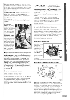 51
51 52
52 53
53 54
54 55
55 56
56 57
57 58
58 59
59 60
60 61
61 62
62 63
63 64
64 65
65 66
66 67
67 68
68 69
69 70
70 71
71 72
72 73
73 74
74 75
75 76
76 77
77 78
78 79
79 80
80 81
81 82
82 83
83 84
84 85
85 86
86 87
87 88
88 89
89 90
90 91
91 92
92 93
93 94
94 95
95 96
96 97
97 98
98 99
99 100
100 101
101 102
102 103
103 104
104 105
105 106
106 107
107 108
108 109
109 110
110 111
111 112
112 113
113 114
114 115
115 116
116 117
117 118
118 119
119 120
120 121
121 122
122 123
123 124
124 125
125 126
126 127
127 128
128 129
129 130
130 131
131 132
132 133
133 134
134 135
135 136
136 137
137 138
138 139
139 140
140 141
141 142
142 143
143 144
144 145
145 146
146 147
147 148
148 149
149 150
150 151
151 152
152 153
153 154
154 155
155 156
156 157
157 158
158 159
159 160
160 161
161 162
162 163
163 164
164 165
165 166
166 167
167 168
168 169
169 170
170