1988 FIAT TEMPRA fuel cap release
[x] Cancel search: fuel cap releasePage 12 of 171

EMERGENCY STARTING
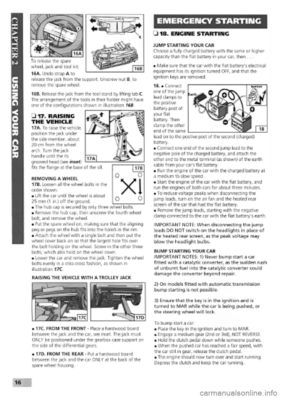
To release the spare
wheel, jack and tool kit:
16A. Undo strap A to
release the jack from the support. Unscrew nut B, to
remove the spare wheel.
16B. Release the jack from the tool stand by lifting tab C.
The arrangement of the tools in their holder might have
one of the configurations shown in illustration 16B.
• 17. RAISING
THE VEHICLE
17A. To raise the vehicle,
position the jack under
the side member, about
20 cm from the wheel
arch. Turn the jack
handle until the its
grooved head (see inset)
fits the flange at the base of the sill.
REMOVING A WHEEL
17B. Loosen all the wheel bolts in the
order shown.
• Lift the car until the wheel is about
25 mm
(1
in.) off the ground.
• The hub cap is secured by only three wheel bolts.
• Remove the hub cap, then unscrew the fourth wheel
bolt, and remove the wheel.
• Put the spare wheel on, making sure that the aligning
peg or pegs on the hub fits into the hole/s in the rim.
• Attach the wheel with a single bolt and then put the
wheel cover back on so that the largest hole fits over
the bolt holding on the wheel. Screw in the other three
bolts, which also hold on the wheel cover.
• Lower the car and remove the jack. Tighten the wheel
bolts evenly in a criss-cross fashion, as shown in
illustration 17C.
RAISING THE VEHICLE WITH A TROLLEY JACK
• 17C. FROM THE FRONT
-
Place a hardwood board
between the jack and the car, see inset. The jack must
ONLY be positioned under the gearbox case support on
the side of the differential gears.
• 17D. FROM THE REAR
-
Put a hardwood board
between the jack and the car ONLY at the back of the
spare wheel housing.
• 18. ENGINE STARTING
JUMP STARTING YOUR CAR
Choose a fully charged battery with the same or higher
capacity than the flat battery in your car, then ...
• Make sure that the car with the flat battery's electrical
equipment has its ignition turned OFF, and that the
ignition keys are removed.
18. • Connect
one of the jump
lead clamps to
the positive
battery post of
your flat
battery. Then
clamp the other
end of the same
lead on to the positive post of the second (charged)
battery.
• Connect one end of the second jump lead to the
negative pole of the charged battery, and attach the
other end to the metal terminal (as shown) of the earth
cable from your car's flat battery.
• Run the engine of the car with the charged battery at
a medium to slow speed.
• Start the engine of the car with the flat battery, and
run the engines of both cars for about three minutes.
• To reduce voltage peaks when disconnecting the
jump leads, turn on the air fan and the heated rear
screen of the car that had the flat battery.
• Remove the jump leads, starting with the negative
clamp connected to the car with the flat battery's earth.
IMPORTANT NOTE: When disconnecting the jump
leads DO NOT switch on the headlights in place of
the heated rear screen, as the peak voltage may
blow the headlight bulbs.
BUMP STARTING YOUR CAR
IMPORTANT NOTES: 1) Never bump start a car
fitted with a catalytic converter, as the sudden rush
of unburnt fuel into the catalytic converter could
damage the converter beyond repair.
2) On models fitted with automatic transmission
bump starting is not possible.
3) Ensure that the key is in the ignition and is
turned to MAR while the car is being pushed, or
the steering wheel will lock.
To bump start a car:
• Place the key in the ignition and turn to MAR.
• Engage a medium gear (2nd or 3rd), NOT REVERSE.
• Hold the clutch pedal down while someone pushes.
• When the pushed car has reached a fair speed, with
the car still in gear, release the clutch pedal.
• The engine should now turn over and start running.
Depress the clutch and keep the car running.
16
Page 58 of 171

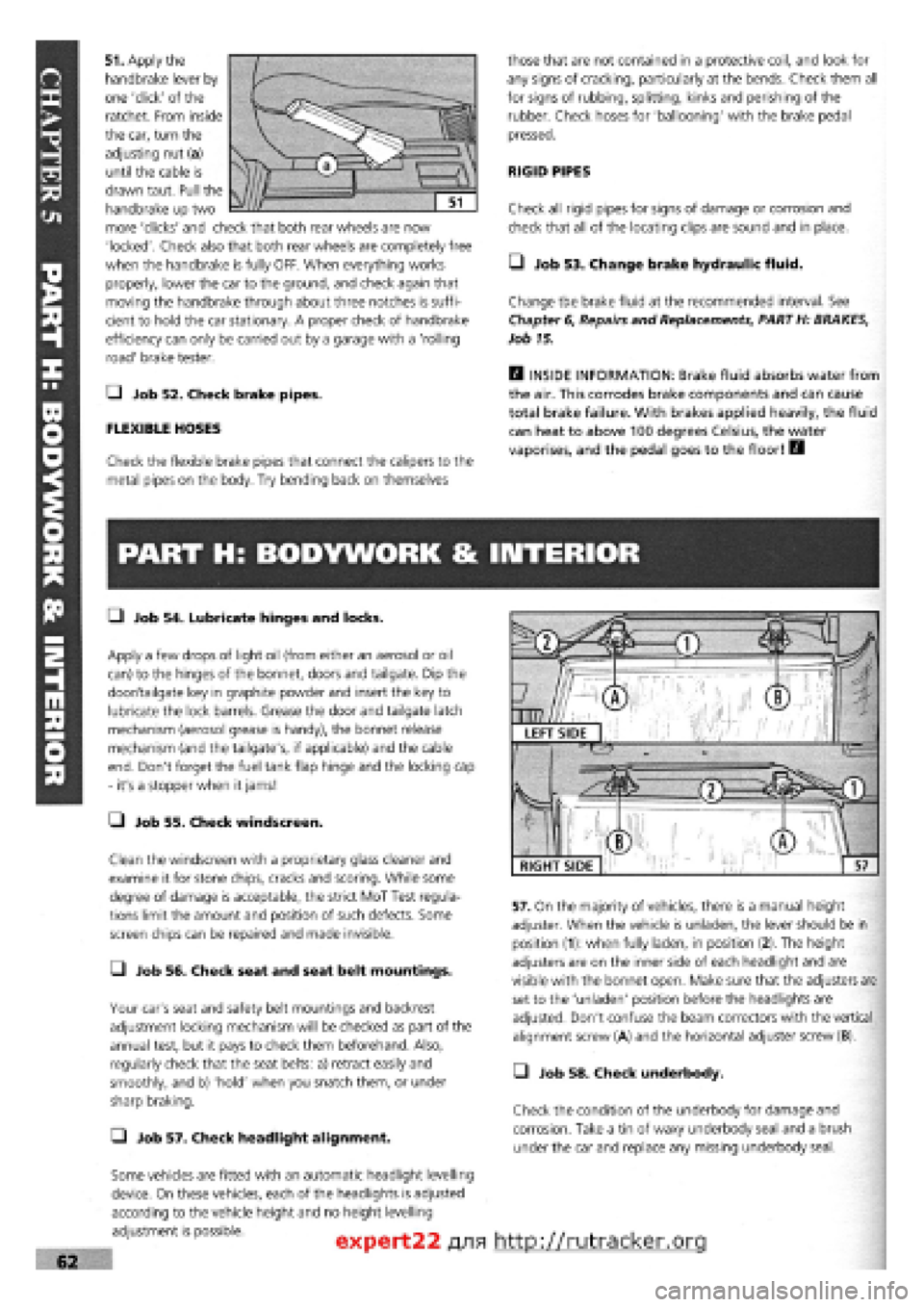
51. Apply the
handbrake lever by
one 'click' of the
ratchet. From inside
the car, turn the
adjusting nut (a)
until the cable is
drawn taut. Pull the
handbrake up two
more 'clicks' and check that both rear wheels are now
'locked'. Check also that both rear wheels are completely free
when the handbrake is fully OFF. When everything works
properly, lower the car to the ground, and check again that
moving the handbrake through about three notches is suffi-
cient to hold the car stationary. A proper check of handbrake
efficiency can only be carried out by a garage with a 'rolling
road' brake tester.
Q Job 52. Check brake pipes.
FLEXIBLE HOSES
Check the flexible brake pipes that connect the calipers to the
metal pipes on the body. Try bending back on themselves
those that are not contained in a protective coil, and look for
any signs of cracking, particularly at the bends. Check them all
for signs of rubbing, splitting, kinks and perishing of the
rubber. Check hoses for 'ballooning' with the brake pedal
pressed.
RIGID PIPES
Check all rigid pipes for signs of damage or corrosion and
check that all of the locating clips are sound and in place.
• Job 53. Change brake hydraulic fluid.
Change the brake fluid at the recommended interval. See
Chapter
6,
Repairs and Replacements, PART H: BRAKES,
Job 15.
H INSIDE INFORMATION: Brake fluid absorbs water from
the air. This corrodes brake components and can cause
total brake failure. With brakes applied heavily, the fluid
can heat to above 100 degrees Celsius, the water
vaporises, and the pedal goes to the floor! B
PART H: BODYWORK & INTERIOR
• Job 54. Lubricate hinges and locks.
Apply a few drops of light oil (from either an aerosol or oil
can) to the hinges of the bonnet, doors and tailgate. Dip the
door/tailgate key in graphite powder and insert the key to
lubricate the lock barrels. Grease the door and tailgate latch
mechanism (aerosol grease is handy), the bonnet release
mechanism (and the tailgate's, if applicable) and the cable
end. Don't forget the fuel tank flap hinge and the locking cap
- it's a stopper when it jams!
• Job 55. Check windscreen.
Clean the windscreen with a proprietary glass cleaner and
examine it for stone chips, cracks and scoring. While some
degree of damage is acceptable, the strict MoT Test regula-
tions limit the amount and position of such defects. Some
screen chips can be repaired and made invisible.
• Job 56. Check seat and seat belt mountings.
Your car's seat and safety belt mountings and backrest
adjustment locking mechanism will be checked as part of the
annual test, but it pays to check them beforehand. Also,
regularly check that the seat belts: a) retract easily and
smoothly, and b) 'hold' when you snatch them, or under
sharp braking.
Q Job 57. Check headlight alignment.
Some vehicles are fitted with an automatic headlight levelling
device. On these vehicles, each of the headlights is adjusted
according to the vehicle height and no height levelling
adjustment is possible.
57. On the majority of vehicles, there is a manual height
adjuster. When the vehicle is unladen, the lever should be in
position (1): when fully laden, in position (2). The height
adjusters are on the inner side of each headlight and are
visible with the bonnet open. Make sure that the adjusters are
set to the 'unladen' position before the headlights are
adjusted. Don't confuse the beam correctors with the vertical
alignment screw (A) and the horizontal adjuster screw (B).
• Job 58. Check underbody.
Check the condition of the underbody for damage and
corrosion. Take a tin of waxy underbody seal and a brush
under the car and replace any missing underbody seal.
expert22 fl/ia http://rutracker.org
RIGHT SIDE
Page 69 of 171

G Step 17: Now repeat this operation on the remaining
valves.
G Step 18: Wash the whole cylinder head again using
paraffin and an old brush, making sure that all traces of
grinding paste are removed, then dry off. Use compressed air
if
available.
SAFETY FIRST!
•
Treat
compressed air with respect. Always wear
goggles
to protect your eyes.
•
Never
allow the airline nozzle near any of the body Sep apertures.
H INSIDE INFORMATION! Check the height of the valve
springs against new ones if possible, but if not, compare
them with each other. If any are shorter than the others,
play safe and replace the complete set. They are bound
to have suffered fatigue which could cause premature
valve failure. H
G Step 19: To install the valves, start from one end.
Lubricate a valve stem with fresh engine oil and slide it in to its
guide.
G Step 20: Locate a new valve stem seal over the stem of
the valve
(if applicable) and push down into contact with the
guide. Position the seal on its seat using a suitable metal tube.
G Step 21: Refit the flat washer and spring seat.
G Step 22: Position the inner and outer springs and the
spring
cap.
G Step 23: Re-apply the valve spring compressor and
compress
the springs enough to allow you to engage the split
collets
in
the stem grooves.
D INSIDE INFORMATION! Grease the grooves so that the
collets will 'stick' in place. The collets are easily fitted by
'sticking' the backs of them onto the end of a screw-
driver with some grease and feeding them into
position. B
G Step 24: Carefully release the spring compressor and
check
that the collets are correctly located. Tap the end of the
stem with
a hammer, to bed them in.
G Step 25: Fit the remaining valves.
Job 5. Petrol engine -
dismantling.
G Step 1: Familiarise yourself with the layout of the engine.
Refer to
illustration Job
2-1
for an exploded view of the
engine
components.
G Step 2: Drain the engine oil. Remove the cylinder head.
See
Job 2.
G Step 3: Remove the distributor. See PART D: IGNITION
• Step 4:
Remove the petrol
pump and spacer
block, if the
mechanical type
(a). (Electric fuel
pumps are in the
fuel tank.)
• Step 5:
Remove and
discard the oil filter
illustration Job
5-4,
• Step 6: Remove the water pump complete with its distri-
bution pipe, and the power steering pump (if fitted).
Q Step 7: Remove the alternator, the crankshaft pulley, the
crankshaft and camshaft sprockets, the cam belt tensioner
and the cam belt cover backplate.
• Step 8:
Remove the
auxiliary shaft
sprocket...
• Step 9: ...the
end plate and
seal, and remove
the auxiliary shaft.
• Step 10:
Undo and remove
the clutch, and
then the flywheel.
• Step 11: Turr
engine assembly c
remove the sump
and remove the crankcase breather (see
part b) with its pipe.