1988 FIAT TEMPRA open gas tank
[x] Cancel search: open gas tankPage 39 of 171

—I Job 13. Check cooling system.
SAFETY FIRST!
• The coolant level should be checked
-
and the
cooling system worked on, ONLY WHEN THE
COOLANT IS COLD. If you remove the pressure cap or
bleed screws when the engine is hot, scalding coolant
will spurt out.
• Keep anti-freeze away from children. If it is acciden-
tally swallowed or contacts skin or eyes, rinse
immediately with plenty of water and seek immediate
medical help.
Examine the cooling system hoses, looking for signs of
splitting, chafing and perishing. Squeeze the top and bottom
radiator hoses. Any hard, brittle areas or crackling sounds tell
you that the hoses are decomposing from the inside
-
replace-
ments needed!
SAFETY FIRST!
If
a
clearance is outside the tolerances shown in Chapter 3,
Facts
and Figures, the relevant shim will have to be changed.
New
shims
are available from your FIAT dealer. This work is
fully described in Chapter
6,
Repairs and Replacements.
10E. You must
always use a new
gasket, especially in
view of the oil level
mentioned earlier.
Clean the housing
and
cover faces and
use
the gasket dry.
11.
Examine the
belt
for wear. If
there
is
any
cracking, or if the
toothed side
10F.H INSIDE
INFORMATION:
The cover is 'anti-
crush'
-
you CAN'T
tighten beyond
the lugs pointed
out here
-
so
there's no point
trying! H
0 Job 11. Check camshaft timing belt.
Remove the camshaft belt outer cover. See Chapter 6,
Repairs
and Replacements, PART A: ENGINE.
FACT FILE: VALVE IDENTIFICATION:
T
—
Remember that clearances for inlet and
3™ exhaust valves differ. See
Chapter
3,
Facts and Figures. Counting from the
—^ timing belt end the valves are:
1.1,1.2 8-valve AND DIESEL ENGINES:
EXHAUST -1, 3, 6, 8. INLET
-
2, 4, 5, 7.
1372cc AND 1581cc ENGINES: EXHAUST -1, 4, 5, 8.
INLET
-
2, 3, 6, 7.
1.2 16-valve Hydraulic tappets
-
non-adjustable.
13. If original FIAT hose
clips (a) are fitted, cut them
off (taking great care not to
damage the stub beneath!)
and replace with screw-
tight clips, when fitting a
new hose. Ensure that hose
clips are secure and firm but
not over-tightened.
Check that the wires to the
cooling fan switch (b) are in
good shape. Also, refer to
Job
27
• Job 14. Change engine coolant.
• See SAFETY FIRST! at the start of Job 13.
appears worn, or
any 'teeth' are
missing, replace
the belt straight
away. If the belt
breaks
the valves may collide with the pistons, causing serious
engine damage. Camshaft belt replacement is described in
Chapter 6,
Repairs and Replacements, or you may wish to
have
your FIAT dealer carry out the work for you. If you can
twist the belt through more than 90 degrees, it needs re-
tensioning. Also see Chapter
6,
Repairs and Replacements.
m
AUtOKAlIC CtMAU s/
b
14A. Remove the expansion tank filler cap. Move the heater
control (a) to the red (open) position or, on automatic
systems, press the TEMP button (b) on the dash until HI
appears on the display (c).
—i Job 12. Change camshaft timing belt.
It is
ESSENTIAL that you renew the camshaft drive belt at the
recommended interval. See the Service Interval Chart at the
start
of this chapter. Chapter
6,
Repairs and Replacements
explains how to carry out the work.
14B. Loosen the
worm-drive clip
(arrowed) and
pull off the
bottom radiator
hose.
Page 50 of 171

CHOKE (MANUAL) FAST IDLE ADJUSTMENT
Move the choke control lever by hand to the end of its travel
and hold it there. The main butterfly aperture (A) should now
be about 1.1 mm. If not, slacken the lock-nut (3), regulate the
adjustment screw (1), and retighten the lock-nut.
AUTOMATIC ANTI-FLOODING DEVICE ADJUSTMENT
With the choke control lever still at the end of its travel as
described in the previous paragraph, the strangler butterfly
aperture (B) should be between 3 and 3.5 mm. If not, regulate
the adjustment screw (2).
FUEL INJECTION MODELS
The idle speed and mixture settings are controlled by the
Electronic Control Unit (ECU) which is 'self-learning' and is
programmed to adjust itself to give the ideal settings under all
conditions. No manual adjustment is possible, nor provided
for. If there is a problem, see Job 29 You may need to take
your car to a FIAT dealer, with the appropriate diagnostic
equipment.
35D. At each service interval, the accelerator pivot (A).
35E. ...should be lubri-
cated with a dab of
TUTELA MRM2
grease.
The ACCELERATOR
LINKAGE must be
adjusted correctly if
the Mono-Jetronic
injection system is to operate smoothly and correctly.
• Disconnect the rod (1) from the lever (2). The pulley (3)
should now be against its closed stop.
• Check that the accelerator cable is not loose, but neither
should it be taut, and check that there is no free play in the
accelerator pedal.
• If necessary, adjust the accelerator cable by slackening the
lock-nut (B) and turning the adjuster nut (C) until the cable is
correctly tensioned. Then retighten the lock-nut.
Now reconnect the rod to the lever on the fuel injection unit
and let the engine warm up until the cooling fan has cut in at
least twice, then turn the engine off.
• With the accelerator pedal released check that the
clearance between the levers (2) and (4) is between 0.2 and
0.5 mm.
• If necessary, loosen the lockouts (5) and (6). Use a spanner
on the adjuster nut (7) to tighten or loosen the rod (1) until
the clearance is between 0.2 and 0.5 mm.
• Retighten the adjuster nuts (5) and (6).
• Finally, make sure that with the accelerator pedal
completely depressed, the butterfly in the fuel injection unit is
fully open.
• If not, the accelerator cable may be too taut or the
clearance between the levers (2) and (4) may be re-adjusted,
keeping them within the acceptable tolerances.
Q Job 36. Check emission control systems.
PETROL INJECTION MODELS ONLY
36A. On petrol-
injected Tipos and
Tempras, sophisti-
cated emission
control equipment is
fitted and must be
tested with a proper
emissions tester.
FACT FILE: EMISSION CONTROL
SYSTEM
36B. The main features of the system are:
• an Electronic Control Module Unit or (ECU) (1) -
the 'computer brain', which is programmed to alter the
car's fuel and ignition settings according to information
received from various sensors.
• a catalytic converter (2) in the exhaust system, to
convert CO and other gases to less harmful gases.
• a Lambda sensor (3) in the exhaust manifold or front
pipe (according to model) to detect the 'tune' of the
exhaust gases and give a signal to the ECU.
• a petrol evaporation control system, to cut down on
petrol vapour emissions from the fuel tank.
• part 4 is the 'upstream' emission test point. See Job
29.
Page 114 of 171
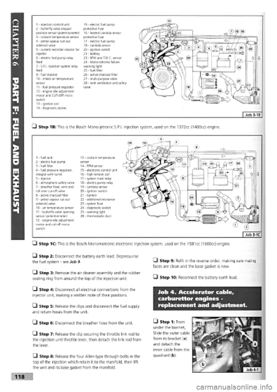
1 - injection control unit 15 - electric fuel pump 2 - butterfly valve angular protective fuse position sensor (potentiometer) 16 - heated Lambda sensor 3 - coolant temperature sensor protective fuse 4 - petrol vapour cut-out 17 - electric fuel pump solenoid valve 18 - Lambda sensor 5 - current restricter resistor for 20 - ignition switch injector 21 - battery 6 - electric fuel pump relay 23 - RPM and T.D.C. sensor feed 24 - Mono-Jetronic failure 7 - S.P.I, injection system relay warning light feed 25
-
fuel filter 9 - fuel injector 26 - active charcoal filter 10 - intake air temperature 27 - multi-purpose valve sensor 28 - tank ventilation and safety 11 - fuel pressure regulator valve 12 - engine idle adjustment motor and CUT-OFF micro switch 13 - ignition coil 14 - diagnostic socket
Q Step 1B: This is the Bosch Mono-jetronic S.P.I, injection system, used on the 1372cc (1400cc) engine.
1 - fuel tank 13 coolant temperature 2 - electric fuel pump sensor 3 - fuel filter 14 RPM sensor 4 - fuel pressure regulator, 15 electronic control unit integral with turret 16 - high tension coil 5 - injector 17 - system main relay 6 - atmospheric safety valve 18 - electric pump relay 7 - breather float, vent and 19 - Lambda sensor roll over cut-off valve 20 - ignition switch 8 - active charcoal filter 21 - battery 9 - petrol vapour cut out 22 - additional resistance solenoid valve 23 - system fuse 10 - air temperature sensor 24 - diagnostic socket 11 - butterfly valve opening 25 - warning light sensor (potentiometer) 26 - thermostatic duct 12 - engine idle adjustment motor and cut-off micro switch
Q Step 1C: This is the Bosch Monomotronic electronic injection system, used on the
1581
cc (1600cc) engine.
• Step 2: Disconnect the battery earth lead. Depressurise
the fuel system
-
see Job 9.
• Step 3: Remove the air cleaner assembly and the rubber
sealing ring from around the top of the injection unit.
Q Step 4: Disconnect all electrical connections from the
injector unit, making a written note of their positions.
Q Step 5: Release the clips and disconnect the fuel supply
and return hoses from the unit.
G Step 6: Disconnect the breather hose from the unit.
• Step 7: Release the clip securing the throttle link rod to
the injection unit throttle lever, then detach the link rod from
the lever.
Q Step 8: Release the four Allen-type through-bolts in the
top of the injection which retain it to the manifold, then lift
the unit and its base gasket from the manifold.
• Step 9: Refit in the reverse order, making sure mating
faces are clean and the base gasket is new.
• Step 10: Reconnect the battery earth lead.
Job 4. Accelerator cable,
carburettor engines -
replacement and adjustment.
• Step 1: From
under the bonnet,
Slide the outer cable
from its bracket (a)
and detach the
inner cable from the
quadrant (b).
118