1988 FIAT TEMPRA run flat
[x] Cancel search: run flatPage 6 of 171

• Repeat this operation three more times until the
complete code number has been entered, if the code
has been entered in correctly LED B will start flashing.
• Release button A (see illustration
1B).
Red LED B
flashes for 8 seconds indicating the new remote unit's
code has been stored.
IMPORTANT NOTE: If the LED does not illuminate
when remote unit button (illustration 1B, button
O is pressed, change the remote unit's battery.
• Insert the emergency key A into the emergency switch
slot in the glove compartment turn the key to the left to
switch the alarm off (see inset).
• Turn the key back towards its original position to
switch the alarm system back on.
IMPORTANT NOTE: As the alarm system absorbs
energy, if you are not planning on using the car
for a long period of time, turn the alarm exclusion
key to the off position, so as not to run the vehicle
battery down.
• 2. IGNITION SWITCH AND
STEERING COLUMN LOCK
IGNITION SWITCH
2. The ignition/steering column lock key, once inserted
in the ignition lock, can be placed in any of the
following four positions:
• PARK
-
With the key in this
position the side and tail lights
can be turned on, the steering
column locked and the keys
can be removed. Press button
A to turn the key to PARK.
• STOP
-
When the key is
turned to the STOP position the steering column will be
locked, and the keys can be removed.
• MAR
-
This is the driving position. When the key is in
this position all the electrical devices are energised.
• AW
-
Turning the key to this position starts the
engine.
STEERING COLUMN LOCK
• LOCKING
-
To apply the steering wheel lock turn the
steering wheel slightly to the left or right when the key is
at STOP or PARK.
• UNLOCKING
-
Rocking the steering wheel gently back
and forth while turning the ignition key to MAR unlocks
the steering wheel.
• 3. PANEL INDICATORS
INSTRUMENT DISPLAY PANEL
3. These are the instrument panel warning LED indicators
for all FIAT Tipo/Tempra models. Your vehicle will only
have Panel Indicators relevant to your particular car.
• 4. ELECTRONIC CHECK PANEL
4. The electronic check panel is not fitted to models
with basic trim.
IMPORTANT NOTE: The check panel will not
indicate if the tail light fuses blow at the same
time, or if there is a circuit failure within the panel
display.
SIDE AND HATCHBACK DOORS
When the ignition key is at MAR, the check panel LEDs
g, h, i, I, m and n monitor the light bulbs and fuses.
LEDs a, b, c, d, and e monitor incomplete closure of
the side doors and hatchback.
• Never remove the key when the car is moving.
If you do, the steering wheel will lock the first
time you turn it.
• If the ignition lock has been tampered with or
shows any sign of damage (e.g. attempted theft),
have the lock checked at your nearest FIAT
Service Centre.
M Choke Oil pressure warning
Direction indicators (®) Handbrake engaged
-X: Side lights m Rear window defroster
10 High beam head
lights '•y Injection system warning light
<1* Rear fog lights • Battery warning
A Hazard warning lights A Seat belts not
buckled
m ABS brake warning a Automatic transmission fluid warning
o Brake pad wear warning a Doors not properly closed
Turbo pressure warning Trailer direction indicators
10 Front fog lights a Diesel fuel filter condenstate warning
•515" Diesel heater/glow •515" plugs 3
SWITCHING OFF THE ALARM
1C. Some models
are fitted with an
alarm exclusion
switch, which can
be found inside
the glove
compartment. If
the alarm is faulty
or the remote control batteries are flat:
Page 12 of 171

EMERGENCY STARTING
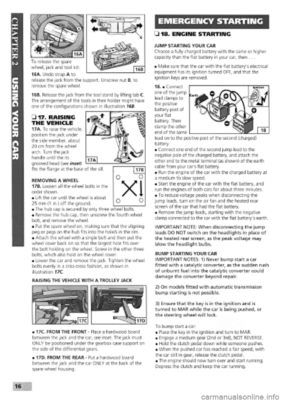
To release the spare
wheel, jack and tool kit:
16A. Undo strap A to
release the jack from the support. Unscrew nut B, to
remove the spare wheel.
16B. Release the jack from the tool stand by lifting tab C.
The arrangement of the tools in their holder might have
one of the configurations shown in illustration 16B.
• 17. RAISING
THE VEHICLE
17A. To raise the vehicle,
position the jack under
the side member, about
20 cm from the wheel
arch. Turn the jack
handle until the its
grooved head (see inset)
fits the flange at the base of the sill.
REMOVING A WHEEL
17B. Loosen all the wheel bolts in the
order shown.
• Lift the car until the wheel is about
25 mm
(1
in.) off the ground.
• The hub cap is secured by only three wheel bolts.
• Remove the hub cap, then unscrew the fourth wheel
bolt, and remove the wheel.
• Put the spare wheel on, making sure that the aligning
peg or pegs on the hub fits into the hole/s in the rim.
• Attach the wheel with a single bolt and then put the
wheel cover back on so that the largest hole fits over
the bolt holding on the wheel. Screw in the other three
bolts, which also hold on the wheel cover.
• Lower the car and remove the jack. Tighten the wheel
bolts evenly in a criss-cross fashion, as shown in
illustration 17C.
RAISING THE VEHICLE WITH A TROLLEY JACK
• 17C. FROM THE FRONT
-
Place a hardwood board
between the jack and the car, see inset. The jack must
ONLY be positioned under the gearbox case support on
the side of the differential gears.
• 17D. FROM THE REAR
-
Put a hardwood board
between the jack and the car ONLY at the back of the
spare wheel housing.
• 18. ENGINE STARTING
JUMP STARTING YOUR CAR
Choose a fully charged battery with the same or higher
capacity than the flat battery in your car, then ...
• Make sure that the car with the flat battery's electrical
equipment has its ignition turned OFF, and that the
ignition keys are removed.
18. • Connect
one of the jump
lead clamps to
the positive
battery post of
your flat
battery. Then
clamp the other
end of the same
lead on to the positive post of the second (charged)
battery.
• Connect one end of the second jump lead to the
negative pole of the charged battery, and attach the
other end to the metal terminal (as shown) of the earth
cable from your car's flat battery.
• Run the engine of the car with the charged battery at
a medium to slow speed.
• Start the engine of the car with the flat battery, and
run the engines of both cars for about three minutes.
• To reduce voltage peaks when disconnecting the
jump leads, turn on the air fan and the heated rear
screen of the car that had the flat battery.
• Remove the jump leads, starting with the negative
clamp connected to the car with the flat battery's earth.
IMPORTANT NOTE: When disconnecting the jump
leads DO NOT switch on the headlights in place of
the heated rear screen, as the peak voltage may
blow the headlight bulbs.
BUMP STARTING YOUR CAR
IMPORTANT NOTES: 1) Never bump start a car
fitted with a catalytic converter, as the sudden rush
of unburnt fuel into the catalytic converter could
damage the converter beyond repair.
2) On models fitted with automatic transmission
bump starting is not possible.
3) Ensure that the key is in the ignition and is
turned to MAR while the car is being pushed, or
the steering wheel will lock.
To bump start a car:
• Place the key in the ignition and turn to MAR.
• Engage a medium gear (2nd or 3rd), NOT REVERSE.
• Hold the clutch pedal down while someone pushes.
• When the pushed car has reached a fair speed, with
the car still in gear, release the clutch pedal.
• The engine should now turn over and start running.
Depress the clutch and keep the car running.
16
Page 48 of 171

• Job 32. Change petrol fuel filter. IMPORTANT NOTES:
• Wear plastic gloves and goggles and have a large rag
and a suitable fire extinguisher ready.
• Place a container beneath the filter to catch fuel
spillage.
• After fitting the new filter in place, refit the casing,
ensure no traces of fuel are left, reconnect the battery and
restart the engine.
• Check carefully to ensure there are no leaks before
refitting the cover.
• Job 33. Drain diesel fuel filter.
IMPORTANT NOTE: Some models are fitted with a water-
in-fuel sensor. Drain the filter when the warning light
comes on. Unplug the sensor from the base of the filter,
first.
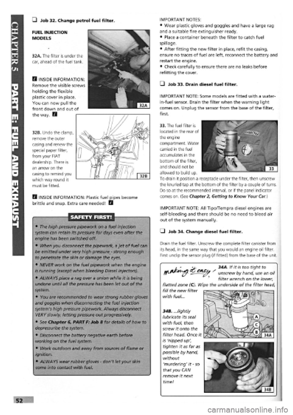
FUEL INJECTION
MODELS
32A. The filter is under the
car, ahead of the fuel tank.
E3 INSIDE INFORMATION:
Remove the visible screws
holding the flexible
plastic cover in place.
You can now pull the
front down and out of
the way. E3
32B. Undo the clamp,
remove the outer
casing and renew the
special paper filter,
from your FIAT
dealership. There is
an arrow on the
casing to remind you
which way round it
must be fitted.
33. The fuel filter is
located in the rear of
the engine
compartment. Water
carried in the fuel
accumulates in the
bottom of the filter,
and should not be
allowed to build up.
To drain it position a receptacle under the filter, then unscrew
the knurled tap at the bottom of the filter by a couple of turns.
Do so at the recommended interval, or if the panel indicator
comes on. (See Chapter
2,
Getting to Know Your
Car.)
H INSIDE INFORMATION: Plastic fuel pipes become
brittle and snap. Extra care needed! E3
SAFETY FIRST!
• The high pressure pipework on a fuel injection
system can retain its pressure for days even after the
engine has been switched off.
• When you disconnect the pipework, a jet of fuel can
be emitted under very high pressure
-
strong enough
to penetrate the skin or damage the eyes.
• NEVER work on the fuel pipework when the engine
is running (except when bleeding Diesel injectors).
• ALWAYS place a rag over a union while it is being
undone until all the pressure has been let out of the
system.
• You are recommended to wear strong rubber gloves
and goggles when disconnecting the fuel injection
system's high pressure pipework. Always disconnect
VERY slowly, letting pressure out progressively.
• See Chapter 6, PART F: Job 8 for details of how to
depressurise the system.
• Disconnect the battery negative earth before
working on the fuel system.
• Work outdoors and away from sources of flame or
ignition.
• ALWAYS wear rubber gloves
-
don't let your
skin
come into contact with fuel.
IMPORTANT NOTE: All Tipo/Tempra diesel engines are
self-bleeding and there should be no need to bleed air
out of the system manually.
• Job 34. Change diesel fuel filter.
Drain the fuel filter. Unscrew the complete filter canister from
its head, in the same way that you would an engine oil filter.
First undip the sensor plug (if fitted) from the base of the unit.
^ 34A. If it is too tight to
^^ - unscrew by hand, use an oil
filter wrench on the lower,
flatted zone (C). Wipe the underside of the filter head,
fill the new filter
with fuel...
34B. ...lightly
lubricate its seal
with fuel, then
screw it onto the
filter head. Once it
is 'nipped up',
tighten it as far as
possible by hand,
without
'murdering' it
-
so
that you CAN
remove it next
time!
Page 105 of 171

SAFETY FIRST!
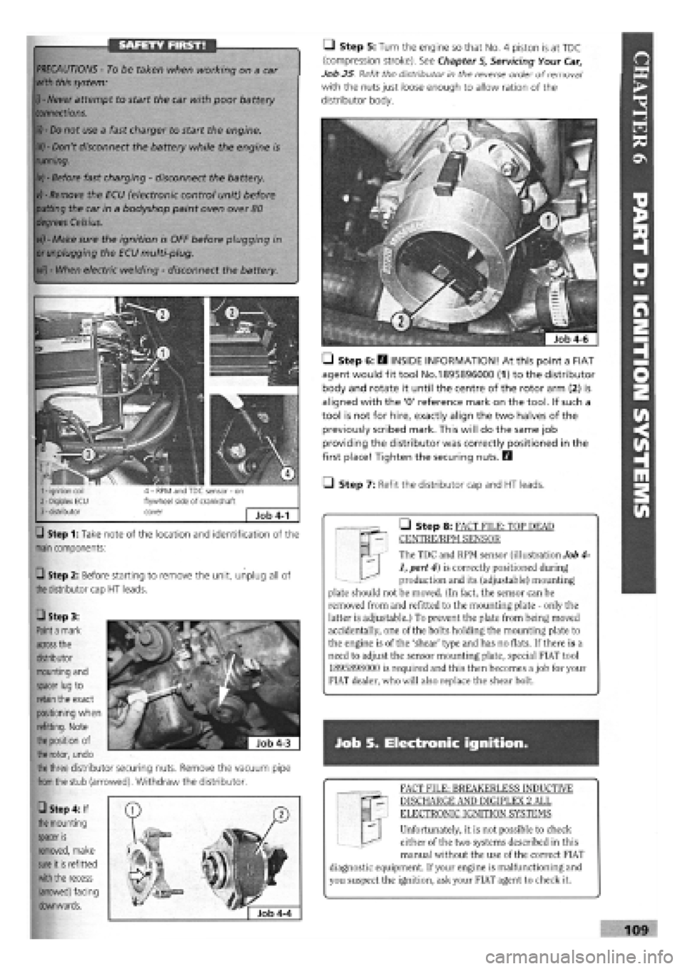
Step 1: Take note of the location and identification of the
main
components:
Q Step 2: Before starting to remove the unit, unplug all of
the
distributor cap
HT
leads.
M | The TDC and RPM sensor (illustration Job 4-
1, part 4) is correctly positioned during
production and its (adjustable) mounting
plate should not be moved. (In fact, the sensor can be
removed from and refitted to the mounting plate - only the
latter is adjustable.) To prevent the plate from being moved
accidentally, one of the bolts holding the mounting plate to
the engine is of the 'shear' type and has no flats. If there is a
need to adjust the sensor mounting plate, special FIAT tool
1895898000 is required and this then becomes a job for your
FIAT dealer, who will also replace the shear bolt.
• Step 8: FACT FILE: TOP DEAD
CENTRE/RPM SENSOR
PRECAUTIONS -
To be taken when working on a car
with this system:
i) - Never
attempt to start the car with poor battery
connections.
ii) - Do
not use a fast charger to start the engine.
iii) -
Don't disconnect the battery while the engine is
running.
iv) -
Before fast charging
-
disconnect the battery.
vj - Remove
the ECU (electronic control unit) before
putting
the car in a bodyshop paint oven over
80
degrees Celsius.
vi) -
Make sure the ignition is OFF before plugging in
or unplugging
the ECU multi-plug.
vii) -
When electric welding
-
disconnect the battery.
Q Step 5: Turn the engine so that No. 4 piston is at TDC
(compression stroke). See Chapter
5,
Servicing Your Car,
Job 25 Refit the distributor in the reverse order of removal1
with the nuts just loose enough to allow ration of the
distributor body.
• Step 6: E3 INSIDE INFORMATION! At this point a FIAT
agent would fit tool No.1895896000 (1) to the distributor
body and rotate it until the centre of the rotor arm (2) is
aligned with the '0' reference mark on the tool. If such a
tool is not for hire, exactly align the two halves of the
previously scribed mark. This will do the same job
providing the distributor was correctly positioned in the
first place! Tighten the securing nuts. Q
• Step 7: Refit the distributor cap and HT leads.
Job S. Electronic ignition.
FACT FILE: BREAKERLESS INDUCTIVE
DISCHARGE AND DIGIPLEX 2 ALL
ELECTRONIC IGNITION SYSTEMS
Unfortunately, it is not possible to check
either of the two systems described in this
manual without the use of the correct FIAT
diagnostic equipment. If your engine is malfunctioning and
you suspect the ignition, ask your FIAT agent to check it.
109
• Step 3:
Paint a
mark
across
the
distributor
mounting and
spacer lug
to
retain
the exact
positioning when
refitting. Note
the position
of
the rotor,
undo
the three
distributor securing nuts. Remove the vacuum pipe
from the
stub (arrowed). Withdraw the distributor.
• Step 4: If
the
mounting
spacer
is
removed, make
sure
it
is
refitted
with the
recess
(arrowed) facing
downwards.
Page 134 of 171

• Step 3: ...and
remove the caliper
support bracket.
Ll Step 4: Unscrew
the disc fixing bolts and
withdraw the disc.
clean and undamaged.
• Before refitting the disc,
ensure that the mating
surfaces
-
hub to disc, are
Job 10. Master cylinder
replacement.
H INSIDE INFORMATION: • On right-hand drive cars, the
master cylinder is on the driver's side and is VERY
different to get at, behind the engine.
• To remove the master cylinder on these cars you may
need to remove the complete assembly
-
master cylinder,
servo and pedal assembly
-
from inside the car. Q
• Step 1: IMPORTANT NOTE: Protect all paint surfaces
from possible brake fluid spillage before starting work.
You know what a good paint stripper it is!
• Step 2: Syphon off as much brake fluid as possible or
bleed it out
through one of the
front brakes until
the master cylinder
makes 'sucking'
noises.
• Step 3:
Remove the
reservoir from the
master cylinder.
138
• Step 4: Use a spanner
-
preferably a purpose-made split
ring spanner
-
to undo all the pipe unions from the master
cylinder.
• Step 5:
Undo the nuts
securing the
master cylinder
to the servo and
remove it.
• Step 6: Refit
in the reverse
order and refer
to Job
77
for
bleeding the
brakes.
Job 11. Servo check
and refit.
remove
Q INSIDE INFORMATION: • Before condemning the
servo for lack of efficiency, check the condition of the
one-way valve and vacuum pipe connecting it to the
inlet manifold.
• Ease the valve out of the front of the servo and
disconnect the pipe from the inlet manifold.
• Check that you can only blow one way through the
valve
-
from the servo end towards the inlet manifold (or
the brake vacuum pump
-
Diesel models).
• The vacuum pipe can suffer failure in many ways. Age
can harden it until it cracks, causing an air leak which
sometimes results in a whistling noise and rough slow-
running.
• Loose connections could also produce the same result.
• The other type of vacuum hose failure is an implosion
(where the hose is sucked flat by the vacuum) often
because oil has softened the hose.
• This is not so easily detected, as it rarely upsets the
engine performance and resumes its normal shape
shortly after the engine is stopped.
• The inner lining can also deteriorate, causing a
blockage. Q
• Step 1: Follow Job
10
to remove the master cylinder.
• Step 2: From inside the car, unhook the accelerator cable
from the pedal fork.
• Step 3:
Undo the
fixing nuts,
remove the
retaining
plate and
pedal
assembly.
•
eP^BH
1
| Mitx
IfP^K p{B||n (Or Hot
I
a^®. i kS^^^Ap
i
/is ^8*5211^3
in A
Mil
11 SaBPffe
l|i§
# J
Job 11-3