Page 49 of 171

IMPORTANT NOTE: • All Tipo/Tempra diesel engines are
self-bleeding and there should be no need to bleed air
out of the system manually.
• If the engine does not eventually re-start, check all the
unions for the fuel inlet pipe and the other unions,
replacing the sealing washers if necessary, to eliminate
any air leaks.
Q Job 35. Check/adjust petrol engine idle and
emissions.
Setting the idle speed and mixture is not just a matter of
making
the car run smoothly and economically; it's also a
question of allowing it to run within the legal hydrocarbon
(HC), Nitrous Oxide (NO) and carbon monoxide (CO) emission
limits. If it
is
outside limits, the car will fail the annual test.
(However, a worn engine will fail even if the carburettor or
injection system is correctly set up.)
FACT FILE: ESSENTIAL
PREPARATIONS
• When tuning the engine you should
adjust the carburettor (when fitted) last
of all, as its settings will be affected by
the state of tune of the rest of the engine.
• Ignition dwell angle and timing must be correct, the
air
filter
should be clean, there should be no air leaks
on
the induction system, and all electrical components
and
the air conditioning (if fitted) should be switched
off.
• Get the engine to full operating temperature before
checking and adjusting.
• If
you
warm the engine on tick-over (instead of on a
journey), it won't be hot enough until you have heard
the electric cooling fan cut in twice.
Q INSIDE INFORMATION: These jobs require the use of a
tachometer (rev-counter) and an exhaust gas analyser to
achieve any degree of accuracy. If you don't own them -
and relatively inexpensive tools are now available
-
you
may
wish
to have the work carried out by your local FIAT
dealer. D
ROUGH
GUIDE: Within each section is a description of how
you
can
get the car running tolerably well without any
specialist
equipment, so that you can take it to your FIAT
dealership
for accurate (and MoT-able!) tuning.
35A. Check the float
level with the carburettor
in the position shown.
Distance (c) should be
30mm with gasket fitted.
Bend tab (2) to adjust
-
but the tab should
remain virtually perpen-
dicular. Do NOT adjust
items (1)or (3)1
35B. IDLE SPEED
ADJUSTMENT: Connect a
rev-counter according to
the maker's instructions,
and check the idle speed.
clockwise increases the
idle speed, anti-clockwise
reduces it. Set the idle
speed in accordance with
Chapter
3,
Facts and
Figures.
ROUGH GUIDE: Turn the screw until the engine is running at
the slowest speed at which it runs smoothly and evenly.
MIXTURE ADJUSTMENT: Check that the idle speed is correct
and make sure that the engine is at full operating temper-
ature. Connect an exhaust gas analyser as instructed by the
maker. If the CO reading is outside the range shown in
Chapter
3,
Facts and Figures, adjustment as follows:
Use a narrow-blade screwdriver and turn the screw (2)
clockwise to weaken (reduce) or anti-clockwise to richen
(increase) the reading.
ROUGH GUIDE: Turn the mixture screw inwards (clockwise).
As you do so, the tick-over speed will increase, until the point
comes where the engine starts to run 'lumpily'. Back off the
screw until the engine runs smoothly again, and then some
more until the speed just starts to drop. At this point, screw
the adjuster back in by a quarter-turn and you'll be
somewhere near the optimum setting for smooth running.
IMPORTANT NOTE: After setting the mixture adjustment,
re-check and, if necessary, re-adjust the idle speed.
CARBURETTOR MODELS ONLY
TAMPER PROOFING: All Tipo carburettors originally had a
tamper-proof seal placed over the mixture adjustment screw.
These
seals are to prevent anyone unauthorised from altering
the
mixture and exhaust emissions. In certain countries these
seals
must be retained by law.
If the
seal
is
a plastic cap placed over the adjuster screw, it can
be
broken
off with pliers. If it is a plug within the screw recess,
force
it out with a sharp object.
35C. This illustration
shows the correct
settings for the
choke fast idle
adjustment (manual
choke only) and the
automatic anti-
flooding device
adjustment. See
following page.
Page 50 of 171
 FAST IDLE ADJUSTMENT
Move the choke control lever by hand to the end of its travel
and hold it there. The main butterfly aperture (A) should now
be about 1.1 mm. If not, slacken the")
CHOKE (MANUAL) FAST IDLE ADJUSTMENT
Move the choke control lever by hand to the end of its travel
and hold it there. The main butterfly aperture (A) should now
be about 1.1 mm. If not, slacken the lock-nut (3), regulate the
adjustment screw (1), and retighten the lock-nut.
AUTOMATIC ANTI-FLOODING DEVICE ADJUSTMENT
With the choke control lever still at the end of its travel as
described in the previous paragraph, the strangler butterfly
aperture (B) should be between 3 and 3.5 mm. If not, regulate
the adjustment screw (2).
FUEL INJECTION MODELS
The idle speed and mixture settings are controlled by the
Electronic Control Unit (ECU) which is 'self-learning' and is
programmed to adjust itself to give the ideal settings under all
conditions. No manual adjustment is possible, nor provided
for. If there is a problem, see Job 29 You may need to take
your car to a FIAT dealer, with the appropriate diagnostic
equipment.
35D. At each service interval, the accelerator pivot (A).
35E. ...should be lubri-
cated with a dab of
TUTELA MRM2
grease.
The ACCELERATOR
LINKAGE must be
adjusted correctly if
the Mono-Jetronic
injection system is to operate smoothly and correctly.
• Disconnect the rod (1) from the lever (2). The pulley (3)
should now be against its closed stop.
• Check that the accelerator cable is not loose, but neither
should it be taut, and check that there is no free play in the
accelerator pedal.
• If necessary, adjust the accelerator cable by slackening the
lock-nut (B) and turning the adjuster nut (C) until the cable is
correctly tensioned. Then retighten the lock-nut.
Now reconnect the rod to the lever on the fuel injection unit
and let the engine warm up until the cooling fan has cut in at
least twice, then turn the engine off.
• With the accelerator pedal released check that the
clearance between the levers (2) and (4) is between 0.2 and
0.5 mm.
• If necessary, loosen the lockouts (5) and (6). Use a spanner
on the adjuster nut (7) to tighten or loosen the rod (1) until
the clearance is between 0.2 and 0.5 mm.
• Retighten the adjuster nuts (5) and (6).
• Finally, make sure that with the accelerator pedal
completely depressed, the butterfly in the fuel injection unit is
fully open.
• If not, the accelerator cable may be too taut or the
clearance between the levers (2) and (4) may be re-adjusted,
keeping them within the acceptable tolerances.
Q Job 36. Check emission control systems.
PETROL INJECTION MODELS ONLY
36A. On petrol-
injected Tipos and
Tempras, sophisti-
cated emission
control equipment is
fitted and must be
tested with a proper
emissions tester.
FACT FILE: EMISSION CONTROL
SYSTEM
36B. The main features of the system are:
• an Electronic Control Module Unit or (ECU) (1) -
the 'computer brain', which is programmed to alter the
car's fuel and ignition settings according to information
received from various sensors.
• a catalytic converter (2) in the exhaust system, to
convert CO and other gases to less harmful gases.
• a Lambda sensor (3) in the exhaust manifold or front
pipe (according to model) to detect the 'tune' of the
exhaust gases and give a signal to the ECU.
• a petrol evaporation control system, to cut down on
petrol vapour emissions from the fuel tank.
• part 4 is the 'upstream' emission test point. See Job
29.
Page 51 of 171

ELECTRONIC CONTROL MODULE: The ECU is not an item
that requires any servicing. If you think it might be faulty, ask
your FIAT dealer or fuel injection specialist to check it for you.
This must be done by someone with the correct FIAT plug-in
diagnostic equipment and data.
CATALYTIC CONVERTER: The CAT is not serviceable. If it
fails, you will be told at the MoT test. Replacement is
expensive, so we recommend you obtain a second opinion
before replacing the 'cat'.
LAMBDA SENSOR: For information concerning the sensor,
see
Job
37.
I' sensor is a simple job (see
Chapter 6, Repairs and
Replacements, PART F: FUEL AND EXHAUST), but it
can only be tested by your FIAT dealer with the correct
equipment
• If the sensor is faulty, have it renewed by your
dealer.
• Lambda sensors are very delicate and easily
damaged. It is not likely that you would be able to
return one to the supplier if you fitted it yourself.
• Lambda sensors are only fitted to cars with a
catalytic converter.
• Job 38. Check/adjust diesel idle speed.
To accurately check and adjust the diesel's idle speed you
need a diesel-specific rev-counter. If you're happy with the idle
speed, leave well alone. But if you're convinced the idle is
incorrect, it's best to take the car to a FIAT dealer. If you wish
to adjust the speed yourself, get the engine to normal
operating temperature, and check there is some free play in
the accelerator cable before proceeding.
ADJUSTMENT
-
BOSCH PUMP
D INSIDE INFORMATION: If the canister is flooded with
petrol, it is probable that one of the purge valves or
purge valve floats is faulty. Get this investigated and
rectified by a FIAT dealer. If the engine cuts out and then
restarts after a while, it could be the breather hose
valve, fitted under the fuel filler neck. This one-way
valve allows air to enter the tank as the fuel level falls,
otherwise an air lock can prevent fuel reaching the
engine. To test the valve, take off the pipe clips, remove
the valve and test it as for the canister one-way valve,
above. It should allow air to pass into the tank, but not
the other way. H
Q Job 37. Check Lambda sensor.
PETROL INJECTION MODELS ONLY
For
a
description of how the sensor works, see Job 36, FACT
FILE: EMISSION CONTROL SYSTEM. It should be checked at
the recommended interval
-
the cost of checking and
replacing the sensor is far less than that of having to replace
the catalytic converter because it has been polluted due to a
sensor fault.
38A. Adjust the idle
speed, which
should be approxi-
mately 800 rpm, by
slackening the lock-
nut of the adjuster
screw (1) then
turning the screw
inwards to increase
the speed
-
or
outwards to
decrease. Retighten the lock-nut when the speed is correct.
ADJUSTMENT
-
LUCAS/ROTODIESEL/CAV PUMP
38B. Adjust the idle speed, which should be approximately
800 rpm, by slackening the lock-nut of the adjuster screw (A)
and turning the screw to give the desired speed. Retighten the
lock-nut, then rev the engine high and allow it to return to
idle. If it goes below idle speed (i.e. it threatens to stall, or
does stall), or if it decelerates too slowly, slacken the lock-nut
of the adjuster screw (B), adjust it and check the deceleration
again. Repeat as necessary to achieve comfortable deceler-
ation without stalling, then tighten the lock-nut.
36C. CHARCOAL
CANISTER: This unit is
located behind the car's
front panel, and does not
need regular servicing.
Check the canister one-
way valve (see Chapter
6,
Repairs and
Replacements, Part F,
FUEL
AND EXHAUST
for illustration) by discon-
necting it and trying to
blow through both ends.
You should only be able
to blow air towards the
canister, not away from
it. If the valve is faulty,
renew it, making sure
that it
is
fitted the right way round.
Page 52 of 171

• Job 39. Check/adjust diesel injection timing.
Although a check of the injection timing is scheduled as a
service item, there is no reason why the timing should have
altered if the pump mounting bolts are tight and the pump
has not been disturbed. Injection timing is best checked
dynamically by a FIAT dealer or diesel specialist using
specialised equipment. If you want to check the timing stati-
cally, and you have access to a dial gauge and the necessary
adaptor to fit it to the pump, proceed as follows:
39A. Slacken the injection
pump flange nuts
-
one can be
seen (A) in illustration 39B -
and rear support bracket lower
bolt. Make sure that the
manual cold start control lever
(at the dashboard, where fitted)
is fully off.
BOSCH PUMP ONLY
necessary Lucas dial gauge (A), the holder (B) and the probe
(C) threaded into position in place of the plastic cap, position
the engine crankshaft at Top Dead Centre. Ensure that the
dial gauge is fitted to its holder and the pump (D) with a pre-
loading of 10-15 mm, then zero it. Slowly turn the pump
body, turning the upper part away from engine block. Now,
slowly turn the engine crankshaft in the normal direction of
rotation until the dial gauge indicates the measurement you
read off the pump label (that's the correct timing point).
Tighten the pump nuts/bolt. Turn the crankshaft by two
complete revolutions in the normal direction of rotation, then
re-check the timing. If incorrect, repeat the timing procedure.
Remove the tool and refit the plastic plug. Adjust the idle
speed if necessary. See Job 38.
• Job 40. Check inlet and exhaust manifold
fixings.
Check that the inlet and exhaust manifold nuts and bolts are
tightened to the correct torque. See Chapter
3,
Facts and
Figures.
• Job 41. Check exhaust system.
Examine the silencer and exhaust pipes and joints for
corrosion and signs of leaking, indicated by a 'sooty' deposit
at the point of the leak.
41. Also check the condition of the rubber 'hangers' that hold
the system to the car. If any are missing or broken, the
exhaust system can fracture due to extra stresses. Stretch the
rubber, and look for cracks.
39B. Unscrew the plug (illus-
tration 39A, part B) at the rear
of the injection pump, and
screw in a Bosch pump dial
gauge and adaptor.
(The FIAT tool
number for this is no.
1865090000.) With
the tool fully screwed
in, turn the engine in
the opposite direction
to normal rotation
until the plunger
inside the pump
reaches its lowest
position
-
as indicated by gauge movement. In this position,
zero the gauge. Now turn the engine in normal direction until
engine piston No. 1 is at Top Dead Centre. The dial gauge
should read
1
mm if the timing is correct. If it isn't, gently turn
the injection pump housing relative to its mounting until the
correct measurement is shown on the gauge. Now lock up the
pump flange nuts and rear support bracket bolt. Remove the
tool and refit the blanking plug to the back of the pump.
Adjust the idle speed if necessary. See Job 38.
LUCAS/ROTODIESEL/CAV PUMP ONLY
39C. You will find a label
attached to the top of the
injection pump, quoting the
correct timing measurement in
millimetres. Slacken the pump
flange nuts (as in, illustration
39B, part A) and the rear
support bolt (as in, illustration
39A, part A). Remove the
plastic cap from the pump top.
Now turn the engine crankshaft
in the opposite direction to
normal rotation by about 20
degrees. Using either FIAT tool
No. 1865091000 or, with the
cos / * susPect a but
fl^^^Cf- ^^ its location isn't obvious,
start the engine and
pressurise the system by holding a piece of board
against the tailpipe.
• Under pressure, the leak should be more noisy and
obvious.
• Don't burn yourself on the exhaust!
Page 53 of 171

• place the gea")
PART F: STEERING AMD SUSPENSION
G Job 42. Check front wheel bearings.
In
order to check for wear:
• raise the front of the car on axle stands (see Chapter 1,
Safety First!)
• place the gearbox in neutral
• pull the handbrake securely on and chock the rear wheels
Try
spinning each wheel (as far as possible with a front-drive
car), feeling for rough rotation. Rock the wheel about its
centre, feeling for excess bearing play.
D INSIDE INFORMATION: If a wheel bearing is worn, you
will normally hear a noise on the outer, loaded bearing
when cornering. D
G Job 43. Check front suspension.
BOTTOM BALL JOINT
Jack
up
the car underneath the suspension lower arm
(wishbone), so that the wheel is two inches off the ground.
See Chapter
1,
Safety First.
SUSPENSION STRUT/SHOCK ABSORBER
43D. Examine the shock
absorber, which is enclosed
inside the coil spring, for
leaks, looking for signs of a
'damp' oil stain seeping from
underneath the top half of
the shock absorber body.
The top of the strut/shock
absorber is mounted in a
rubber bush which can be
checked for softness,
cracking or deterioration
from inside the engine bay.
43A. Place a long,
rigid bar between
the
ground and the
bottom of the tyre
tread, and carefully
'jog' the wheel
upwards repeatedly
while a helper looks
at and
feels the
lower balljoint for vertical movement. The helper should NOT
lie
under the car, and you should be careful not to rock the
car
off
the jack.
Also examine the ball joint gaiter for any
damage
or leakage of grease
-
a simple, visual examination.
You will
have to replace the wishbone assembly if the gaiter is
damaged. See Chapter
6,
Repairs and Replacements for
information.
TRACK CONTROL ARM INNER BUSHES
43B. Further raise the car
and
support it on an axle
stand
under the subframe so
that the
suspension on the
side being
checked can hang
free. Lever between the arm
and
subframe, looking for
excessive movement of the
bushes. Some cushioned
flexing
is
normal. See
Chapter
6, Repairs and
Replacements for bush
replacement information.
One bush is
at the front
inner end
of the wishbone...
ANTI-ROLL BAR BUSHES
43E. Check the outer
mountings, on the
suspension, and the body
mountings.
• Job 44. Check steering column, rack and TREs.
44A. Drive the car on to car
ramps, firmly apply the
handbrake and chock the
rear wheels. Get your helper
to sit inside the car, turn the
ignition key to the 'MAR'
(ON) position to release the
steering column lock. Now,
move the steering wheel
repeatedly about 100 mm (4
in.) each way while someone
checks for free movement in
BOUNCE TEST: Try 'bouncing' each front corner of the car in
a rhythmical motion, pressing down as hard as you can. When
you let go, the movement should continue for no more than
one-and-a-half rebounds. If it does so, this is a sure indication
that the shock absorber is
worn and should be replaced.
If one of the front shock
absorbers needs replacing,
replace both, for safety
reasons.
Page 54 of 171
. Also, look out for a split gaiter.
Replace the TRE if the gaiter is split, or it will rapidly fail.
E3 INSIDE INFORMATION: Try placing your hand over the
TRE as the steer")
each track rod end (TRE). Also, look out for a split gaiter.
Replace the TRE if the gaiter is split, or it will rapidly fail.
E3 INSIDE INFORMATION: Try placing your hand over the
TRE as the steering is moved. If there are any signs of
wear, replace the TRE. Q
STEERING COLUMN
44B. The steering column has two universal joints (A) which
need to be checked for wear. While your assistant is turning
the steering wheel, check to see if there is any movement in
the universal joints.
44C. The upper joint is found
alongside the foot pedals.
Q INSIDE INFORMATION:
Place your hand over the joint
-
you can usually feel the
movement better than you
can see it. If there is ANY
movement at all, play at the
steering wheel will be greatly
exaggerated
-
replace the
faulty universal joint. B
STEERING RACK GAITERS
44D. B INSIDE INFORMATION: Check the right hand
gaiter from beneath; the left-hand from inside the
engine bay. Q
Turn the ignition key to the 'MAR' (ON) position but take care
not to start the engine. Turn the steering wheel to full right
lock. From underneath the bonnet, examine the gaiter (see
illustration 44B, parts B) on the left-hand side, which will now
be fully extended. Check visually for splits or oil leakage. Turn
the steering wheel to the opposite lock and examine the gaiter
(B) on the other side of the rack. If necessary, replace IMMEDI-
ATELY
-
the rack will rapidly be ruined if the gaiter is split.
Also, watch the steering rack body (C) to see if it is firmly
attached. If there is any movement between the rack and its
mountings, check the securing bolts for tightness.
• Job 45. Check power steering fluid.
45A. When the
engine is cold, the
power steering fluid
should not drop below
the LIVELLO (level)
mark (B) on the
reservoir (A)...
45B. ...or the mark on the dipstick, as shown. It's okay for the
level to appear too high when the engine is hot.
IMPORTANT NOTE: The reservoir 'floats' around the
engine bay
-
in different places in different models.
• Job 46. Check rear wheel bearings.
Tipo/Tempra rear wheel bearings are sealed in their hubs and
are usually very long lived. See the checking procedures
described in Job 42, but remember not to apply the
handbrake! Also note that the rear wheels will be easier to
spin than the fronts.
• Job 47. Check rear suspension.
Chock the front
wheels, jack the rear
of the car, and place
stands under the axle,
as close to the wheels
as possible. Lower the
car onto the axle
stands.
47. Check the subframe mountings (x4), the trailing arm bush
pivot bolts, the shock absorber lower mounting bolts and the
anti-roll bar mounting bolts for tightness. Check the condition
of the mounting bushes by levering them with a screwdriver.
Replace if excessive movement or bush deterioration are
noticed. See Chapter
6,
Repairs and Replacements.
Page 55 of 171

REAR SHOCK ABSORBERS • Job 48. Check wheel bolts for tightness.
Look for signs of leaks coming from underneath the top part
of
each
rear shock absorber and replace if necessary. Check
the
top and bottom rubber mounting bushes. If any are soft
or
split they must be replaced. Check that the bump stops are
present and correct.
BOUNCE TEST: Bounce-test the shock absorbers as in Job 43.
PART G: BRAKING SYSTEM
SAFETY FIRST!
• Job 49. Check front brakes.
You can
check the thickness of the brake pads by looking
through
the 'window' in the caliper. However, this isn't
recommended
unless you are experienced and know what you
are looking for,
and you can't check the caliper or clean out
accumulated
brake dust.
• Before raising the car, see Chapter 1, Safety First!
•
Also,
be sure to read the section on BRAKES AND
ASBESTOS in Chapter 1, Safety First! for further
important
information.
•
Your car's
brakes are its most important
safety-
related items.
Do NOT attempt any work on the
braking system unless
you are fully competent to do so.
• If you have not been trained in this work, but wish
to
carry
it out, we strongly recommend you have a
garage
or qualified mechanic check your work before
using
the car on the road.
•
Always
start by washing the brakes with a propri-
etary
brand of brake cleaner
-
brake drums removed
where
appropriate
-
and never use compressed air to
clean
off
brake
dust.
•
Always
replace brake pads and/or shoes in complete
'axle' sets
of four
-
never replace them on one wheel
only.
• After fitting new brake shoes or pads, avoid heavy
braking
for the first
150
to 200 miles (250 to 300 km),
except
in
an emergency.
49B. This
drawing
illustrates the
various
components of
the front brake
assembly.
49C. Remove the
bottom caliper bolt,
using an open-ended
spanner to allow the
bolt to turn. ALWAYS
refit with NEW FIAT
caliper mounting bolts
-
they are a special
type.
Therefore,
checking the Tipo's and Tempra's brake pads
involves
the same amount of work as changing them. For that
reason, brake
pad replacement is covered here in detail rather
than in
Chapter
6,
Repairs and Replacements.
49A. Start by raising
the
wheel to
be
worked on and
supporting it on
an
axle stand. Remove
the road wheel
-
see
Chapter
1, Safety
First!
Compare the thickness of the two pads
-
there should be no
significant difference. The minimum recommended thickness
of lining material is 1.5 mm, but bearing in mind the amount
of time before the next service, you may wish to replace the
pads before they get to this stage.
You can now check the thickness of the brake disc, which
should not be below the figure given for your model in
Chapter
3,
Facts and Figures, at any point.
Remove each wheel
bolt in turn and
ensure that they run
smoothly. Clean the
threads, if necessary.
Refit and check that all
are tightened to the
correct torque
-
see
Chapter
3,
Facts and
Figures
-
using a torque wrench.
49D. Slacken the top
bolt, swivel the caliper
up and the pads come
free, for checking.
IMPORTANT NOTE:
If you remove the
top caliper bolt, DO NOT allow the weight of the caliper
to hang from the flexible hose
-
position it to rest on the
driveshaft, or support it from the road spring using a
length of wire.
Page 56 of 171
. Reassemble
on the new pad and reattach the wire.
IMPORTANT NOTE: After fitting the pads, apply the
brakes firmly several times to adjust them.
• J")
49H. ...and push out the nylon bush (arrowed). Reassemble
on the new pad and reattach the wire.
IMPORTANT NOTE: After fitting the pads, apply the
brakes firmly several times to adjust them.
• Job 50. Check rear brakes.
SAFETY FIRST!
Read SAFETY FIRST at the start of Job 49 before
proceeding!
GENERAL. The majority of Tipo/Tempra models are fitted with
rear drum-type rear brakes, but models with ABS anti-lock
braking have a disc-and-caliper arrangement instead.
Slacken the wheel bolts, raise the wheel, remove it and
support the car with an axle stand. Make sure that the wheels
remaining on the ground are chocked in both directions and
that the handbrake is off.
DRUM REAR BRAKES
If the drum
sticks,
try:
• screwing a pair of
bolts
into the two threaded
holes in the drum. Evenly
tightening the bolts will force the drum off the
shoes.
• tapping carefully around the drum with a hide
mallet to help loosen it.
s Vn order to fit new pads,
r> - the caliper piston must be
pushed back into the bore.
• Use an old battery hydrometer to draw about half
of the fluid from the master cylinder.
• Push the piston back into the caliper, using a G-
clamp.
• Keep an eye on the master cylinder so that it
doesn't overflow as fluid is pushed back up the pipe.
IMPORTANT NOTE: Be very sparing or grease could
migrate to the friction linings!
WEAR SENSORS I I There are certain essential checks you
should carry out for yourself, with brake
pads removed:
• Look for any obvious grooves worn into the disc.
Slight undulations are acceptable, but anything worse
and the disc should be replaced.
• Look and feel for any wear-ridge on the outer edges
of the disc. The depth will give an indication of wear.
• Check for corrosion of the disc surface. If any is
found, the brake caliper is probably faulty, and needs
checking.
• If any surface flaking is found on either side of the
disc, replace them both.
• If you are not certain whether any wear is acceptable,
ask your specialist or FIAT dealer to check.
FACT FILE: BRAKE DISC WEAR
SYMPTOMS
Before reassembling the brake, check the condition of the
brake caliper. Have an assistant VERY SLOWLY AND GENTLY
apply pressure to the brake pedal while you watch the piston
(see illustration 49B, part
8),
which should move outwards. If
it doesn't easily move, it is seized and the caliper should be
replaced. DO NOT allow the piston to project more than 10
mm or it may be forced from the caliper
-
use a G-clamp as an
'end stop'.
49F. Before
fitting the pads,
put a light smear
of brake grease
(NOT ordinary
grease) on the
pads' metal
backplates at the
points shown.
49G. If these are fitted, the contact has to be transferred from
the old backing plate to the new. Pull off the wire, push out
the brass pin...
49E. Check inside
the caliper housing
for signs of
corrosion. If any is
found, or the seal is
damaged, the caliper
should be exchanged
for a new or
overhauled unit from
your FIAT dealership.
Examine the piston's protective gaiter (see illustration 49B,
part 9) for splitting and fluid leaks. This one is in poor
condition and the caliper requires immediate replacement.
 1
1 2
2 3
3 4
4 5
5 6
6 7
7 8
8 9
9 10
10 11
11 12
12 13
13 14
14 15
15 16
16 17
17 18
18 19
19 20
20 21
21 22
22 23
23 24
24 25
25 26
26 27
27 28
28 29
29 30
30 31
31 32
32 33
33 34
34 35
35 36
36 37
37 38
38 39
39 40
40 41
41 42
42 43
43 44
44 45
45 46
46 47
47 48
48 49
49 50
50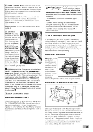 51
51 52
52 53
53 54
54 55
55 56
56 57
57 58
58 59
59 60
60 61
61 62
62 63
63 64
64 65
65 66
66 67
67 68
68 69
69 70
70 71
71 72
72 73
73 74
74 75
75 76
76 77
77 78
78 79
79 80
80 81
81 82
82 83
83 84
84 85
85 86
86 87
87 88
88 89
89 90
90 91
91 92
92 93
93 94
94 95
95 96
96 97
97 98
98 99
99 100
100 101
101 102
102 103
103 104
104 105
105 106
106 107
107 108
108 109
109 110
110 111
111 112
112 113
113 114
114 115
115 116
116 117
117 118
118 119
119 120
120 121
121 122
122 123
123 124
124 125
125 126
126 127
127 128
128 129
129 130
130 131
131 132
132 133
133 134
134 135
135 136
136 137
137 138
138 139
139 140
140 141
141 142
142 143
143 144
144 145
145 146
146 147
147 148
148 149
149 150
150 151
151 152
152 153
153 154
154 155
155 156
156 157
157 158
158 159
159 160
160 161
161 162
162 163
163 164
164 165
165 166
166 167
167 168
168 169
169 170
170