1988 FIAT TEMPRA power steering
[x] Cancel search: power steeringPage 10 of 171
• 9. DOOR MIRROR ADJUSTMENT
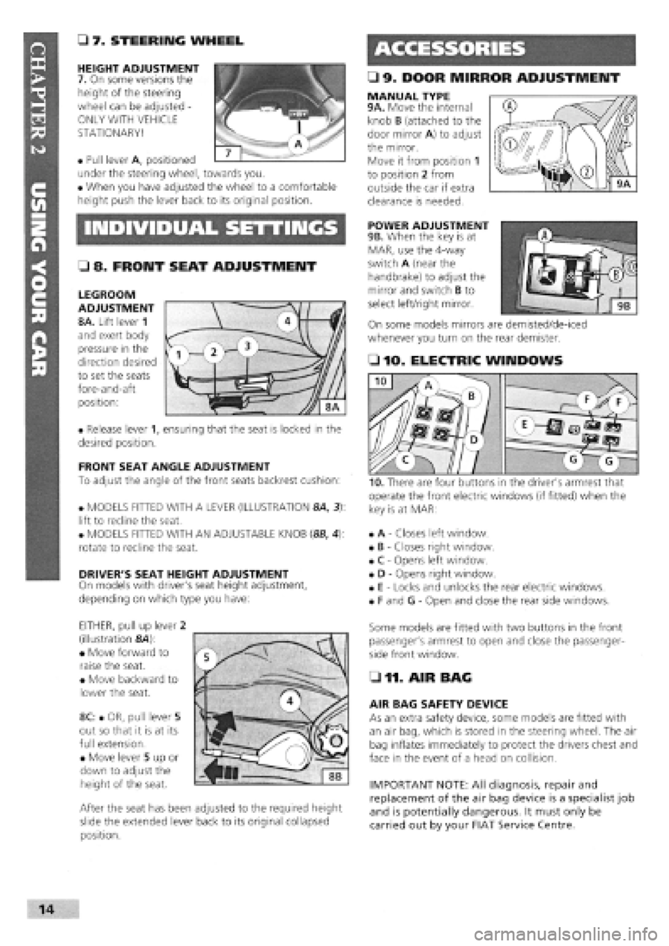
• 7. STEERING WHEEL
HEIGHT ADJUSTMENT
7. On some versions the
height of the steering
wheel can be adjusted -
ONLY WITH VEHICLE
STATIONARY!
• Pull lever A, positioned
under the steering wheel, towards you.
• When you have adjusted the wheel to a comfortable
height push the lever back to its original position.
MANUAL TYPE 9A. Move the internal
knob B (attached to the
door mirror A) to adjust
the mirror.
Move it from position 1
to position 2 from
outside the car if extra
clearance is needed.
INDIVIDUAL SETTINGS POWER ADJUSTMENT
9B. When the key is at
MAR, use the 4-way
switch A (near the
handbrake) to adjust the
mirror and switch B to
select left/right mirror.
On some models mirrors are demisted/de-iced
whenever you turn on the rear demister.
• 8. FRONT SEAT ADJUSTMENT
LEGROOM
ADJUSTMENT
8A. Lift lever 1
and exert body
pressure in the
direction desired
to set the seats
fore-and-aft
position:
• Release lever 1, ensuring that the seat is locked in the
desired position.
FRONT SEAT ANGLE ADJUSTMENT
To adjust the angle of the front seats backrest cushion:
• MODELS FITTED WITH A LEVER (ILLUSTRATION 8A, 3):
lift to recline the seat.
• MODELS FITTED WITH AN ADJUSTABLE KNOB (8B, 4):
rotate to recline the seat.
DRIVER'S SEAT HEIGHT ADJUSTMENT
On models with driver's seat height adjustment,
depending on which type you have:
EITHER, pull up lever 2
(illustration &4):
• Move forward to
raise the seat.
• Move backward to
lower the seat.
8C: • OR, pull lever 5
out so that it is at its
full extension.
• Move lever 5 up or
down to adjust the
height of the seat.
After the seat has been adjusted to the required height
slide the extended lever back to its original collapsed
position.
• 10. ELECTRIC WINDOWS
operate the front electric windows (if fitted) when the
key is at MAR:
• A
-
Closes left window.
• B
-
Closes right window.
• C
-
Opens left window.
• D
-
Opens right window.
• E
-
Locks and unlocks the rear electric windows.
• F and G
-
Open and close the rear side windows.
Some models are fitted with two buttons in the front
passenger's armrest to open and close the passenger-
side front window.
• 11. AIR BAG
AIR BAG SAFETY DEVICE
As an extra safety device, some models are fitted with
an air bag, which is stored in the steering wheel. The air
bag inflates immediately to protect the drivers chest and
face in the event of a head on collision.
IMPORTANT NOTE: All diagnosis, repair and
replacement of the air bag device is a specialist job
and is potentially dangerous. It must only be
carried out by your FIAT Service Centre.
I
Page 14 of 171

October 1991 2.0 i.e. 16v introduced, with 1995cc, 16 valve
high-performance DOHC engine, catalytic converter, sports
suspension, front and rear disc brakes. ABS available as
option.
January 1992 Existing Tipo models lightly facelifted and
redesignated 1.4 Formula, 1.45, 1.6S, 1.6SX, 1.9TD SX,
1.8 i.e. SX. 1.7D discontinued. SX versions with digital
instruments.
Tempra 1.9 TDS (turbo diesel) Station Wagon introduced. 1.4
and 1.9D saloons discontinued.
May 1992 Tempra 1.8 i.e. SX Saloon and Station Wagon
discontinued.
June 1992 Tempra 2.0 i.e. SX saloon and station wagon
models introduced, with high performance 1995cc DOHC fuel
injected engine, catalytic converter and disc brakes front and
rear.
Tipo 1.4 and all Tipo and Tempra 1.6 models (except Selecta)
now with a catalytic converter and fuel injection in place of
Weber twin-choke carburettor. Designated i.e. in badging.
December 1992 Tipo 1.8 i.e. and 1.6 Selecta discontinued.
February 1993 Tipo 2.0 i.e. GT introduced. Slightly lower
performance and spec, version of the 16v model.
July 1993 Tipo 1.4 now available as a 3-door or 5-door
hatchback. 2.0 i.e. 16v now only available as 3-door. Tipo 2.0
i.e. GT replaced by similar spec. 2.0 i.e. SLX.
Tempra 2.0 i.e. SX saloons and estates now only available
with auto, gearbox. Otherwise, SX models become known as
SLX, with colour-coded mirrors and ABS brakes. Most Tempras
now with body-coloured bumpers. 1.9D (non turbo Diesel re-
introduced).
All Tipo and Tempra models now with revised front-end
styling
-
narrower headlights and revised grille. Improved crash
protection, including side impact beams, safety steering wheel
and uprated brakes. Power steering, central locking, electric
windows all standard.
February 1994 Tipo 1.7 non-turbo diesel re-introduced as
1.7 DS.
May 1994 Tempra 1.9DS Station Wagon introduced.
September 1994 Most models available with driver's airbag,
fire prevention system and seat belt pre-tensioners.
December 1994 Tempra 1.6 i.e. versions get M.P.I, engine.
February/March 1995 All models with VIN number window
etching and immobiliser standard on all Tempra petrol models.
October 1995 Immobiliser fitted to Tempra D and TD models.
End of 1995 Tipo discontinued.
Mid-1996 Tempra discontinued.
PART B: VITAL STATISTICS
All Tipo models
-
55 litres, except petrol with catalytic converter
- 51
litres.
All Tempra models
-
65 litres, except petrol with catalytic converter
-
62 litres.
Wheels and Tyres
ENGINE PRESSED STEEL RADIAL TYRE PRESSURES (cold)
WHEEL RIM TYPE TUBELESS FRONT REAR
TYRE TYPE average load heavy load average load heavy load
TIPO MODELS
1.4 and 1.6 Petrol 5.00B x 13H 165/70R13S 2.0 bar/29 psi 2.0 bar/29 psi 1.9 bar/28 psi 2.2 bar/32 psi
1697 Diesel 5.00B x 13H 165/70R 13S 2.1 bar/30 psi 2.1 bar/30 psi 1.9 bar/28 psi 2.2 bar/32 psi
Turbo D 5.5J x 14H
175/65 R
14T 2.2 bar/32 psi 2.4 bar/35 psi 2.2 bar/32 psi 2.4 bar/35 psi
1.4 i.e./1.6 i.e. (1993-on) 5.5J x 14H
165/65 R
14T 2.0 bar/29 psi 2.0 bar/29 psi 1.9 bar/28 psi 2.2 bar/32 psi
1.7D (1993-on) 5.5J x 14H 165/65R 14T 2.1 bar/30 psi 2.1 bar/30 psi 1.9 bar/28 psi 2.2 bar/32 psi
Option
-
certain models 5.5J x 14AH2 185/60R 14H 2.2 bar/32 psi 2.4 bar/35 psi 2.2 bar/32 psi 2.4 bar/35 psi
TEMPRA MODELS
Early 1.4 and 1.6
Saloons 5.00B x 13H 165/70R 13S/T 2.0 bar/29 psi 2.0 bar/29 psi 2.0 bar/29 psi 2.2 bar/32 psi
1.6 SX Saloon 5.5J x 14H 165/65R 14T 2.0 bar/29 psi 2.0 bar/29 psi 2.0 bar/29 psi 2.2 bar/32 psi
1.9D/1.9 TD Saloon
and Late 1.6 i.e. 5.5J x 14H 175/65R 14T/H 2.2 bar/32 psi 2.4 bar/35 psi 2.2 bar/32 psi 2.4 bar/35 psi
1.6/1.9D/1.9TD
Station Wagons 5.5J x 14H 175/65R 14H 2.2 bar/32 psi 2.4 bar/35 psi 2.2 bar/32 psi 3.0 bar/44 psi
Option for Station 5.5J x 14H or AH2 185/60 R 14H 2.2 bar/32 psi 2.4 bar/35 psi 2.2 bar/32 psi 3.0 bar/44 psi
Wagons (alloy)
SPARE WHEEL
-
ALL TIPO AND TEMPRA MODELS (speed limit 50 mph)
Tempra TD Saloon and
ALL Station Wagons 4.00B x 14H 105/70 B14 4.2
bar/61
psi
All other models 4.00Bx14H 135/80 B14 2.8
bar/41
psi
Page 22 of 171

Handbrake Control
Screw with broad flange retaining handbrake and gear lever to body (M8)
Bolt retaining handbrake and gearlever to body (M8)
Screw with normal flange retaining handbrake lever bracket to plate (M8)
Screw with normal flange retaining handbrake cable slide plate to
floorpan (M6)
Screw with long flange for fastening handbrake cable reaction bracket to
floor (M8)
Screw with broad flange retaining pedal unit to dashboard (M8)
Self-locking nut for bolt retaining brake servo to pedal unit (M8)
Nut for through screw joining brake and clutch pedals to pedal unit (M8).
Self-locking nut retaining accelerator pedal to pedal unit (M6)
Nut retaining brake pump to brake servo (M8)
Steering
Self-locking nut retaining steering link ball pin to cast iron pillar (M10 x 1.25)..
Bolt retaining steering and/or power steering box to front beam (M10 x 1.25).
Nut for side steering link (M12 x 1.25)
Self-locking nut retaining steering shaft universal joint forks (M8)
Self-locking nut retaining steering wheel to column (M16 x 1.5)
Bolt retaining steering column mount to body (M6)
Self-locking nut for steering wheel position adjustment device (tighten nut
to specified torque with lever in locked position) (M12 x 1.25)
Nut for screw retaining steering column to support (M8)
Self-locking nut with polyamide ring retaining damper to steering box (M8)
Union for oil delivery fitting from pump to power steering, on power
steering (M14 x 1.5)
Union for adjustable oil delivery fitting from pump to p.s., on power
steering (M16 x 1.5)
Union for oil delivery fitting from power steering to reservoir (M12 x 1.5)
Union oil return fitting from reservoir to pump (M18 x 1.5)
Front Suspension
Screw with broad flange retaining front of front beam to body
(M12 x 1.25)
Screw with normal flange for nut retaining rear of front beam to body
(M10
x
1.25)
Screw with flat and tapered washer for nut retaining front and rear ext.
of wishbone connection plates to beam (M10 x 1.25)
Screws with flat and tapered washer for nut retaining front and rear inner
swinging arm connection plates to beam (M10 x 1.25)
Flanged nut fastening top of damper to block (M12 x 1.25)
Screw with broad flange retaining top damper block to body (M8)
Self-locking nut retaining damper to pillar (M10 x 1.25)
Self-locking nut for screw retaining wishbone head and joint to pillar
(M10
x
1.25)
Screw with tapered and flat safety washer retaining stabilizer bar
support plate to beam (M8)
Self-locking nut retaining end of anti-roll bar to rod (M10 x 1.25)
Self-locking nut retaining bar to front suspension arm (M10 x 1.25)
Nut retaining front wheel hub to coupling
(M22 x 1.5)i
(M24
x
1.5)
Wheel stud (M12 x 1.25).....
Rear Suspension
Screw with broad flange retaining front flexible block to rear subframe
(M12 x 1.25)
A B C D E Torque (Nm)
• • • • • 28
• • • • • 15
• • • • • 28
8.5
35
32
15
32
4.4
20 .
A B C D E Torque (Nm)
• • • • • 34
70
34
• • • • • 20
50
7.4
24
24
15
30
35
20
34
A B c D E Torque (Nm)
108
80
69
69
100
40
70
70
40
70
31
• • • • • •
24
28
86
A B c D E Torque (Nm)
108
Page 25 of 171

Windscreen and Mirrors
O 16. In zone 'A' of your windscreen, no items of damage larger than 10 mm in diameter will be allowed. In the rest of the area swept by the windscreen wipers, no damage greater than 40 mm in diameter will be allowed, nor should windscreen stickers or other obstructions encroach on this area.
o 17. Check that the exterior mirror on the driver's side is in good condition.
o 18. There must be one other mirror in good condition, either inside the car or an external mirror on the passenger's side.
Brakes
O 19. You cannot check the brakes
properly without a rolling road brake
tester but you can carry out the
following checks:
O 20. Pull on the handbrake. It should be fully ON before the handbrake reaches the end of its travel.
O 21. Knock the handbrake from side to side and check that it does not then release itself.
O 22. Check the security of the handbrake mountings and check the floor around it for rust or splits.
o 23. Check that the brake pedal is in good condition and that, when you take hold of it and move it from side to side, there is not too much play.
o 24. Push the footbrake down hard, with your foot. If it creeps slowly down to the floor, there is probably a problem with the master cylinder. Release the pedal, and after a few seconds, press down again. If the pedal feels spongy or it travels nearly to the floor, there is air in the system or another MoT-failing fault with the brakes.
o 25. Check the servo unit (when
fitted) as follows: Pump the pedal
several times then hold it down hard.
Start the engine. As the engine starts,
the pedal should move down slightly.
If it doesn't the servo or the vacuum
hose leading to it may be faulty.
Seat Belts and Seats
O 26. Examine all of the webbing (pull out the belts from the inertia reel if necessary) for cuts, fraying or deterioration.
o 27. Check that each inertia reel belt retracts correctly.
o 28. Fasten and unfasten each belt to ensure that the buckles work correctly.
o 29. Tug hard on each belt and inspect the mountings, as far as possible, to ensure that all are okay.
IMPORTANT NOTE: Checks apply to
rear seat belts as much as front
ones.
O 30. Make sure that the seat runners and mountings are secure and that the back rest locks in the upright position.
Doors and Door Locks
O 31. Check that both front doors latch securely when closed and that both can be opened and closed from both outside and inside the car.
PART B: VEHICLE ON THE GROUND
Electrical Equipment
See Part A: INSIDE THE CAR for checks on the operation of the electrical equipment.
O 1. Examine the wiper blades and replace those that show any damage.
Vehicle Identification
Numbers (VIIU)
O 2. The VIN (or chassis number on older vehicles) must be clearly displayed and legible.
O 3. Number plates must be secure, legible and in good condition with correct spacing between letters and numbers. Any non-standard spacing will not be accepted.
Braking System
O 4. Inside the engine bay inspect the master cylinder, servo unit (if fitted), brake pipes and mountings. Look for corrosion, loose fitting or leaks.
Steering and Suspension
OS . While still in the engine bay, have your assistant turn the steering wheel lightly from side to side and look for play in steering universal joints or steering rack mountings and any other steering connections.
OE. If your vehicle is fitted with power steering, check the security and condition of the steering pump, hoses and drivebelt, in the engine bay.
O 7. Look and reach under the car while your assistant turns the steering wheel more vigorously from side to side. Place your hand over each track rod end in turn and inspect all of the steering linkages, joints and attachments for wear.
o 8. Go around the vehicle and
'bounce' each corner of the
vehicle in turn. Release at the lowest
point and the vehicle should rise and
settle in its normal position without
continuing to 'bounce' of its own
accord.
Page 29 of 171

Thanks
are due to the excellent, knowledgeable and helpful staff at FIAT main dealers, Ryauto of Amblecote, in the West
Midlands for supplying vehicles and for their assistance with this chapter. In particular, thanks are due to the efficient Maurice
Hough, Service Manager, the experienced Foreman, Tony Morris, and young demon mechanic, Matthew Worsfold.
Some of the suggested inspection/replacement intervals may not correspond to those shown in the original handbook. The suggested
schedule, based on FIAT'S recommendations, takes into account the age of the vehicle and the annual MoT test in the UK.
In practice, because of the split between (mainly) 12 month/9,000 mile and 18 month/13,500 mile intervals, you will need to
service your Tipo or Tempra at most, if not every, 6 month interval.
IMPORTANT NOTE: Each service should be carried out at EITHER the recommended mileage OR the recommended time
interval, whichever comes first.
SERVICE INTERVAL CHART
SERVICE INTERVALS: KEY
A
-
Every week, or before every long journey. F
-
Every 3 years or 27,000 miles.
B
-
Every 6 months, or 4,500 miles. G
-
Every 4 years or 36,000 miles.
C - Every 12 months, or 9,000 miles. H
-
Every 6 years or 54,000 miles.
I
-
Every 63,000 miles. D - Every 18 months , or 13,500 miles.
H
-
Every 6 years or 54,000 miles.
I
-
Every 63,000 miles.
E
-
Every 2 years or 18,000 miles J
-
Every 72,000 miles.
PART A: REGULAR CHECKS
SERVICE INTERVALS
Job 1. Engine oil
-
check level A
Job 2. Cooling system
-
check level A
Job 3. Brake/clutch fluid
-
check level A
Job 4. Battery
-
check electrolyte level A
Job 5. Screen washer fluid
-
check level A
Job 6. Tyres
-
check pressures and
condition (road wheels) A
Job 7. Check lights/change bulbs A
PART B: THE ENGINE AND
COOLING SYSTEM
Job 8
-
Petrol. Change engine oil and filter C
Job 8
-
Diesel. Change engine oil and filter B
Job 9. Check crankcase ventilation H
Job 10. Check/adjust valve clearances D
Job 11. Check camshaft timing belt F
Job 12. Change camshaft timing belt I
Job 13. Check cooling system C
Job 14. Change engine coolant E
PART C: TRANSMISSION
Job 15. Check manual gearbox oil level C
Job 16. Change manual gearbox oil J
Job 17. Check auto, transmission fluid level C
Job 18. Change auto, transmission
fluid and filter F
Job 19. Check driveshaft gaiters C
Job 20. Check/adjust clutch C
Job 21. Check auto, transmission selector
cable E
PART D: IGNITION AND ELECTRICS
SERVICE INTERVALS
Job 22. Check/clean/gap spark plugs B
Job 23. Change spark plugs D
Job 24. Check/clean HT leads and
distributor cap C
Job 25. Check ignition timing C
Job 26. Check/adjust drive belt/s D
Job 27. Check electric fan operation C
Job 28. Run diagnostic ignition/injection test D
PART E: FUEL AND EXHAUST
Job 29. Check fuel pipes for leaks C
Job 30. Change petrol air filter D
Job 31. Change diesel air filter C
Job 32. Change petrol fuel filter F
Job 33. Drain diesel fuel filter B
Job 34. Change diesel fuel filter C
Job 35. Check/adjust petrol engine idle
and emissions C
Job 36. Check emission/evaporative/EGR systems F
Job 37. Check Lambda sensor F
Job 38. Check/adjust diesel idle speed C
Job 39. Check/adjust diesel injection timing E
Job 40. Check inlet and exhaust manifold fixings D
Job 41. Check exhaust system C
PART F: STEERING AND
SUSPENSION
Job 42. Check front wheel bearings C
Job 43. Check front suspension C
Job 44. Check steering column, joints and rack C
Job 45. Check power steering fluid C
Job 46. Check rear wheel bearings C
Job 47. Check rear suspension C
Job 48. Check wheel bolts for tightness C
Page 36 of 171

LUGGAGE COMPARTMENT LIGHT
7b. TIPO: Pull the lens
downwards to remove
it. Remove and replace
the 5W tubular bulb.
7c. TEMPRA SALOON:
From inside the boot,
lever the light unit out
of its slot with a screw-
driver. Remove and
replace the 5W tubular
bulb (A).
DASH BULBS
See Chapter 6, Repairs and Replacements for details of
instrument panel removal for access to its light bulbs. The
bulbs are a quarter-turn fit in the back of the panel.
FACT FILE: FUSES
• 7d. The fuse box is
found to the side of
the steering column.
Pull the lever
marked FUSE...
• ...and lower the fuse box.
• 7e. A symbol above each fuse tells you which circuit it
protects. Four spare fuses are located near the top of the
fuse box.
10A Instrument power supply, windscreen
washer pump, rear screen washer pump,
reverse lights, steering column switch lights,
FIAT CODE system.
10A Instrument power supply, left tail light,
right number plate light, right side light, left
trailer tail light.
10A Illumination of controls, right tail light,
left number plate light, right tail light.
20A Horns, cigarette lighter, stop lights.
20A Power locks.
7.5A Interior lighting.
20A Rear window heater and indicator light,
door mirror defogging elements (if fitted).
10A Hazard warning lights.
25A Electrical fan for radiator cooling (only
for petrol versions without air conditioner).
7.5A Direction indicators, right door power
mirror (if fitted).
7.5A Rear fog-guard lights and panel
indicator.
20A Front fog lights and panel indicator
(if fitted).
10A Right low beam headlight.
10A Left low beam headlight.
SERVIZI SERVICES
iOO:
-00 r
Q
M
mp
o$
ID
ID
7e
10A Left high beam headlight and panel
indicator.
10A Right high beam headlight.
20A Windscreen wiper.
20A Read window wiper, power sunroof and
heated seat (if fitted).
20A Heater/ventilation fan.
Fuses located on the auxiliary panel
The fuses protecting special devices (options, features of
special versions or devices with high power require-
ments) are on an auxiliary panel to the side of the fuse
box under the dashboard. It is much easier to remove
and replace auxiliary panel fuses if you first remove the
oddment tray and moulding fastened by 5 screws. The
panel also houses a number of relays:
20A Intake manifold heater (petrol engines).
20A Diesel fuel filter heater (diesel and turbo diesel
engines).
20A Headlight washer pump.
25A Front power windows.
25A Rear power windows.
10A Antilock braking system.
7.5A Low beam headlight dimming system (for countries
where headlights always need to be on.)
30A Radiator fan (diesel versions).
40A Radiator fan (turbo diesel versions with heater).
60A Radiator fan (turbo diesel versions with air condi-
tioning).
The arrangement of the fuses on the auxiliary panel
varies with the number and type of devices present.
The amperage is clearly marked on each fuse. ALWAYS
replace a blown fuse with one of the correct amperage.
NEVER 'fix' a fault by using a fuse of a higher amperage,
nor 'bridge' a blown fuse
-
it could cause a fire!
7f. When a fuse is 'blown'
its conductor wire (A) has
a gap in it.
If a fuse blows, find out
why and put it right
before fitting a new fuse.
(7)
o m f (7) (7)
0 tJ 7f
Page 54 of 171
each track rod end (TRE). Also, look out for a split gaiter.
Replace the TRE if the gaiter is split, or it will rapidly fail.
E3 INSIDE INFORMATION: Try placing your hand over the
TRE as the steering is moved. If there are any signs of
wear, replace the TRE. Q
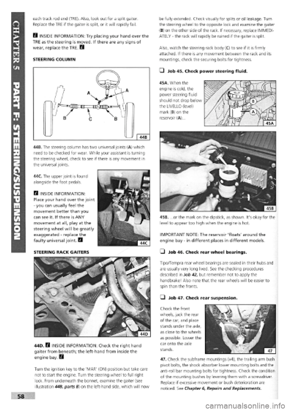
STEERING COLUMN
44B. The steering column has two universal joints (A) which
need to be checked for wear. While your assistant is turning
the steering wheel, check to see if there is any movement in
the universal joints.
44C. The upper joint is found
alongside the foot pedals.
Q INSIDE INFORMATION:
Place your hand over the joint
-
you can usually feel the
movement better than you
can see it. If there is ANY
movement at all, play at the
steering wheel will be greatly
exaggerated
-
replace the
faulty universal joint. B
STEERING RACK GAITERS
44D. B INSIDE INFORMATION: Check the right hand
gaiter from beneath; the left-hand from inside the
engine bay. Q
Turn the ignition key to the 'MAR' (ON) position but take care
not to start the engine. Turn the steering wheel to full right
lock. From underneath the bonnet, examine the gaiter (see
illustration 44B, parts B) on the left-hand side, which will now
be fully extended. Check visually for splits or oil leakage. Turn
the steering wheel to the opposite lock and examine the gaiter
(B) on the other side of the rack. If necessary, replace IMMEDI-
ATELY
-
the rack will rapidly be ruined if the gaiter is split.
Also, watch the steering rack body (C) to see if it is firmly
attached. If there is any movement between the rack and its
mountings, check the securing bolts for tightness.
• Job 45. Check power steering fluid.
45A. When the
engine is cold, the
power steering fluid
should not drop below
the LIVELLO (level)
mark (B) on the
reservoir (A)...
45B. ...or the mark on the dipstick, as shown. It's okay for the
level to appear too high when the engine is hot.
IMPORTANT NOTE: The reservoir 'floats' around the
engine bay
-
in different places in different models.
• Job 46. Check rear wheel bearings.
Tipo/Tempra rear wheel bearings are sealed in their hubs and
are usually very long lived. See the checking procedures
described in Job 42, but remember not to apply the
handbrake! Also note that the rear wheels will be easier to
spin than the fronts.
• Job 47. Check rear suspension.
Chock the front
wheels, jack the rear
of the car, and place
stands under the axle,
as close to the wheels
as possible. Lower the
car onto the axle
stands.
47. Check the subframe mountings (x4), the trailing arm bush
pivot bolts, the shock absorber lower mounting bolts and the
anti-roll bar mounting bolts for tightness. Check the condition
of the mounting bushes by levering them with a screwdriver.
Replace if excessive movement or bush deterioration are
noticed. See Chapter
6,
Repairs and Replacements.
Page 60 of 171

Please read the whole of CHAPTER
1,
SAFETY FIRST before carrying out any work on your car.
CHAPTER 6
REPAIRS AND REPLACEMENTS
This chapter shows you how
to remove and overhaul all
the major 'wearing' parts of
the car. We deliberately don't
show how to rebuild major
components, such as the
gearbox, or differential. You
are much better off, in terms
of time, cost and the
provision of a guarantee, to
buy a replacement unit.
The same applies to major
electrical components, such
as alternator and starter
motor. If, as we recommend,
you stick to 'original' FIAT
replacement parts, you will
maintain the original quality
of your car.
PART A: ENGINE
PART B: TRANSMISSION AND CLUTCH
PART C: COOLING SYSTEM
PART D: IGNITION
PART E: ELECTRICAL AND INSTRUMENTS
:er Contents
PARTf: FUEL AND EXHAUST
PART G: STEERING AND SUSPENSION
PART H: BRAKES
PART I: BODY AND INTERIOR
110
Page No.
116
127
134
143
Illustration and Section Numbers
• In this chapter, each area of the car is dealt with in a
different PART of the chapter, such as, PART A: ENGINE.
• Each job in each PART has a separate identifying number.
For example Job 2. Cylinder head removal.
• Every Job is broken down into easy-to-follow Steps,
numbered from 1-on.
• Illustrations are numbered so that you can see at a glance
where they belong!
• The illustration Job
1-3
(in PART A) for example, relates to
the text in Job 1, Step 3.
SAFETY FIRST!
• Before carrying out any of the work in this chapter,
be sure to read and understand Chapter 1, Safety
First!
• Be sure to read any safety notes supplied with any
of
the materials for equipment you purchase in
connection with the work described in this chapter.
• If you are not sure about your competence or
skills in
carrying out any of the work described in this chapter,
have the work carried out by your FIAT dealership.
FACT FILE: TIPO and TEMPRA ENGINE TYPES
PETROL ENGINES: The engines covered by
this manual are by far the most commonly
found in the UK. There may be the odd few with
different capacities or specifications which have been imported
from other countries but even they are usually similar. Here we
are concerned with one type of OHC (overhead camshaft)
PETROL engine, in 1372cc (1400) and 1581cc (1600) capacities.
They are best identified by the fact that the 1400 has its
distributor mounted on the side of the cylinder block and the
1600 has a distributor which is mounted on the end of the
camshaft, flywheel end.
DIESEL ENGINES: The Diesel engines covered here are the
1697cc (1700), the 1929cc (1900) and the 1929cc (1900) turbo.
It would take a trained eye to spot any differences between the
normally aspirated engines, but the turbo mounted on the
exhaust manifold together with its associated extra 'plumbing'
easily identifies the most powerful version.