1988 FIAT TEMPRA wheel bolts
[x] Cancel search: wheel boltsPage 12 of 171
EMERGENCY STARTING
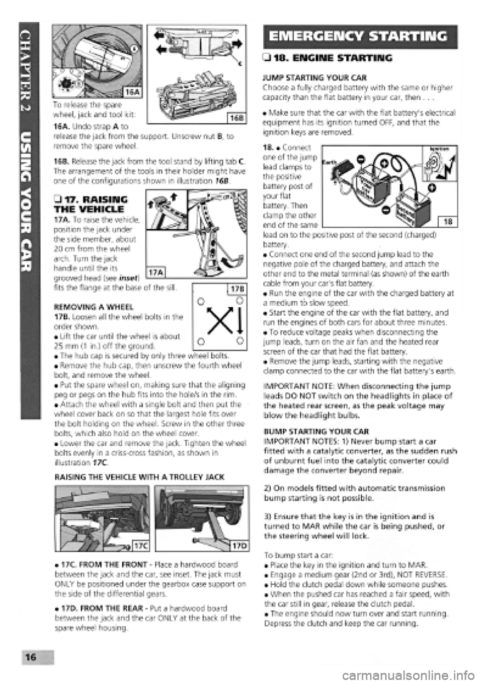
To release the spare
wheel, jack and tool kit:
16A. Undo strap A to
release the jack from the support. Unscrew nut B, to
remove the spare wheel.
16B. Release the jack from the tool stand by lifting tab C.
The arrangement of the tools in their holder might have
one of the configurations shown in illustration 16B.
• 17. RAISING
THE VEHICLE
17A. To raise the vehicle,
position the jack under
the side member, about
20 cm from the wheel
arch. Turn the jack
handle until the its
grooved head (see inset)
fits the flange at the base of the sill.
REMOVING A WHEEL
17B. Loosen all the wheel bolts in the
order shown.
• Lift the car until the wheel is about
25 mm
(1
in.) off the ground.
• The hub cap is secured by only three wheel bolts.
• Remove the hub cap, then unscrew the fourth wheel
bolt, and remove the wheel.
• Put the spare wheel on, making sure that the aligning
peg or pegs on the hub fits into the hole/s in the rim.
• Attach the wheel with a single bolt and then put the
wheel cover back on so that the largest hole fits over
the bolt holding on the wheel. Screw in the other three
bolts, which also hold on the wheel cover.
• Lower the car and remove the jack. Tighten the wheel
bolts evenly in a criss-cross fashion, as shown in
illustration 17C.
RAISING THE VEHICLE WITH A TROLLEY JACK
• 17C. FROM THE FRONT
-
Place a hardwood board
between the jack and the car, see inset. The jack must
ONLY be positioned under the gearbox case support on
the side of the differential gears.
• 17D. FROM THE REAR
-
Put a hardwood board
between the jack and the car ONLY at the back of the
spare wheel housing.
• 18. ENGINE STARTING
JUMP STARTING YOUR CAR
Choose a fully charged battery with the same or higher
capacity than the flat battery in your car, then ...
• Make sure that the car with the flat battery's electrical
equipment has its ignition turned OFF, and that the
ignition keys are removed.
18. • Connect
one of the jump
lead clamps to
the positive
battery post of
your flat
battery. Then
clamp the other
end of the same
lead on to the positive post of the second (charged)
battery.
• Connect one end of the second jump lead to the
negative pole of the charged battery, and attach the
other end to the metal terminal (as shown) of the earth
cable from your car's flat battery.
• Run the engine of the car with the charged battery at
a medium to slow speed.
• Start the engine of the car with the flat battery, and
run the engines of both cars for about three minutes.
• To reduce voltage peaks when disconnecting the
jump leads, turn on the air fan and the heated rear
screen of the car that had the flat battery.
• Remove the jump leads, starting with the negative
clamp connected to the car with the flat battery's earth.
IMPORTANT NOTE: When disconnecting the jump
leads DO NOT switch on the headlights in place of
the heated rear screen, as the peak voltage may
blow the headlight bulbs.
BUMP STARTING YOUR CAR
IMPORTANT NOTES: 1) Never bump start a car
fitted with a catalytic converter, as the sudden rush
of unburnt fuel into the catalytic converter could
damage the converter beyond repair.
2) On models fitted with automatic transmission
bump starting is not possible.
3) Ensure that the key is in the ignition and is
turned to MAR while the car is being pushed, or
the steering wheel will lock.
To bump start a car:
• Place the key in the ignition and turn to MAR.
• Engage a medium gear (2nd or 3rd), NOT REVERSE.
• Hold the clutch pedal down while someone pushes.
• When the pushed car has reached a fair speed, with
the car still in gear, release the clutch pedal.
• The engine should now turn over and start running.
Depress the clutch and keep the car running.
16
Page 19 of 171

PART F: TORQUE WRENCH SETTINGS
Key for engine types and sizes: A
-
1372cc; B
-
1581cc;
C
-
1697cc Diesel; D
-
1929cc Diesel; E
-
1929cc Turbo Diesel.
Engine
Screw retaining caps to crankcase (M10 x 1.25)
Screw retaining intermediate and central caps to crankcase (M12 x 1.25)...
Self-locking screw retaining front and rear caps to crankcase (M12 x 1.25)
Bolt, cylinder head to engine block (M10 x 1.25)
IMPORTANT NOTE: All torque settings shown in
Newton-meters (Nm). Bolt, nut or screw sizes in
brackets in left-hand column.
Bolt, cylinder head to engine block (M12 x 1.25)
Bolts, top to bottom cylinder head (M8)
Nut for connecting rod cap retaining bolt (M9 x 1)
Screw, connecting rod cap (M10 x 1)
Screw retaining engine vent to crankcase
(M8)
(M8)
Screw retaining front cover to crankcase
(MlOx 1.25)
(M8)
Bolt retaining rear cover (flywheel side) to crankcase (M6)
Nut retaining inlet and exhaust ducts to cylinder head
(M8)
(M8)
Screw, flywheel to crankshaft
(M10x 1.25)
(M12
x
1.25)
Lower belt cover retaining screw (M8)
Screw, damping flywheel to drive gear (M8)
Nut retaining auxiliary drive pulley to crankshaft (M20 x 1.25)
Screw retaining drive shaft to crankshaft (*) (M14 x 1.5 left)
Screw, timing gears
(M10x 1.25)
(M12x 1.25)
Belt tensioner retaining bolt
(M8)
(M10x 1.25)
Fixed belt tensioner retaining screw (M10 x 1.25)
Screw retaining auxiliary component driven gear (oil pump) (M10 x 1.25)
Nut for camshaft cap retaining stud (M8)
Nut retaining camshaft and air vacuum pump end mounts (M8)
Combustion prechamber retaining ring (M32 x 1.5)
Nut, injection pump stud (M8)
Screw, injection pump (M8)
Nut fastening flexible block to coolant pump case (M12 x 1.25)
Nut, injection pump gear (M12 x 1.75)
Screw retaining reaction bracket to oil filter support and injection pump (M8).
Top retaining screw or nut, oil filter support and injection pump (M12 x 1.25)
Lower retaining screw, oil filter support and injection pump (M10 x 1.25)
Complete injector (M24 x 2)
Glow plugs (M12 x 1.25)
Nuts retaining fuel delivery line to injection pump and injector (M12 x 1.25)...
Bolt, coolant pump to engine block (M8 x 1)
Bolt retaining cover and bracket to coolant pump case (M8)
Oil pressure switch (M14 x 1.5)
Coolant temperature sender unit
(M16 x 1.5 tapered)
(M18x 1.5 tapered)
Coolant temperature thermal switch (M16 x 1.5 tapered)
(*) The bolt need not be greased.
A B C D E Torque (Nm)
• • 80
• • • 113
• • • 113
• • 40
+
90 degrees
+ 90 deqrees
• • • 100
+
90 degrees
+ 90 deqrees
• • 28
• • 51
• • • 25 + 50 deqrees
• •
• • •
25
20
• • 50
25
• 10
• •
• • •
28
25
• •
• • •
83
142
• • 25
• • • 28
• • 155
• • • 190
• •
• • •
83
118
• •
• • •
25
44
• • • 44
• • 83
• • • 19
• • • 19
• • • 118
• • • 25
• • • 25
• • 80
• • • 49
• • • 29
• • • 98
• • • 71
• • • 55
• • • 15
• • • 29
• • • 25
• • • 23
32
• •
• • • 34
30
• • 30
expert22 fl/i* http://rutracker.org 23
Page 29 of 171

Thanks
are due to the excellent, knowledgeable and helpful staff at FIAT main dealers, Ryauto of Amblecote, in the West
Midlands for supplying vehicles and for their assistance with this chapter. In particular, thanks are due to the efficient Maurice
Hough, Service Manager, the experienced Foreman, Tony Morris, and young demon mechanic, Matthew Worsfold.
Some of the suggested inspection/replacement intervals may not correspond to those shown in the original handbook. The suggested
schedule, based on FIAT'S recommendations, takes into account the age of the vehicle and the annual MoT test in the UK.
In practice, because of the split between (mainly) 12 month/9,000 mile and 18 month/13,500 mile intervals, you will need to
service your Tipo or Tempra at most, if not every, 6 month interval.
IMPORTANT NOTE: Each service should be carried out at EITHER the recommended mileage OR the recommended time
interval, whichever comes first.
SERVICE INTERVAL CHART
SERVICE INTERVALS: KEY
A
-
Every week, or before every long journey. F
-
Every 3 years or 27,000 miles.
B
-
Every 6 months, or 4,500 miles. G
-
Every 4 years or 36,000 miles.
C - Every 12 months, or 9,000 miles. H
-
Every 6 years or 54,000 miles.
I
-
Every 63,000 miles. D - Every 18 months , or 13,500 miles.
H
-
Every 6 years or 54,000 miles.
I
-
Every 63,000 miles.
E
-
Every 2 years or 18,000 miles J
-
Every 72,000 miles.
PART A: REGULAR CHECKS
SERVICE INTERVALS
Job 1. Engine oil
-
check level A
Job 2. Cooling system
-
check level A
Job 3. Brake/clutch fluid
-
check level A
Job 4. Battery
-
check electrolyte level A
Job 5. Screen washer fluid
-
check level A
Job 6. Tyres
-
check pressures and
condition (road wheels) A
Job 7. Check lights/change bulbs A
PART B: THE ENGINE AND
COOLING SYSTEM
Job 8
-
Petrol. Change engine oil and filter C
Job 8
-
Diesel. Change engine oil and filter B
Job 9. Check crankcase ventilation H
Job 10. Check/adjust valve clearances D
Job 11. Check camshaft timing belt F
Job 12. Change camshaft timing belt I
Job 13. Check cooling system C
Job 14. Change engine coolant E
PART C: TRANSMISSION
Job 15. Check manual gearbox oil level C
Job 16. Change manual gearbox oil J
Job 17. Check auto, transmission fluid level C
Job 18. Change auto, transmission
fluid and filter F
Job 19. Check driveshaft gaiters C
Job 20. Check/adjust clutch C
Job 21. Check auto, transmission selector
cable E
PART D: IGNITION AND ELECTRICS
SERVICE INTERVALS
Job 22. Check/clean/gap spark plugs B
Job 23. Change spark plugs D
Job 24. Check/clean HT leads and
distributor cap C
Job 25. Check ignition timing C
Job 26. Check/adjust drive belt/s D
Job 27. Check electric fan operation C
Job 28. Run diagnostic ignition/injection test D
PART E: FUEL AND EXHAUST
Job 29. Check fuel pipes for leaks C
Job 30. Change petrol air filter D
Job 31. Change diesel air filter C
Job 32. Change petrol fuel filter F
Job 33. Drain diesel fuel filter B
Job 34. Change diesel fuel filter C
Job 35. Check/adjust petrol engine idle
and emissions C
Job 36. Check emission/evaporative/EGR systems F
Job 37. Check Lambda sensor F
Job 38. Check/adjust diesel idle speed C
Job 39. Check/adjust diesel injection timing E
Job 40. Check inlet and exhaust manifold fixings D
Job 41. Check exhaust system C
PART F: STEERING AND
SUSPENSION
Job 42. Check front wheel bearings C
Job 43. Check front suspension C
Job 44. Check steering column, joints and rack C
Job 45. Check power steering fluid C
Job 46. Check rear wheel bearings C
Job 47. Check rear suspension C
Job 48. Check wheel bolts for tightness C
Page 45 of 171

FACT FILE: DIGIPLEX DISTRIBUTOR
REMOVAL
25E. If the distributor has to be removed
for any reason, it is ESSENTIAL that the
PRECISE position of the rotor arm in
relation to the distributor body and the
position of the distributor body (2) in relation to the
cylinder head
-
via the spacer (1)
-
are clearly marked so
that they can be
replaced in
EXACTLY the
same position.
Note that the
locator
(arrowed) only
gives an approx-
imate, not a
precisely correct
location of the
spacer.
25F. D INSIDE
INFORMATION:
Use
touch-up
paint
and
let it
dry before
removing the
unit. D
SETTING THE RPM AND TDC SENSOR POSITION
25G. This job can not
be carried out without
the FIAT special tool
illustrated. The sensor
is correctly positioned
when the engine is
produced and to
prevent accidental
tampering, one of the
two bolts holding the
sensor in place is a
shear bolt and will have to be renewed if removed.
IMPORTANT NOTE: The slots in the distributor body are
NOT used to alter the advance setting, as on a conven-
tional distributor. This operation is carried out by the
position of the TDC sensor
-
see later.
CHECKING THE IGNITION ADVANCE can be carried out in an
approximate manner using the same method as described in
25C.
However, you must make sure that the following steps
are
taken:
•
the
vacuum pipe between the electronic control unit and
the
inlet manifold must remain connected and be in good
condition
-
neither blocked nor split.
•
the
engine must be at its normal operating temperature.
•
the
idle speed/mixture/CO adjustments must be correct
-
see Job 35.
•
with
the engine idling at between 800 and 900 rpm, the
mark on
the crankshaft pulley should be at approximately 12
degrees BTDC.
IMPORTANT NOTE: The only marks are for 0, 4 and 10
degrees BTDC, so you will have to make a guess at the
correct position for 12 degrees.
FACT FILE: TIMING MARKS
y-; • It appears that some earlier engines
H. j may be fitted with different types of
J timing marks. There might be a metal
pointer fitted to the timing belt cover.
Other engines may have their timing marks in the
flywheel housing, so that you need to take out a rectan-
gular rubber bung and look out for the fixed timing
mark on the flywheel housing and the timing settings
on
the flywheel itself.
• It always helps to paint all of the timing marks with
white paint or typists' correction fluid so that they are
easier to see when the timing light is operating.
1. Line up the mark on the crankshaft pulley with the 0
degrees (TDC) mark on the timing belt cover. See 25C.
2. Without moving the crankshaft from this position, undo the
screws holding the rpm and TDC sensor to the sensor carrier
plate. Fit the tool no. 1895898000 in place of the sensor.
Check that the flywheel pin or lug (3) must fit in the groove of
the tool and the bolts must tighten easily. If not, carry out the
following procedure:
3. Slacken the bolts securing the carrier plate behind the
sensor.
4. Move the plate so that the tool slips freely into the sensor's
hole and the bolts tighten easily.
5. Tighten the bolts holding the sensor carrier plate in place.
6. Remove the tool and refit the sensor.
ON BOTH TYPES: As the distributor is turned (clockwise to
advance, anti-clockwise to retard), the timing mark on the
flywheel will be seen to move relative to the pointers. Move
the distributor so the timing marks are aligned correctly, and
retighten the clamp nut or bolts.
• Job 26. Check/adjust drive belt/s.
26A. Depending on
your Tipo or Tempra
model, access to the
alternator belt and
adjustment fixings will
probably be possible
from the engine bay.
V-BELTS ONLY
Check the belt, and if there is any sign of cracking, 'polishing',
fraying or severe wear on the inner face, replace it. The belt
should deflect by about 10 mm when firm thumb pressure is
applied to the belt between the pulleys in the direction of the
arrow. Too little tension and the belt might slip; too much,
and belt and bearing wear will increase.
Page 54 of 171
each track rod end (TRE). Also, look out for a split gaiter.
Replace the TRE if the gaiter is split, or it will rapidly fail.
E3 INSIDE INFORMATION: Try placing your hand over the
TRE as the steering is moved. If there are any signs of
wear, replace the TRE. Q
STEERING COLUMN
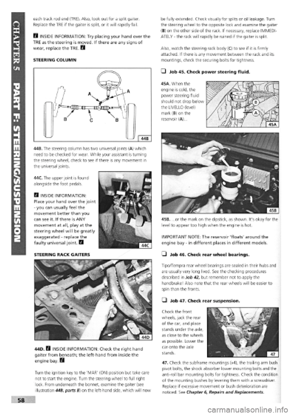
44B. The steering column has two universal joints (A) which
need to be checked for wear. While your assistant is turning
the steering wheel, check to see if there is any movement in
the universal joints.
44C. The upper joint is found
alongside the foot pedals.
Q INSIDE INFORMATION:
Place your hand over the joint
-
you can usually feel the
movement better than you
can see it. If there is ANY
movement at all, play at the
steering wheel will be greatly
exaggerated
-
replace the
faulty universal joint. B
STEERING RACK GAITERS
44D. B INSIDE INFORMATION: Check the right hand
gaiter from beneath; the left-hand from inside the
engine bay. Q
Turn the ignition key to the 'MAR' (ON) position but take care
not to start the engine. Turn the steering wheel to full right
lock. From underneath the bonnet, examine the gaiter (see
illustration 44B, parts B) on the left-hand side, which will now
be fully extended. Check visually for splits or oil leakage. Turn
the steering wheel to the opposite lock and examine the gaiter
(B) on the other side of the rack. If necessary, replace IMMEDI-
ATELY
-
the rack will rapidly be ruined if the gaiter is split.
Also, watch the steering rack body (C) to see if it is firmly
attached. If there is any movement between the rack and its
mountings, check the securing bolts for tightness.
• Job 45. Check power steering fluid.
45A. When the
engine is cold, the
power steering fluid
should not drop below
the LIVELLO (level)
mark (B) on the
reservoir (A)...
45B. ...or the mark on the dipstick, as shown. It's okay for the
level to appear too high when the engine is hot.
IMPORTANT NOTE: The reservoir 'floats' around the
engine bay
-
in different places in different models.
• Job 46. Check rear wheel bearings.
Tipo/Tempra rear wheel bearings are sealed in their hubs and
are usually very long lived. See the checking procedures
described in Job 42, but remember not to apply the
handbrake! Also note that the rear wheels will be easier to
spin than the fronts.
• Job 47. Check rear suspension.
Chock the front
wheels, jack the rear
of the car, and place
stands under the axle,
as close to the wheels
as possible. Lower the
car onto the axle
stands.
47. Check the subframe mountings (x4), the trailing arm bush
pivot bolts, the shock absorber lower mounting bolts and the
anti-roll bar mounting bolts for tightness. Check the condition
of the mounting bushes by levering them with a screwdriver.
Replace if excessive movement or bush deterioration are
noticed. See Chapter
6,
Repairs and Replacements.
Page 55 of 171

REAR SHOCK ABSORBERS • Job 48. Check wheel bolts for tightness.
Look for signs of leaks coming from underneath the top part
of
each
rear shock absorber and replace if necessary. Check
the
top and bottom rubber mounting bushes. If any are soft
or
split they must be replaced. Check that the bump stops are
present and correct.
BOUNCE TEST: Bounce-test the shock absorbers as in Job 43.
PART G: BRAKING SYSTEM
SAFETY FIRST!
• Job 49. Check front brakes.
You can
check the thickness of the brake pads by looking
through
the 'window' in the caliper. However, this isn't
recommended
unless you are experienced and know what you
are looking for,
and you can't check the caliper or clean out
accumulated
brake dust.
• Before raising the car, see Chapter 1, Safety First!
•
Also,
be sure to read the section on BRAKES AND
ASBESTOS in Chapter 1, Safety First! for further
important
information.
•
Your car's
brakes are its most important
safety-
related items.
Do NOT attempt any work on the
braking system unless
you are fully competent to do so.
• If you have not been trained in this work, but wish
to
carry
it out, we strongly recommend you have a
garage
or qualified mechanic check your work before
using
the car on the road.
•
Always
start by washing the brakes with a propri-
etary
brand of brake cleaner
-
brake drums removed
where
appropriate
-
and never use compressed air to
clean
off
brake
dust.
•
Always
replace brake pads and/or shoes in complete
'axle' sets
of four
-
never replace them on one wheel
only.
• After fitting new brake shoes or pads, avoid heavy
braking
for the first
150
to 200 miles (250 to 300 km),
except
in
an emergency.
49B. This
drawing
illustrates the
various
components of
the front brake
assembly.
49C. Remove the
bottom caliper bolt,
using an open-ended
spanner to allow the
bolt to turn. ALWAYS
refit with NEW FIAT
caliper mounting bolts
-
they are a special
type.
Therefore,
checking the Tipo's and Tempra's brake pads
involves
the same amount of work as changing them. For that
reason, brake
pad replacement is covered here in detail rather
than in
Chapter
6,
Repairs and Replacements.
49A. Start by raising
the
wheel to
be
worked on and
supporting it on
an
axle stand. Remove
the road wheel
-
see
Chapter
1, Safety
First!
Compare the thickness of the two pads
-
there should be no
significant difference. The minimum recommended thickness
of lining material is 1.5 mm, but bearing in mind the amount
of time before the next service, you may wish to replace the
pads before they get to this stage.
You can now check the thickness of the brake disc, which
should not be below the figure given for your model in
Chapter
3,
Facts and Figures, at any point.
Remove each wheel
bolt in turn and
ensure that they run
smoothly. Clean the
threads, if necessary.
Refit and check that all
are tightened to the
correct torque
-
see
Chapter
3,
Facts and
Figures
-
using a torque wrench.
49D. Slacken the top
bolt, swivel the caliper
up and the pads come
free, for checking.
IMPORTANT NOTE:
If you remove the
top caliper bolt, DO NOT allow the weight of the caliper
to hang from the flexible hose
-
position it to rest on the
driveshaft, or support it from the road spring using a
length of wire.
Page 56 of 171

49H. ...and push out the nylon bush (arrowed). Reassemble
on the new pad and reattach the wire.
IMPORTANT NOTE: After fitting the pads, apply the
brakes firmly several times to adjust them.
• Job 50. Check rear brakes.
SAFETY FIRST!
Read SAFETY FIRST at the start of Job 49 before
proceeding!
GENERAL. The majority of Tipo/Tempra models are fitted with
rear drum-type rear brakes, but models with ABS anti-lock
braking have a disc-and-caliper arrangement instead.
Slacken the wheel bolts, raise the wheel, remove it and
support the car with an axle stand. Make sure that the wheels
remaining on the ground are chocked in both directions and
that the handbrake is off.
DRUM REAR BRAKES
If the drum
sticks,
try:
• screwing a pair of
bolts
into the two threaded
holes in the drum. Evenly
tightening the bolts will force the drum off the
shoes.
• tapping carefully around the drum with a hide
mallet to help loosen it.
s Vn order to fit new pads,
r> - the caliper piston must be
pushed back into the bore.
• Use an old battery hydrometer to draw about half
of the fluid from the master cylinder.
• Push the piston back into the caliper, using a G-
clamp.
• Keep an eye on the master cylinder so that it
doesn't overflow as fluid is pushed back up the pipe.
IMPORTANT NOTE: Be very sparing or grease could
migrate to the friction linings!
WEAR SENSORS I I There are certain essential checks you
should carry out for yourself, with brake
pads removed:
• Look for any obvious grooves worn into the disc.
Slight undulations are acceptable, but anything worse
and the disc should be replaced.
• Look and feel for any wear-ridge on the outer edges
of the disc. The depth will give an indication of wear.
• Check for corrosion of the disc surface. If any is
found, the brake caliper is probably faulty, and needs
checking.
• If any surface flaking is found on either side of the
disc, replace them both.
• If you are not certain whether any wear is acceptable,
ask your specialist or FIAT dealer to check.
FACT FILE: BRAKE DISC WEAR
SYMPTOMS
Before reassembling the brake, check the condition of the
brake caliper. Have an assistant VERY SLOWLY AND GENTLY
apply pressure to the brake pedal while you watch the piston
(see illustration 49B, part
8),
which should move outwards. If
it doesn't easily move, it is seized and the caliper should be
replaced. DO NOT allow the piston to project more than 10
mm or it may be forced from the caliper
-
use a G-clamp as an
'end stop'.
49F. Before
fitting the pads,
put a light smear
of brake grease
(NOT ordinary
grease) on the
pads' metal
backplates at the
points shown.
49G. If these are fitted, the contact has to be transferred from
the old backing plate to the new. Pull off the wire, push out
the brass pin...
49E. Check inside
the caliper housing
for signs of
corrosion. If any is
found, or the seal is
damaged, the caliper
should be exchanged
for a new or
overhauled unit from
your FIAT dealership.
Examine the piston's protective gaiter (see illustration 49B,
part 9) for splitting and fluid leaks. This one is in poor
condition and the caliper requires immediate replacement.
Page 57 of 171
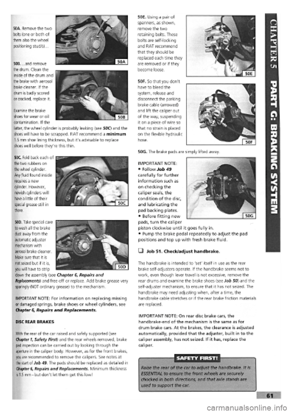
50A. Remove the two
bolts
(one or both of
them also the wheel
positioning stud/s)...
50B. ...and remove
the
drum.
Clean the
inside of the drum and
the brake with aerosol
brake
cleaner. If the
drum is badly scored
or cracked,
replace it.
50F. So that you don't
have to bleed the
system, release and
disconnect the parking
brake cable (arrowed)
and lift the caliper out
of the way, suspending
it on a piece of wire so
that no strain is placed
on the flexible hydraulic
hose.
50G. The brake pads are simply lifted away.
50E. Using a pair of
spanners, as shown,
remove the two
retaining bolts. These
bolts are self-locking
and FIAT recommend
that they should be
replaced each time they
are removed or if they
become loose.
Examine the brake
shoes
for wear or oil
contamination. If the
latter, the wheel cylinder is probably leaking (see 50C) and the
shoes will
have to be scrapped. FIAT recommend a minimum
1.5 mm
shoe lining thickness, but it's advisable to replace
shoes
well before they're this thin.
50C. Fold back each of
the
two rubbers on
the wheel
cylinder.
Any
fluid
found inside
requires a new
cylinder. However,
newish cylinders will
have a
little of their
special grease still in
there.
. """
€
Sjjj
KV,1
| 50D|
50D. Take
special care
to wash
all the brake
dust
away from the
automatic adjuster
mechanism with
aerosol brake cleaner.
Make
sure that it is
not seized
but if it is,
you will
have to strip
down
the assembly (see Chapter
6,
Repairs and
Replacements)
and free off or replace. Add brake grease very
sparingly (NOT ordinary grease) to the mechanism.
IMPORTANT NOTE: For information on replacing missing
or damaged springs, brake shoes or wheel cylinders, see
Chapter
6,
Repairs and Replacements.
DISC REAR BRAKES
With
the rear of the car raised and safely supported (see
Chapter 1,
Safety First) and the rear wheels removed, brake
pad
inspection can be carried out by looking through the
aperture in the caliper body. However, as for the front brakes,
you are
recommended to remove the calipers. See notes at
the
start of Job
49.
The pads should be replaced as detailed in
Chapter 6,
Repairs and Replacements. Minimum thickness
is 1.5 mm -
but don't let them get this low!
• Job 51. Check/adjust handbrake.
The handbrake is intended to 'set' itself in use as the rear
brake self-adjusters operate. If the handbrake seems not to
work, even though lever travel is not excessive, remove the
rear drums and examine the brake shoes (see Job 50) and the
self-adjuster mechanism, to ensure that it has not seized. The
handbrake may need adjusting when, after a time, the
handbrake cable stretches or if the rear brake friction materials
are replaced.
IMPORTANT NOTE: On rear disc brake cars, the
handbrake-end of the mechanism is the same as for
drum brake cars. At the brakes, the clearance is adjusted
automatically, provided that the adjuster, built in to the
caliper assembly, has not seized. If it has, replace the
caliper.
SAFETY FIRST!
Raise the rear of the car to adjust the handbrake. It
is
ESSENTIAL to ensure the front wheels are securely
chocked in both directions, and that axle stands are
used to support the car.
IMPORTANT NOTE:
• Follow Job 49
carefully for further
information such as
on checking the
caliper seals, the
condition of the disc,
and lubricating the
pad backing plates.
• Before fitting new
pads, turn the caliper
piston clockwise until it goes fully in.
• Pump the brake pedal repeatedly to adjust the pad
positions and top up with fresh brake fluid.