Page 129 of 171
 for the puller shaft to")
Job 13. Rear shock absorbers and
coil springs - replacement.
Q Step 12: ...then complete the
operation by using a standard
puller with a strong packing piece
(arrowed) for the puller shaft to
'push' against.
G Step 13: Remove the circlip
(see illustration Job
12-9,
part b)
and drift or press out the bearing
outer track from the hub carrier.
• Step 14: Check the hub
carrier for serviceability and
replace if it is in any way
damaged.
D INSIDE INFORMATION! The
new bearing is a complete
sealed unit and requires no
extra lubrication. D
• Step 15: Press the bearing
into the carrier using pressure on
the outer track ONLY (a). Fit the
circlip to retain it.
• Step 17:
Reassemble the front
suspension and brakes
in
the reverse order of
removal. See relevant
Jobs
for detailed infor-
mation. Use a NEW
hub nut fitted as
shown.
FACT FILE: STAKING THE HUB NUT
• Step 18: Use a cold
chisel
with an edge
ground to an angle of
about 60 degrees to stake
the
collar of the nut. USE
A
NEW NUT EACH TIME
IT IS REPLACED.
Q Step 19: Make sure the staked-down section of the collar
fits
in the stub axle
slot
in the opposite
direction to the
direction of the
nut
rotation, as
shown.
• Step 1: Refer to the drawings Job 1-1Cand 1-1D.
• Step 2: Leave the weight on the suspension by means of
a jack under the trailing arm (see illustration Job
1-1C,
part
• Step 3: Undo the nuts (see illustration Job
1-1D,
part
6)
and washers retaining the shock absorber (Job
1-1D,
part 5).
• Step 4: Pull the shock absorber off the top and bottom
mounting studs and carefully lower the jack to release the
pressure on, and then withdraw the coil spring. See also
Job 11
O Step 5: Refit in reverse order making sure that the coil
spring is properly seated top and bottom and that the shock
absorber nuts are tightened to the correct torque. See
Chapter
3,
Facts and Figures.
Job 14. Rear suspension and
wheel bearings - replacement.
Carry out this Job in connection with illustration Job
1-1C
and
1-1D.
• Step 1: IMPORTANT NOTE:
The trailing arms come
complete with bearings and
spacers (arrowed) as an
assembly. If the bearings are
defective, or the arm is cracked
or distorted, or showing signs
of wear or corrosion on the
wheel side, the whole assembly must be changed.
Q Step 2: Support the rear of the car on axle stands so that
the suspension hangs free. Remove the road wheels.
• Step 3: Remove the exhaust system. See PART F: FUEL
AND EXHAUST, Job 14.
• Step 4: Remove the fuel tank. See PART F: FUEL AND
EXHAUST, Job 10
• Step 5: Disconnect the brake pipes from the four-way
union and plug the ends to prevent excessive fluid loss.
Q Step 6: Slacken the cable adjustment under the
handbrake lever and disconnect the rear cable ends from the
equaliser. See PART H: BRAKES, Job 18
/ • Step 7: • Using a trolley
jack under the rear end of
the trailing arm to be
removed, compress the spring enough to undo the
mounting nuts and remove the shock absorber.
• Slowly lower the jack and remove the spring. This
allows you to use the weight of the car to help you
compress the spring
-
a difficult task otherwise!
Q Step 16: Press the hub into
the bearing, pushing ONLY on the
inner track with a suitable piece of
strong tube (1).
Page 130 of 171
.
Lower the
complete unit
from the car.
IMPORTANT NOTE: In")
• Step 8:
Support the
axle beam with
the jack and
undo the
mounting bolts
(arrowed and
indicated by
operator with
socket bar).
Lower the
complete unit
from the car.
IMPORTANT NOTE: In this shot, the top shock absorber
mountings have been disconnected, leaving the shock
absorber fitted to the suspension and the coil springs in
place. We recommend 'our' approach, covered in Step 7!
• Step 9: Undo the bolts securing the anti-roll bar and
remove it. (See Job 9.) Disconnect the brake pipes from the
side to be worked on and remove the brake drum.
Q Step 10: Remove the hub cap (see illustration Job 1-1D,
part 13) by carefully tapping and levering with a screwdriver.
• Step 11: Undo the hub nut (see illustration Job 1-1D,
part
10).
PART H: BRAKES
• Step 12: A special tool
(1857508000) or a VERY
strong Allen key (a) will be
required to reach into the
hub (b), and plenty of
leverage!
Q Step 13: Remove the
hub and inspect the bearing
for roughness or noise or
roughness when turning it by hand.
E3 INSIDE INFORMATION! The bearing is lubricated for
life and is only supplied as an assembly with the hub. B
• Step 14: Inspect the stub axle pin (see illustration Job
1-
1D, part
12)
for any signs of damage or distortion. Replace if
in doubt.
Q Step 15: Refitting is the reverse of removal but note the
following:
• See Chapter
3,
Facts and Figures for all tightening
torques as you progress through the assembling.
• Use new hub nuts and fully tighten once the suspension is
mounted to give you stability.
• Refer to PART H: BRAKES when refitting the brake parts
and bleeding the brakes.
PART H: Contents %
Job 1. Understanding Tipo/Tempra brakes.
Job 2. Front brake pads
-
replacement.
Job 3. Front brake caliper
-
replacement.
Job 4. Front brake disc
-
replacement.
Job 5. Rear brake shoes
-
replacement.
Job 6. Rear wheel cylinder
-
replacement.
Job 7. Rear brake disc pads
-
replacement.
Job 8. Rear brake caliper
-
replacement.
Job 9. Rear brake disc
-
replacement.
Job 10. Master cylinder
-
replacement.
Job 11. Servo check
-
remove and refit.
Job 12. Pressure regulating valve, non-ABS system -
replacement and adjustment.
Job 13. Pressure regulating valves, ABS system
-
replacement
and adjustment.
Job 14. RPM sensors, ABS systems
-
replacement.
Job 15. Flexible hoses
-
replacement.
Job 16. Metal pipes
-
replacement.
Job 17. Brake bleeding.
Job 18. Handbrake cables
-
replacement.
Job 1. Understanding
Tipo/Tempra brakes.
• Point
1
A: This is the standard disc/drum system used on
cars without anti-lock brakes, shown here in left hand drive
form.
1 - fluid reservoir and master cylinder 2 - servo 3
-
front disc brakes
4 - handbrake lever 5 - rear drum brakes 6
-
four way pipe union 7 - load proportioning/ pressure limiting valve
Job 1-1A
1 - front disc brakes 2
-
front flywheel 3 - front wheel RPM sensors 4 - hydraulic control unit 5 - brake light switch 6 - device failure warning light switch
7 - rear flywheel 8 - main control relay with excess voltage protection 9 - electronic control unit 10 - rear disc brakes 11 - rear wheel RPM sensors 12 - load proportioning/pressure limiting valve Job
1-1B
Page 131 of 171

Q Point 1B: This version shows the anti-lock braking system
and has discs replacing drums at the rear. One of two makes
is used
-
Lucas or Bosch
-
and both are similar in design.
Shown here is the Bosch ABS system in left hand drive form.
Apart from checking that the hydraulic and electrical connec-
tions are sound, anti-lock brakes are not repairable. Individual
components and friction materials can be replaced but
otherwise, you should consult your FIAT dealer for diagnosis
of system faults (with specialised equipment) and rectification.
SPECIAL NOTES: • Unplug the electronic control unit
(ECU) before any electric welding is carried out.
• When oven drying paint, the ECU cannot withstand 95
degrees Celsius for more than a few minutes or 85
degrees Celsius for more than 2 hours.
• Disconnect the battery earth before removing the
hydraulic control.
• When reconnecting the battery, make sure the connec-
tions are firm and sound.
Q INSIDE INFORMATION: When disconnecting brake
pipes or hoses, it is essential to minimise brake fluid loss.
This can be done by unscrewing the master cylinder
reservoir cap, laying a sheet of plastic across the opening,
and refitting the cap. This will prevent atmospheric
pressure from pushing the fluid out of opened lines. D
Job 2. Front brake pads -
replacement.
Changing and checking the Tipo's and Tempra's brake pads
are virtually identical jobs. See Chapter 5, Servicing Your
Car, pages 59 and 60
Job 3. Front brake caliper -
replacement.
Carry out this work with reference to Chapter 5, Servicing
Your Car, Job 49, pages 59 and 60.
Q Step 1: Slacken the front road wheels, jack up the car
and support on axle stands. Remove the wheels.
Q Step 2: Unplug
the brake pad wear
sensor (a
-
arrowed)
and ease the fluid
pipe/hose from the
bracket (b
-
arrowed)
on
the shock absorber
leg.
Q Step 3: Undo the brake fluid pipe union from the caliper
body and plug the end to prevent too much fluid loss.
Q Step 4: Undo the bolts and remove the caliper.
D INSIDE INFORMATION! The caliper securing bolts must
always be replace by new FIAT ones when loosened or
removed. They are of a special self-locking type. B
Q Step 5: Refit in reverse order and bleed the brakes, see
Job 17
Job 4. Front brake disc -
replacement.
Q Step 1: Carry out Steps 1 to 4 in Job 3.
• Step 2:
Undo the
securing bolts
and remove
the caliper
support
bracket.
• Step 3:
Undo the disc
fixing bolts
and withdraw
the brake
disc.
Q Step 4: Refit the remaining parts in reverse order of
removal. See Chapter 5, Servicing Your Car.
Carry out this work with reference to Chapter 5, Servicing
Your Car, Job 50, pages 60 and 61.
Job 5. Rear brake shoes -
replacement.
H INSIDE INFORMATION! It often helps to work on one
side at a time, completing all the work on that side of
the car and using the other side as a reference before
you start dismantling it. Q
• Before refitting the disc,
ensure that the mating
surfaces
-
hub to disc, are
clean and undamaged.
• Spin the disc to be sure there is no 'run out' before
proceeding further.
Job 4-2
Page 132 of 171

/ ''» prac^f step *ca"be
some FIAT mechanics prefer
to leave the cable disconnection until the brake shoes
are clear of the backplate.
Q Step 1: These are the brake shoe components and their
relative positions.
• Step 7: ...and
the self adjuster
return spring
followed by the
upper return spring
(arrowed).
• Step 8: Use a
pair of pliers to
push in and twist
the spring caps off
the shoe retaining
pins.
Q Step 11: The rear
shoe comes complete
with the adjuster.
• Step 3: Lever
out the cover from
the backplate to
expose the
handbrake cable
anchorage.
• Step 4:
THEORY! Using a
combination of
screwdriver and
long nosed pliers,
pull the cable nipple
until it is clear of
the step in the
anchorage and then
lift up the cable
nipple, while taking
• Step 9: Recover the caps
and springs and withdraw the
pins from the backplate.
• Step 10: Remove the brake
shoes and retrieve the return
springs.
1 - brake shoe 2 - brake shoe lower return spring 3 - brake shoe retaining pin/collet 4
-
self-adjusting device 5 - brake shoe upper return spring The arrow shows the washer/clip which has to be replaced each time the brake shoes are replaced -although they are often ready-fitted to the complete shoe adjuster assembly. Job 5-1
Job
5-8
Q Step 2: Remove the road wheel and brake drum, check
the wheel cylinder and use aerosol brake cleaner. See
Chapter 5,
Servicing Your
Car, Job 50
the pressure off the spring and allow it to
Job
5-11
come clear.
• Step 12: Release the self adjuster return spring from the
brake shoe and separate.
• Step 5: Take
the pressure off the
lower spring before
you try to remove
it. Lever the shoe
away from its lower
mounting point
(arrowed), pull it a
little way forwards, so that it slides over the front of the
mounting point and carefully release the tension.
• Step 6: Unhook and remove the lower return spring...
Page 133 of 171
 _ ^ Job 5_13
sparingly with
copper grease. Before refitting, reset th")
Job 8. Rear brake caliper -
replacement.
• Step 13:
Clean the
adjuster
assembly and
lubricate the
adjustment
screw (2) _ ^ Job 5_13
sparingly with
copper grease. Before refitting, reset the adjuster by screwing
the ratchet wheel (1) up to the spring (3) and then back off by
half a turn.
This job is carried out in the same way as pad replacement
{Job 7) with the addition of the following:
• Step 1:
Disconnect the
handbrake cable
(arrowed) and
withdraw from
the caliper body.
• Step 2: Slacken the brake
hose at the caliper end, undo
the caliper fixing bolts
(arrowed), remove the caliper
and unscrew the caliper and
flexible hose from the end of
the previously slackened rigid
hose. Plug the hose ends.
• Step 14: Smear a little brake grease (NOT ordinary
grease) very sparingly on all the shoe contact points on the
backplate and the springs, then continue to re-assemble in
reverse order. Refer to Job
18
for handbrake cable
adjustment.
• Step 15: Make
absolutely certain that all
of the springs are in good
condition (replace any
with stretched coils or
straightened ends) and are
fitted in their correct
locations.
Job 6. Rear wheel cylinder -
replacement.
Q Step 1: Refer to Job 5 and remove the brake shoes.
Q Step 2: Undo the brake pipe union at the back of the
wheel cylinder and plug the end (arrowed). Unscrew the two
fixing bolts and withdraw the cylinder.
Q Step 3: Refit in the reverse order of removal. Refer to Job
77
for brake bleeding.
• Step 3:
H INSIDE INFOR-
MATION! Before
fitting the new caliper
it must be primed with
new brake fluid by
connecting a tube to
the opened bleed
screw and pouring
brake fluid through it
until it comes out of
the hole where the brake hose fits (arrowed). Then lock
up the bleed nipple. Q
Q Step 4: Refit the caliper using NEW self locking bolts. See
Chapter 3, Facts and Figures
• Step 5: Complete this job as described in Chapter 5,
Servicing Your Car, Job 59, page 61.
Job 7. Rear brake disc pads
replacement.
Job 9. Rear brake disc
replacement.
Changing and checking the Tipo's and Tempra's brake pads
are virtually identical jobs. See Chapter 5, Servicing Your
Car, pages 60 and 61.
Q Step 1: Remove the brake pads and caliper as described
in
Job 7
and
8
• Step 2: Undo the mounting bolts (arrowed)...
Page 134 of 171

• Step 3: ...and
remove the caliper
support bracket.
Ll Step 4: Unscrew
the disc fixing bolts and
withdraw the disc.
clean and undamaged.
• Before refitting the disc,
ensure that the mating
surfaces
-
hub to disc, are
Job 10. Master cylinder
replacement.
H INSIDE INFORMATION: • On right-hand drive cars, the
master cylinder is on the driver's side and is VERY
different to get at, behind the engine.
• To remove the master cylinder on these cars you may
need to remove the complete assembly
-
master cylinder,
servo and pedal assembly
-
from inside the car. Q
• Step 1: IMPORTANT NOTE: Protect all paint surfaces
from possible brake fluid spillage before starting work.
You know what a good paint stripper it is!
• Step 2: Syphon off as much brake fluid as possible or
bleed it out
through one of the
front brakes until
the master cylinder
makes 'sucking'
noises.
• Step 3:
Remove the
reservoir from the
master cylinder.
138
• Step 4: Use a spanner
-
preferably a purpose-made split
ring spanner
-
to undo all the pipe unions from the master
cylinder.
• Step 5:
Undo the nuts
securing the
master cylinder
to the servo and
remove it.
• Step 6: Refit
in the reverse
order and refer
to Job
77
for
bleeding the
brakes.
Job 11. Servo check
and refit.
remove
Q INSIDE INFORMATION: • Before condemning the
servo for lack of efficiency, check the condition of the
one-way valve and vacuum pipe connecting it to the
inlet manifold.
• Ease the valve out of the front of the servo and
disconnect the pipe from the inlet manifold.
• Check that you can only blow one way through the
valve
-
from the servo end towards the inlet manifold (or
the brake vacuum pump
-
Diesel models).
• The vacuum pipe can suffer failure in many ways. Age
can harden it until it cracks, causing an air leak which
sometimes results in a whistling noise and rough slow-
running.
• Loose connections could also produce the same result.
• The other type of vacuum hose failure is an implosion
(where the hose is sucked flat by the vacuum) often
because oil has softened the hose.
• This is not so easily detected, as it rarely upsets the
engine performance and resumes its normal shape
shortly after the engine is stopped.
• The inner lining can also deteriorate, causing a
blockage. Q
• Step 1: Follow Job
10
to remove the master cylinder.
• Step 2: From inside the car, unhook the accelerator cable
from the pedal fork.
• Step 3:
Undo the
fixing nuts,
remove the
retaining
plate and
pedal
assembly.
•
eP^BH
1
| Mitx
IfP^K p{B||n (Or Hot
I
a^®. i kS^^^Ap
i
/is ^8*5211^3
in A
Mil
11 SaBPffe
l|i§
# J
Job 11-3
Page 135 of 171

Job 12. Pressure regulating valve,
non-ABS system - replacement
and adjustment.
• Step 9: Bleed the brakes, see Job
17
139
-8
The pressure regulating valve is also known as the load
proportioning valve.
[G Step 1: Position the car on ramps, over a pit or on a lift,
keeping the weight on the rear wheels.
• Step 2: Remove the handbrake cable from its support
bracket on the fuel tank...
• Step 3: ...and
remove the support
bracket for the rear
exhaust section for better
access.
• Step 4: Undo all the
pipe unions on the
regulating valve using
split ring spanners where
possible, to avoid
damage. Plug the ends
of the pipes and catch
any fluid that drains out.
Unhook the spring
(arrowed) from the
mounting bracket.
Q Step 5: Undo the fixing belts and remove the valve
assembly.
• Step 6: Mount the new unit, remake all hydraulic
connections and connect the spring. Note that, if the valve
does not work properly, it cannot be repaired but must be
replaced.
• Step 7: Place a load of 60 kg with a full fuel tank, or 90
kg with an empty fuel tank, as far forward as possible in the
boot.
• Step 4: Prise
off the sound
proofing plate
stud with a screw-
driver (1, which
cannot be re-
used) and
unscrew the stud
(2). Move the
plate (3) to one
side, to give
access to the
servo retaining
nuts.
• Step 5:
Remove the split
pin
and
disconnect the
servo rod from
the brake pedal.
G Step 6: Move
the sound
proofing plate
sufficiently to
remove the servo
mounting nuts
(three
-
arrowed;
one being
unscrewed by a
socket extension).
G Step 7: From
under the bonnet,
withdraw the
servo from the
bulkhead.
G Step 9: Adjust the nut as
necessary to achieve this
setting measuring through
the aperture in the front
cover, from inside the engine
bay.
G Step 10: Continue re-
assembly in reverse order.
G Step 8:
When refitting the
servo to the
bulkhead and
with the pushrod
(a) connected to
the brake pedal,
the gap between
the piston control
rod adjusting nut
(b) and the master
cylinder mounting
flange should be
between 22.45
and 22.65 mm.
22.45-22.65 mm
• Step 8:
• Loosen the
bracket
retaining screw
(1).
• Apply a
downwards
force to the
bracket eye (2)
of 55 Nm for all
models except
the 1600
automatic
petrol and 1900
turbo diesel which should be 30 Nm.
• Keeping the bracket (3) in position. Tighten the retaining
screw (1).
Page 136 of 171

Job 13. Pressure regulating
valves, ABS system - replacement
and adjustment.
Job 14. RPM sensors, ABS
systems - replacement.
H INSIDE INFORMATION! The RPM sensors align with
the flywheels (which look like toothed rings) and which
rotate with the road wheels. The sensors measure the
vehicle's running speed, acceleration, deceleration and
wheel creep. These signals are sent to the electronic
control unit and allow it to instruct the hydraulic control
unit to vary the brake fluid pressure to each wheel as
necessary to prevent the brakes from locking up. E3
• Step 1: This
is the position of
the front wheel
sensor (a)...
• Step 2: ...and
this is the position
of the rear wheel
sensor (arrowed).
H INSIDE INFORMATION! FIAT advise that no adjust-
ments can be made, so, if the gap is outside these values,
clean and check the condition and the seating of the
sensor and the condition of the flywheel. D
L_l Step 4: To remove the sensor, undo the fixing screw and
withdraw the sensor from its housing, then trace the wire to
the connector and unplug it.
• Step 5: Clean round the housing and fit the new sensor,
ensuring that it is properly seated.
O Step 6: Secure the wire along its route to the connector
and plug in.
• Step 1: Position the car over a pit or on a lift with the
weight still on the wheels. Locate the valves
-
one on each
suspension trailing arm.
• Step 2: Undo
the brake pipe
unions (a) using
(preferably) a split
ring spanner and
plug the ends of
the pipes. Remove
the two upper
securing bolts
shown here
• Step 3: Take out the
lower two bolts and
remove the valve.
• Step 4: Install the
new valve and connect
the brake pipes.
• Step 5: With the car
at its normal weight
including spare wheel
and fuel, add a load of 50
kg to the boot as far
forward as possible.
• Step 6:
• Loosen the
bracket fixing bolt
(1).
• Hang a weight
of 2 kg from the
bracket eye (2).
• Keep the
bracket in this
position while you
tighten and lock
the fixing bolt (1).
Q Step 7: Repeat this adjustment on the other side to
ensure equal braking.
• Step 8: Bleed the brakes. See Job
17
• Step 3:
Check the gap
between the end
of each sensor and the flywheel, at the front (see illustration
Job
14-1,
part b) and at the rear. The correct gap should be:
• 1400/1600 petrol
-
between 0.62 and 1.35 mm, both front
and rear.
• 1900 turbo Diesel
-
between 0.225 and 0.925 mm for the
fronts and between 0.13 and 1.27 mm for the rears.
 1
1 2
2 3
3 4
4 5
5 6
6 7
7 8
8 9
9 10
10 11
11 12
12 13
13 14
14 15
15 16
16 17
17 18
18 19
19 20
20 21
21 22
22 23
23 24
24 25
25 26
26 27
27 28
28 29
29 30
30 31
31 32
32 33
33 34
34 35
35 36
36 37
37 38
38 39
39 40
40 41
41 42
42 43
43 44
44 45
45 46
46 47
47 48
48 49
49 50
50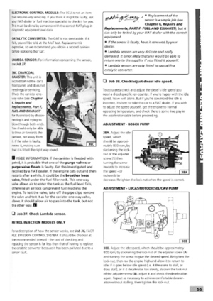 51
51 52
52 53
53 54
54 55
55 56
56 57
57 58
58 59
59 60
60 61
61 62
62 63
63 64
64 65
65 66
66 67
67 68
68 69
69 70
70 71
71 72
72 73
73 74
74 75
75 76
76 77
77 78
78 79
79 80
80 81
81 82
82 83
83 84
84 85
85 86
86 87
87 88
88 89
89 90
90 91
91 92
92 93
93 94
94 95
95 96
96 97
97 98
98 99
99 100
100 101
101 102
102 103
103 104
104 105
105 106
106 107
107 108
108 109
109 110
110 111
111 112
112 113
113 114
114 115
115 116
116 117
117 118
118 119
119 120
120 121
121 122
122 123
123 124
124 125
125 126
126 127
127 128
128 129
129 130
130 131
131 132
132 133
133 134
134 135
135 136
136 137
137 138
138 139
139 140
140 141
141 142
142 143
143 144
144 145
145 146
146 147
147 148
148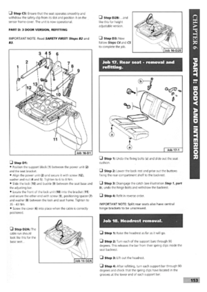 149
149 150
150 151
151 152
152 153
153 154
154 155
155 156
156 157
157 158
158 159
159 160
160 161
161 162
162 163
163 164
164 165
165 166
166 167
167 168
168 169
169 170
170