1988 FIAT TEMPRA torque
[x] Cancel search: torquePage 13 of 171
CHAPTER 3
FACTS ARID FIGURES
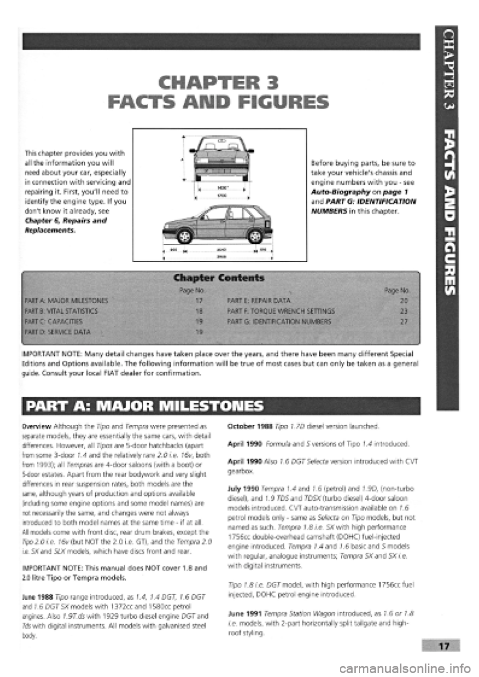
This chapter provides you with
all the information you will
need about your car, especially
in connection with servicing and
repairing it. First, you'll need to
identify the engine type. If you
don't know it already, see
Chapter 6, Repairs and
Replacements.
Before buying parts, be sure to
take your vehicle's chassis and
engine numbers with you
-
see
Auto-Biography on page 1
and PART G: IDENTIFICATION
NUMBERS in this chapter.
Chapter Contents
• -< Page No. Page No.
PART
A:
MAJOR MILESTONES 17 PART E: REPAIR DATA 20
PART
B:
VITAL STATISTICS 18 PART
F:
TORQUE WRENCH SETTINGS 23
PART C: CAPACITIES 19 PART G: IDENTIFICATION NUMBERS 27
PART
D:
SERVICE DATA 19
•
IMPORTANT NOTE: Many detail changes have taken place over the years, and there have been many different Special
Editions and Options available. The following information will be true of most cases but can only be taken as a general
guide. Consult your local FIAT dealer for confirmation.
PART A: MAJOR MILESTONES
Overview Although the Tipo and Tempra were presented as
separate models, they are essentially the same cars, with detail
differences. However, all Tipos are 5-door hatchbacks (apart
from some 3-door 1.4 and the relatively rare 2.0 i.e. 16v, both
from 1993); all Tempras are 4-door saloons (with a boot) or
5-door estates. Apart from the rear bodywork and very slight
differences in rear suspension rates, both models are the
same, although years of production and options available
(including some engine options and some model names) are
not necessarily the same, and changes were not always
introduced to both model names at the same time
-
if at all.
All models come with front disc, rear drum brakes, except the
Tipo
2.0 i.e. 16v (but NOT the 2.0 i.e. GT), and the Tempra 2.0
i.e. SXand SLX models, which have discs front and rear.
IMPORTANT NOTE: This manual does NOT cover 1.8 and
2.0 litre Tipo or Tempra models.
June 1988 Tipo range introduced, as 1.4, 1.4 DGT, 1.6 DGT
and 1.6 DGT SX models with 1372ccand 1580cc petrol
engines. Also 7.97".dswith 1929 turbo diesel engine DGT and
Ids with digital instruments. All models with galvanised steel
body.
October 1988 Tipo 1.7D diesel version launched.
April 1990 Formula and S versions of Tipo 1.4 introduced.
April 1990 Also 1.6 DGT Selecta version introduced with CVT
gearbox.
July 1990 Tempra 1.4 and 1.6 (petrol) and 1.9D, (non-turbo
diesel), and 1.9 TD5 and TD5X (turbo diesel) 4-door saloon
models introduced. CVT auto-transmission available on 1.6
petrol models only
-
same as Selecta on Tipo models, but not
named as such. Tempra 1.8 i.e. SX with high performance
1756cc double-overhead camshaft (DOHC) fuel-injected
engine introduced. Tempra 1.4 and 1.6 basic and 5 models
with regular, analogue instruments; Tempra SXand SX i.e.
with digital instruments.
Tipo 1.8 i.e. DGT model, with high performance 1756cc fuel
injected, DOHC petrol engine introduced.
June 1991 Tempra Station Wagon introduced, as 1.6 or 1.8
i.e. models, with 2-part horizontally split tailgate and high-
roof styling.
Page 19 of 171

PART F: TORQUE WRENCH SETTINGS
Key for engine types and sizes: A
-
1372cc; B
-
1581cc;
C
-
1697cc Diesel; D
-
1929cc Diesel; E
-
1929cc Turbo Diesel.
Engine
Screw retaining caps to crankcase (M10 x 1.25)
Screw retaining intermediate and central caps to crankcase (M12 x 1.25)...
Self-locking screw retaining front and rear caps to crankcase (M12 x 1.25)
Bolt, cylinder head to engine block (M10 x 1.25)
IMPORTANT NOTE: All torque settings shown in
Newton-meters (Nm). Bolt, nut or screw sizes in
brackets in left-hand column.
Bolt, cylinder head to engine block (M12 x 1.25)
Bolts, top to bottom cylinder head (M8)
Nut for connecting rod cap retaining bolt (M9 x 1)
Screw, connecting rod cap (M10 x 1)
Screw retaining engine vent to crankcase
(M8)
(M8)
Screw retaining front cover to crankcase
(MlOx 1.25)
(M8)
Bolt retaining rear cover (flywheel side) to crankcase (M6)
Nut retaining inlet and exhaust ducts to cylinder head
(M8)
(M8)
Screw, flywheel to crankshaft
(M10x 1.25)
(M12
x
1.25)
Lower belt cover retaining screw (M8)
Screw, damping flywheel to drive gear (M8)
Nut retaining auxiliary drive pulley to crankshaft (M20 x 1.25)
Screw retaining drive shaft to crankshaft (*) (M14 x 1.5 left)
Screw, timing gears
(M10x 1.25)
(M12x 1.25)
Belt tensioner retaining bolt
(M8)
(M10x 1.25)
Fixed belt tensioner retaining screw (M10 x 1.25)
Screw retaining auxiliary component driven gear (oil pump) (M10 x 1.25)
Nut for camshaft cap retaining stud (M8)
Nut retaining camshaft and air vacuum pump end mounts (M8)
Combustion prechamber retaining ring (M32 x 1.5)
Nut, injection pump stud (M8)
Screw, injection pump (M8)
Nut fastening flexible block to coolant pump case (M12 x 1.25)
Nut, injection pump gear (M12 x 1.75)
Screw retaining reaction bracket to oil filter support and injection pump (M8).
Top retaining screw or nut, oil filter support and injection pump (M12 x 1.25)
Lower retaining screw, oil filter support and injection pump (M10 x 1.25)
Complete injector (M24 x 2)
Glow plugs (M12 x 1.25)
Nuts retaining fuel delivery line to injection pump and injector (M12 x 1.25)...
Bolt, coolant pump to engine block (M8 x 1)
Bolt retaining cover and bracket to coolant pump case (M8)
Oil pressure switch (M14 x 1.5)
Coolant temperature sender unit
(M16 x 1.5 tapered)
(M18x 1.5 tapered)
Coolant temperature thermal switch (M16 x 1.5 tapered)
(*) The bolt need not be greased.
A B C D E Torque (Nm)
• • 80
• • • 113
• • • 113
• • 40
+
90 degrees
+ 90 deqrees
• • • 100
+
90 degrees
+ 90 deqrees
• • 28
• • 51
• • • 25 + 50 deqrees
• •
• • •
25
20
• • 50
25
• 10
• •
• • •
28
25
• •
• • •
83
142
• • 25
• • • 28
• • 155
• • • 190
• •
• • •
83
118
• •
• • •
25
44
• • • 44
• • 83
• • • 19
• • • 19
• • • 118
• • • 25
• • • 25
• • 80
• • • 49
• • • 29
• • • 98
• • • 71
• • • 55
• • • 15
• • • 29
• • • 25
• • • 23
32
• •
• • • 34
30
• • 30
expert22 fl/i* http://rutracker.org 23
Page 22 of 171

Handbrake Control
Screw with broad flange retaining handbrake and gear lever to body (M8)
Bolt retaining handbrake and gearlever to body (M8)
Screw with normal flange retaining handbrake lever bracket to plate (M8)
Screw with normal flange retaining handbrake cable slide plate to
floorpan (M6)
Screw with long flange for fastening handbrake cable reaction bracket to
floor (M8)
Screw with broad flange retaining pedal unit to dashboard (M8)
Self-locking nut for bolt retaining brake servo to pedal unit (M8)
Nut for through screw joining brake and clutch pedals to pedal unit (M8).
Self-locking nut retaining accelerator pedal to pedal unit (M6)
Nut retaining brake pump to brake servo (M8)
Steering
Self-locking nut retaining steering link ball pin to cast iron pillar (M10 x 1.25)..
Bolt retaining steering and/or power steering box to front beam (M10 x 1.25).
Nut for side steering link (M12 x 1.25)
Self-locking nut retaining steering shaft universal joint forks (M8)
Self-locking nut retaining steering wheel to column (M16 x 1.5)
Bolt retaining steering column mount to body (M6)
Self-locking nut for steering wheel position adjustment device (tighten nut
to specified torque with lever in locked position) (M12 x 1.25)
Nut for screw retaining steering column to support (M8)
Self-locking nut with polyamide ring retaining damper to steering box (M8)
Union for oil delivery fitting from pump to power steering, on power
steering (M14 x 1.5)
Union for adjustable oil delivery fitting from pump to p.s., on power
steering (M16 x 1.5)
Union for oil delivery fitting from power steering to reservoir (M12 x 1.5)
Union oil return fitting from reservoir to pump (M18 x 1.5)
Front Suspension
Screw with broad flange retaining front of front beam to body
(M12 x 1.25)
Screw with normal flange for nut retaining rear of front beam to body
(M10
x
1.25)
Screw with flat and tapered washer for nut retaining front and rear ext.
of wishbone connection plates to beam (M10 x 1.25)
Screws with flat and tapered washer for nut retaining front and rear inner
swinging arm connection plates to beam (M10 x 1.25)
Flanged nut fastening top of damper to block (M12 x 1.25)
Screw with broad flange retaining top damper block to body (M8)
Self-locking nut retaining damper to pillar (M10 x 1.25)
Self-locking nut for screw retaining wishbone head and joint to pillar
(M10
x
1.25)
Screw with tapered and flat safety washer retaining stabilizer bar
support plate to beam (M8)
Self-locking nut retaining end of anti-roll bar to rod (M10 x 1.25)
Self-locking nut retaining bar to front suspension arm (M10 x 1.25)
Nut retaining front wheel hub to coupling
(M22 x 1.5)i
(M24
x
1.5)
Wheel stud (M12 x 1.25).....
Rear Suspension
Screw with broad flange retaining front flexible block to rear subframe
(M12 x 1.25)
A B C D E Torque (Nm)
• • • • • 28
• • • • • 15
• • • • • 28
8.5
35
32
15
32
4.4
20 .
A B C D E Torque (Nm)
• • • • • 34
70
34
• • • • • 20
50
7.4
24
24
15
30
35
20
34
A B c D E Torque (Nm)
108
80
69
69
100
40
70
70
40
70
31
• • • • • •
24
28
86
A B c D E Torque (Nm)
108
Page 23 of 171
Screw with broad flange retaining rear flexible block to body (M12 x 1.25)..
Nut for stud retaining rear swinging arm to subframe (M16 x 1.5)
Nut for screw retaining lower damper to suspension (M12 x 1.25)
Screw retaining top of damper to mount (M10 x 1.25)
Nut for pivot pin retaining rear hub (M22 x 1.5)
Bolt retaining stabilizer bar to rear suspension arm (M10 x 1.25)
Bolt retaining stabilizer bar support plate to rear suspension arm (M8)
Wheel stud (M12 x 1.25)
Nut with self-locking flange retaining headlight alignment corrector
receiver to rear suspension (M8)
Nut with self-locking flange retaining lower receiver rod pin (M6)
Bolt with normal notched flange retaining automatic headlight
alignment device mount (M8)
Bolt with normal notched flange retaining receiver connection bracket with
rear suspension wishbone (M6)
Nut for bolt retaining square lever to wishbone (M8)
A B c D E Torque (Nm)
• • • • • 108
• • • • • 150
• • • • • 88
• • • • • 60
• • • • • 280
• • • • • 56
• • • • • 28
• • • • • 86
• • • • • 6.4
• • • • • 3.9
• • • • • 12
• • • • • 3.9
• • • • • 15
PART G: IDENTIFICATION NUMBERS
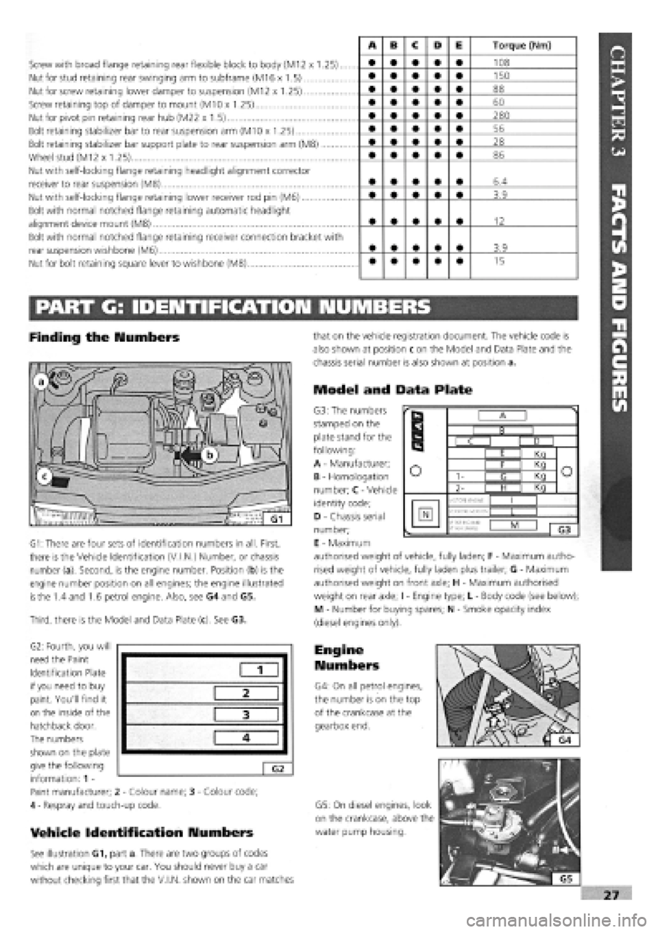
Finding the Numbers
G1: There are four sets of identification numbers in all. First,
there is the Vehicle Identification (V.I.N.) Number, or chassis
number (a). Second, is the engine number. Position (b) is the
engine number position on all engines; the engine illustrated
is
the 1.4 and 1.6 petrol engine. Also, see G4 and G5.
Third, there is the Model and Data Plate (c). See G3.
G2: Fourth, you will
need the Paint
Identification Plate
if you need to buy
paint. You'll find it
on the inside of the
hatchback door.
The numbers
shown on the plate
give the following
information: 1 -
Paint manufacturer; 2
-
Colour name; 3
-
Colour code;
4
-
Respray and touch-up code.
Vehicle Identification Numbers
See illustration G1, part a. There are two groups of codes
which are unique to your car. You should never buy a car
without checking first that the V.I.N, shown on the car matches
that on the vehicle registration document. The vehicle code is
also shown at position c on the Model and Data Plate and the
chassis serial number is also shown at position a.
Model and Data Plate
G3: The numbers
stamped on the
plate stand for the
following:
A
-
Manufacturer;
B
-
Homologation
number; C
-
Vehicle
identity code;
D
-
Chassis serial
number;
E
-
Maximum
authorised weight of vehicle, fully laden; F
-
Maximum autho-
rised weight of vehicle, fully laden plus trailer; G
-
Maximum
authorised weight on front axle; H
-
Maximum authorised
weight on rear axle; I
-
Engine type; L
-
Body code (see below);
M - Number for buying spares; N
-
Smoke opacity index
(diesel engines only).
Engine
Numbers
G4: On all petrol engines,
the number is on the top
of the crankcase at the
gearbox end.
G5: On diesel engines, look
on the crankcase, above the
water pump housing.
1
2
3
4
G2
r
B
r
B I B I
r
B
C I D I
r
B
I E I Kn
o o I F I Kq o o 1- I <3 I Kq o o
2- | H I Kq
o
MOTORE ENGINE
I I
N VERSIONE-VERSION •f
PER RICAM8:
N*
FOR SPARED
L I
1 G3
Page 41 of 171
IMPORTANT NOTE: Take care not to allow any dirt or grit
to get into the gearbox.
• Job 19. Check driveshaft gaiters.
45
B INSIDE INFORMATION: Make sure you have a 10 mm
Allen key that will fit, before you start. There's very little
room between gearbox and subframe. B
Q Job 17. Check auto, transmission fluid level.
The
automatic transmission fluid level should be checked with
the
car on level ground and the engine at normal running
temperature
-
the car should have been driven for about 4
miles. The level is checked by means of a dipstick next to the
battery.
IMPORTANT NOTE: i) It is especially important that the
fluid is at the correct level. If the system needs regular
topping up because of leaks, fix them as rapidly as
possible or have your FIAT dealer check the system,
ii) Wipe the dipstick only with a lint-free rag to avoid
clogging up transmission valves. Keep dirt out!
18B. The filter is
secured by one
central screw.
Undo this and pull
the filter down,
detaching its upper
fluid pipe in the
process. Remove
the filter, discard it
and fit the
replacement. Refit
the sump, using a
new gasket and
non-setting gasket
sealer.
Replace the drain plug and fill the gearbox through the
dipstick tube. {See Job
17.)
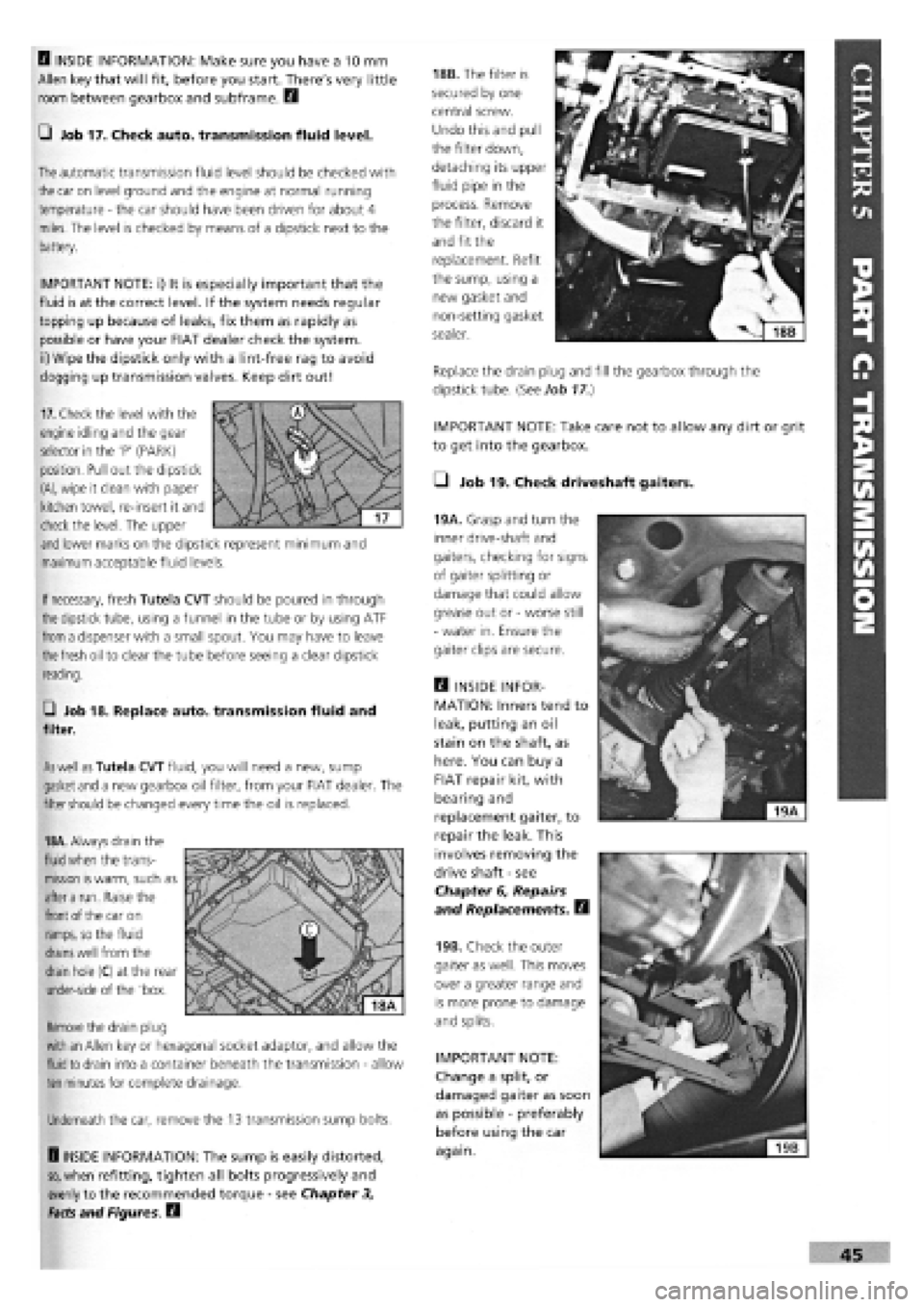
19A. Grasp and turn the
inner drive-shaft and
gaiters, checking for signs
of gaiter splitting or
damage that could allow
grease out or
-
worse still
-
water in. Ensure the
gaiter clips are secure.
Q INSIDE INFOR-
MATION: Inners tend to
leak, putting an oil
stain on the shaft, as
here. You can buy a
FIAT repair kit, with
bearing and
replacement gaiter, to
repair the leak. This
involves removing the
drive shaft
-
see
Chapter 6, Repairs
and Replacements. B
19B. Check the outer
gaiter as well. This moves
over a greater range and
is more prone to damage
and splits.
IMPORTANT NOTE:
Change a split, or
damaged gaiter as soon
as possible
-
preferably
before using the car
again.
If
necessary,
fresh Tutela CVT should be poured in through
the
dipstick tube, using a funnel in the tube or by using ATF
from
a dispenser with a small spout. You may have to leave
the fresh
oil to clear the tube before seeing a clear dipstick
reading.
G Job 18. Replace auto, transmission fluid and
filter.
As well as
Tutela CVT fluid, you will need a new, sump
gasket
and
a new gearbox oil filter, from your FIAT dealer. The
filter
should
be changed every time the oil is replaced.
18A.
Always drain the
fluid when
the trans-
mission
is
warm, such as
after a
run. Raise the
front
of the car on
ramps,
so the fluid
drains well
from the
drain
hole (C) at the rear
under-side of the 'box.
Remove
the drain plug
with an
Allen key or hexagonal socket adaptor, and allow the
fluid to
drain into a container beneath the transmission
-
allow
ten
minutes for complete drainage.
Underneath the car, remove the 13 transmission sump bolts.
H INSIDE INFORMATION: The sump is easily distorted,
so,
when refitting, tighten all bolts progressively and
evenly to the recommended torque
-
see Chapter 3,
Facts and Figures. B
17.
Check the level with the
engine idling and the gear
selector in the 'P' (PARK)
position. Pull out the dipstick
(A),
wipe it clean with paper
kitchen towel, re-insert it and
check the level. The upper
and
lower marks on the dipstick represent minimum and
maximum acceptable fluid levels.
Page 52 of 171
• Job 39. Check/adjust diesel injection timing.
Although a check of the injection timing is scheduled as a
service item, there is no reason why the timing should have
altered if the pump mounting bolts are tight and the pump
has not been disturbed. Injection timing is best checked
dynamically by a FIAT dealer or diesel specialist using
specialised equipment. If you want to check the timing stati-
cally, and you have access to a dial gauge and the necessary
adaptor to fit it to the pump, proceed as follows:
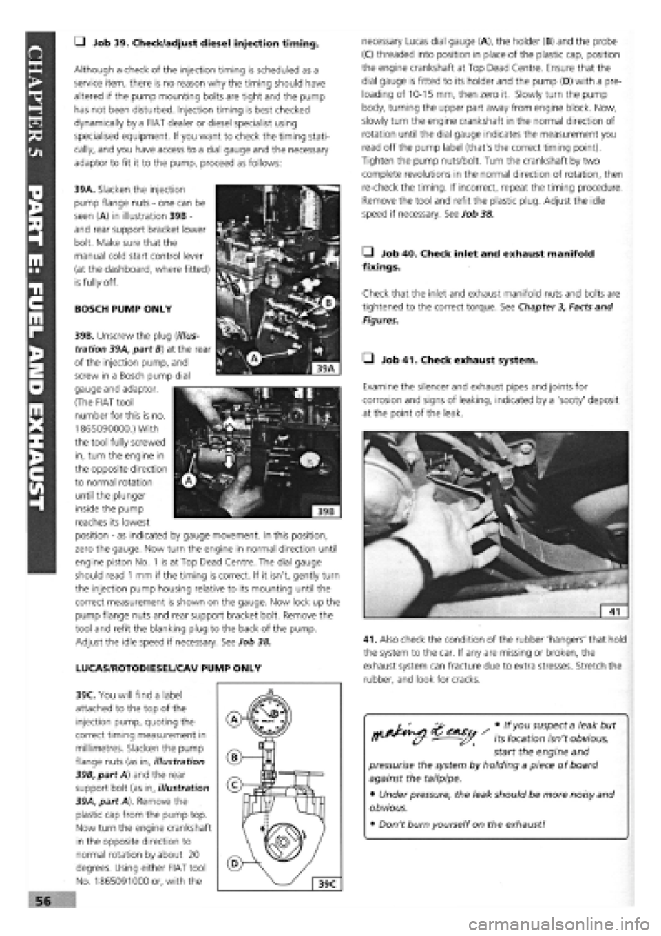
39A. Slacken the injection
pump flange nuts
-
one can be
seen (A) in illustration 39B -
and rear support bracket lower
bolt. Make sure that the
manual cold start control lever
(at the dashboard, where fitted)
is fully off.
BOSCH PUMP ONLY
necessary Lucas dial gauge (A), the holder (B) and the probe
(C) threaded into position in place of the plastic cap, position
the engine crankshaft at Top Dead Centre. Ensure that the
dial gauge is fitted to its holder and the pump (D) with a pre-
loading of 10-15 mm, then zero it. Slowly turn the pump
body, turning the upper part away from engine block. Now,
slowly turn the engine crankshaft in the normal direction of
rotation until the dial gauge indicates the measurement you
read off the pump label (that's the correct timing point).
Tighten the pump nuts/bolt. Turn the crankshaft by two
complete revolutions in the normal direction of rotation, then
re-check the timing. If incorrect, repeat the timing procedure.
Remove the tool and refit the plastic plug. Adjust the idle
speed if necessary. See Job 38.
• Job 40. Check inlet and exhaust manifold
fixings.
Check that the inlet and exhaust manifold nuts and bolts are
tightened to the correct torque. See Chapter
3,
Facts and
Figures.
• Job 41. Check exhaust system.
Examine the silencer and exhaust pipes and joints for
corrosion and signs of leaking, indicated by a 'sooty' deposit
at the point of the leak.
41. Also check the condition of the rubber 'hangers' that hold
the system to the car. If any are missing or broken, the
exhaust system can fracture due to extra stresses. Stretch the
rubber, and look for cracks.
39B. Unscrew the plug (illus-
tration 39A, part B) at the rear
of the injection pump, and
screw in a Bosch pump dial
gauge and adaptor.
(The FIAT tool
number for this is no.
1865090000.) With
the tool fully screwed
in, turn the engine in
the opposite direction
to normal rotation
until the plunger
inside the pump
reaches its lowest
position
-
as indicated by gauge movement. In this position,
zero the gauge. Now turn the engine in normal direction until
engine piston No. 1 is at Top Dead Centre. The dial gauge
should read
1
mm if the timing is correct. If it isn't, gently turn
the injection pump housing relative to its mounting until the
correct measurement is shown on the gauge. Now lock up the
pump flange nuts and rear support bracket bolt. Remove the
tool and refit the blanking plug to the back of the pump.
Adjust the idle speed if necessary. See Job 38.
LUCAS/ROTODIESEL/CAV PUMP ONLY
39C. You will find a label
attached to the top of the
injection pump, quoting the
correct timing measurement in
millimetres. Slacken the pump
flange nuts (as in, illustration
39B, part A) and the rear
support bolt (as in, illustration
39A, part A). Remove the
plastic cap from the pump top.
Now turn the engine crankshaft
in the opposite direction to
normal rotation by about 20
degrees. Using either FIAT tool
No. 1865091000 or, with the
cos / * susPect a but
fl^^^Cf- ^^ its location isn't obvious,
start the engine and
pressurise the system by holding a piece of board
against the tailpipe.
• Under pressure, the leak should be more noisy and
obvious.
• Don't burn yourself on the exhaust!
Page 55 of 171
REAR SHOCK ABSORBERS • Job 48. Check wheel bolts for tightness.
Look for signs of leaks coming from underneath the top part
of
each
rear shock absorber and replace if necessary. Check
the
top and bottom rubber mounting bushes. If any are soft
or
split they must be replaced. Check that the bump stops are
present and correct.
BOUNCE TEST: Bounce-test the shock absorbers as in Job 43.
PART G: BRAKING SYSTEM
SAFETY FIRST!
• Job 49. Check front brakes.
You can
check the thickness of the brake pads by looking
through
the 'window' in the caliper. However, this isn't
recommended
unless you are experienced and know what you
are looking for,
and you can't check the caliper or clean out
accumulated
brake dust.
• Before raising the car, see Chapter 1, Safety First!
•
Also,
be sure to read the section on BRAKES AND
ASBESTOS in Chapter 1, Safety First! for further
important
information.
•
Your car's
brakes are its most important
safety-
related items.
Do NOT attempt any work on the
braking system unless
you are fully competent to do so.
• If you have not been trained in this work, but wish
to
carry
it out, we strongly recommend you have a
garage
or qualified mechanic check your work before
using
the car on the road.
•
Always
start by washing the brakes with a propri-
etary
brand of brake cleaner
-
brake drums removed
where
appropriate
-
and never use compressed air to
clean
off
brake
dust.
•
Always
replace brake pads and/or shoes in complete
'axle' sets
of four
-
never replace them on one wheel
only.
• After fitting new brake shoes or pads, avoid heavy
braking
for the first
150
to 200 miles (250 to 300 km),
except
in
an emergency.
49B. This
drawing
illustrates the
various
components of
the front brake
assembly.
49C. Remove the
bottom caliper bolt,
using an open-ended
spanner to allow the
bolt to turn. ALWAYS
refit with NEW FIAT
caliper mounting bolts
-
they are a special
type.
Therefore,
checking the Tipo's and Tempra's brake pads
involves
the same amount of work as changing them. For that
reason, brake
pad replacement is covered here in detail rather
than in
Chapter
6,
Repairs and Replacements.
49A. Start by raising
the
wheel to
be
worked on and
supporting it on
an
axle stand. Remove
the road wheel
-
see
Chapter
1, Safety
First!
Compare the thickness of the two pads
-
there should be no
significant difference. The minimum recommended thickness
of lining material is 1.5 mm, but bearing in mind the amount
of time before the next service, you may wish to replace the
pads before they get to this stage.
You can now check the thickness of the brake disc, which
should not be below the figure given for your model in
Chapter
3,
Facts and Figures, at any point.
Remove each wheel
bolt in turn and
ensure that they run
smoothly. Clean the
threads, if necessary.
Refit and check that all
are tightened to the
correct torque
-
see
Chapter
3,
Facts and
Figures
-
using a torque wrench.
49D. Slacken the top
bolt, swivel the caliper
up and the pads come
free, for checking.
IMPORTANT NOTE:
If you remove the
top caliper bolt, DO NOT allow the weight of the caliper
to hang from the flexible hose
-
position it to rest on the
driveshaft, or support it from the road spring using a
length of wire.
Page 63 of 171

Job 2. Petrol engine. Cylinder
head • removal.
• Step 1: Take note of the parts shown in this drawing -
which is also relevant to several other jobs on Tipo and
Tempra petrol engines.
7
-
cirdip 8
-
plate 9
-
flywheel 10-spigot bearing
11 -
thrust bearing 12
-
main bearing 13-crankshaft
14 - sump 15 - sump gasket 16 - oil seal 17 - auxiliary shaft cover 18 - gasket 19 - front oil seal housing 20 - oil seal 21 - bush 22 - auxiliary shaft 23 - drive gear 24 - dipstick 25 - oil pump 26 - auxiliary shaft sprocket
1
-
piston 2
-
gudgeon pin 3
-
connecting rod 4
-
big-end bearing 5
-
big-end bolt 6
-
small-end bush
27 28 29 30 31 32 33 34 35 36 37 38 39
turbo 40 - exhaust manifold - turbo 41 - exhaust manifold - non-turbo 42 - heated air duct 43 - camshaft cover 44 - camshaft housing 45 - oil seal 46 - camshaft 47 - tappet shim 48 - oil seal 49 - tappet body 50
-
valve, top cap Job 2-1
- crankshaft sprocket - tensioner pulley - timing belt cover - camshaft sprocket - camshaft belt - bracket - end plate - cylinder head gasket - cylinder head - timing belt - rear cover - inlet manifolds - turbo - plenum chamber
-
turbo - inlet manifold - non-
51 - valve spring - inner 52 - valve spring
-
outer 53 - valve, top cap 54 - washer 55 - valve guide 56 - valve 57 - end plate 58 - rear oil seal housing 59 - block 60 - oil seal 61 - sump drain plug
Q INSIDE INFORMATION! • Before removing the
cylinder head, make sure the engine is stone cold.
• Undo the cylinder head bolts strictly in the order laid
out in Step 18.
• These precautions help to prevent cylinder head
distortion.
• The new cylinder head gasket should stay in its
packaging until required, to avoid contamination by oil
or grease.
B
FACT FILE: SPECIAL TOOL PROBLEMS
SOLVED!
• It is possible to remove and replace the
cylinder head complete with the camshaft
housing - but it is very difficult without
FIAT's special cranked tool to get round the camshaft
housing.
• You CAN undo the bolts with a ring spanner, but you
CAN'T torque them down properly again!
• Because the gasket between the housing and the head could
also be suspect, we strongly recommend that you do it 'our'
way, by removing the camshaft housing even though you will
have to re-set the valve clearances.