1988 FIAT TEMPRA suspension
[x] Cancel search: suspensionPage 13 of 171
CHAPTER 3
FACTS ARID FIGURES
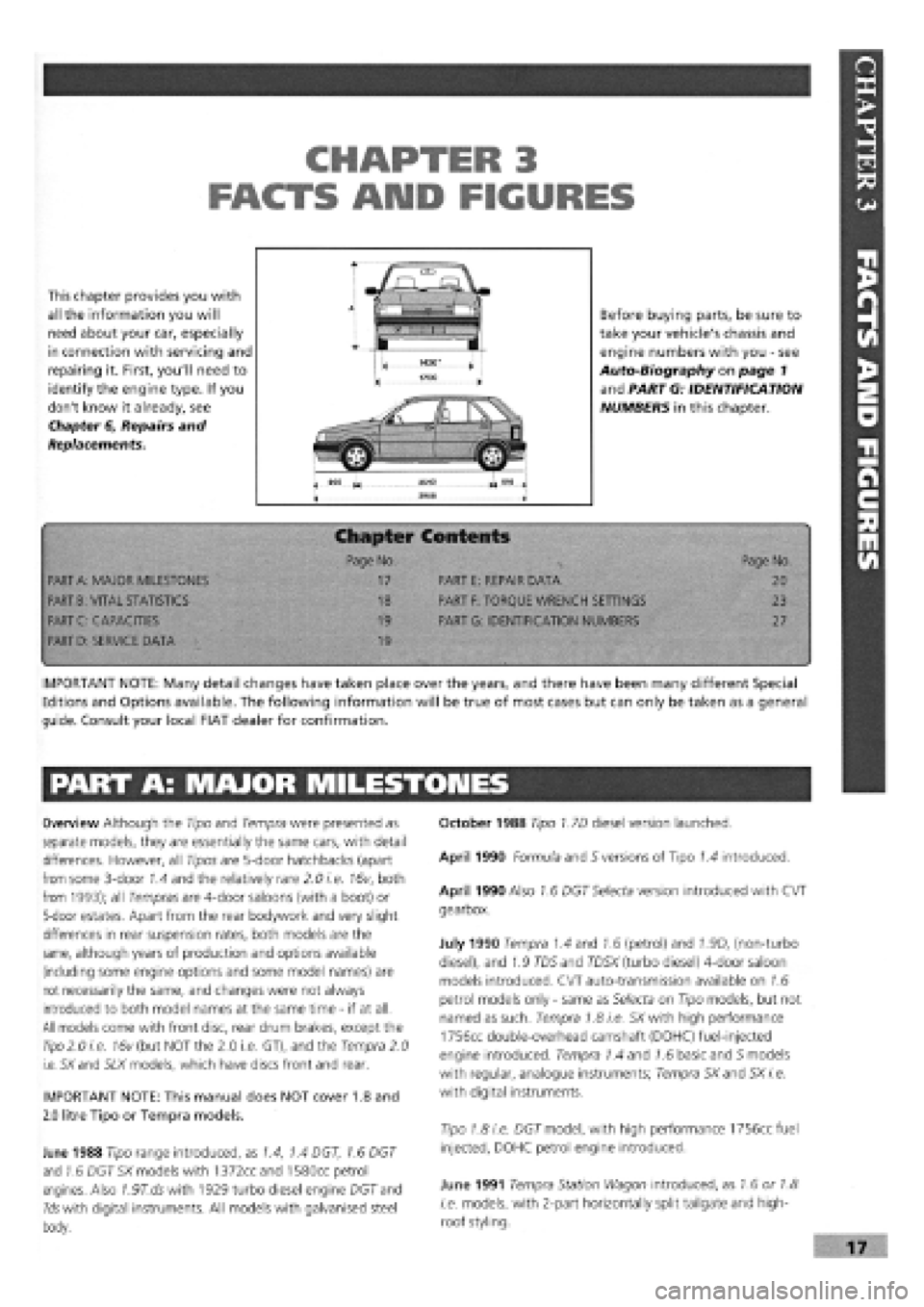
This chapter provides you with
all the information you will
need about your car, especially
in connection with servicing and
repairing it. First, you'll need to
identify the engine type. If you
don't know it already, see
Chapter 6, Repairs and
Replacements.
Before buying parts, be sure to
take your vehicle's chassis and
engine numbers with you
-
see
Auto-Biography on page 1
and PART G: IDENTIFICATION
NUMBERS in this chapter.
Chapter Contents
• -< Page No. Page No.
PART
A:
MAJOR MILESTONES 17 PART E: REPAIR DATA 20
PART
B:
VITAL STATISTICS 18 PART
F:
TORQUE WRENCH SETTINGS 23
PART C: CAPACITIES 19 PART G: IDENTIFICATION NUMBERS 27
PART
D:
SERVICE DATA 19
•
IMPORTANT NOTE: Many detail changes have taken place over the years, and there have been many different Special
Editions and Options available. The following information will be true of most cases but can only be taken as a general
guide. Consult your local FIAT dealer for confirmation.
PART A: MAJOR MILESTONES
Overview Although the Tipo and Tempra were presented as
separate models, they are essentially the same cars, with detail
differences. However, all Tipos are 5-door hatchbacks (apart
from some 3-door 1.4 and the relatively rare 2.0 i.e. 16v, both
from 1993); all Tempras are 4-door saloons (with a boot) or
5-door estates. Apart from the rear bodywork and very slight
differences in rear suspension rates, both models are the
same, although years of production and options available
(including some engine options and some model names) are
not necessarily the same, and changes were not always
introduced to both model names at the same time
-
if at all.
All models come with front disc, rear drum brakes, except the
Tipo
2.0 i.e. 16v (but NOT the 2.0 i.e. GT), and the Tempra 2.0
i.e. SXand SLX models, which have discs front and rear.
IMPORTANT NOTE: This manual does NOT cover 1.8 and
2.0 litre Tipo or Tempra models.
June 1988 Tipo range introduced, as 1.4, 1.4 DGT, 1.6 DGT
and 1.6 DGT SX models with 1372ccand 1580cc petrol
engines. Also 7.97".dswith 1929 turbo diesel engine DGT and
Ids with digital instruments. All models with galvanised steel
body.
October 1988 Tipo 1.7D diesel version launched.
April 1990 Formula and S versions of Tipo 1.4 introduced.
April 1990 Also 1.6 DGT Selecta version introduced with CVT
gearbox.
July 1990 Tempra 1.4 and 1.6 (petrol) and 1.9D, (non-turbo
diesel), and 1.9 TD5 and TD5X (turbo diesel) 4-door saloon
models introduced. CVT auto-transmission available on 1.6
petrol models only
-
same as Selecta on Tipo models, but not
named as such. Tempra 1.8 i.e. SX with high performance
1756cc double-overhead camshaft (DOHC) fuel-injected
engine introduced. Tempra 1.4 and 1.6 basic and 5 models
with regular, analogue instruments; Tempra SXand SX i.e.
with digital instruments.
Tipo 1.8 i.e. DGT model, with high performance 1756cc fuel
injected, DOHC petrol engine introduced.
June 1991 Tempra Station Wagon introduced, as 1.6 or 1.8
i.e. models, with 2-part horizontally split tailgate and high-
roof styling.
Page 14 of 171

October 1991 2.0 i.e. 16v introduced, with 1995cc, 16 valve
high-performance DOHC engine, catalytic converter, sports
suspension, front and rear disc brakes. ABS available as
option.
January 1992 Existing Tipo models lightly facelifted and
redesignated 1.4 Formula, 1.45, 1.6S, 1.6SX, 1.9TD SX,
1.8 i.e. SX. 1.7D discontinued. SX versions with digital
instruments.
Tempra 1.9 TDS (turbo diesel) Station Wagon introduced. 1.4
and 1.9D saloons discontinued.
May 1992 Tempra 1.8 i.e. SX Saloon and Station Wagon
discontinued.
June 1992 Tempra 2.0 i.e. SX saloon and station wagon
models introduced, with high performance 1995cc DOHC fuel
injected engine, catalytic converter and disc brakes front and
rear.
Tipo 1.4 and all Tipo and Tempra 1.6 models (except Selecta)
now with a catalytic converter and fuel injection in place of
Weber twin-choke carburettor. Designated i.e. in badging.
December 1992 Tipo 1.8 i.e. and 1.6 Selecta discontinued.
February 1993 Tipo 2.0 i.e. GT introduced. Slightly lower
performance and spec, version of the 16v model.
July 1993 Tipo 1.4 now available as a 3-door or 5-door
hatchback. 2.0 i.e. 16v now only available as 3-door. Tipo 2.0
i.e. GT replaced by similar spec. 2.0 i.e. SLX.
Tempra 2.0 i.e. SX saloons and estates now only available
with auto, gearbox. Otherwise, SX models become known as
SLX, with colour-coded mirrors and ABS brakes. Most Tempras
now with body-coloured bumpers. 1.9D (non turbo Diesel re-
introduced).
All Tipo and Tempra models now with revised front-end
styling
-
narrower headlights and revised grille. Improved crash
protection, including side impact beams, safety steering wheel
and uprated brakes. Power steering, central locking, electric
windows all standard.
February 1994 Tipo 1.7 non-turbo diesel re-introduced as
1.7 DS.
May 1994 Tempra 1.9DS Station Wagon introduced.
September 1994 Most models available with driver's airbag,
fire prevention system and seat belt pre-tensioners.
December 1994 Tempra 1.6 i.e. versions get M.P.I, engine.
February/March 1995 All models with VIN number window
etching and immobiliser standard on all Tempra petrol models.
October 1995 Immobiliser fitted to Tempra D and TD models.
End of 1995 Tipo discontinued.
Mid-1996 Tempra discontinued.
PART B: VITAL STATISTICS
All Tipo models
-
55 litres, except petrol with catalytic converter
- 51
litres.
All Tempra models
-
65 litres, except petrol with catalytic converter
-
62 litres.
Wheels and Tyres
ENGINE PRESSED STEEL RADIAL TYRE PRESSURES (cold)
WHEEL RIM TYPE TUBELESS FRONT REAR
TYRE TYPE average load heavy load average load heavy load
TIPO MODELS
1.4 and 1.6 Petrol 5.00B x 13H 165/70R13S 2.0 bar/29 psi 2.0 bar/29 psi 1.9 bar/28 psi 2.2 bar/32 psi
1697 Diesel 5.00B x 13H 165/70R 13S 2.1 bar/30 psi 2.1 bar/30 psi 1.9 bar/28 psi 2.2 bar/32 psi
Turbo D 5.5J x 14H
175/65 R
14T 2.2 bar/32 psi 2.4 bar/35 psi 2.2 bar/32 psi 2.4 bar/35 psi
1.4 i.e./1.6 i.e. (1993-on) 5.5J x 14H
165/65 R
14T 2.0 bar/29 psi 2.0 bar/29 psi 1.9 bar/28 psi 2.2 bar/32 psi
1.7D (1993-on) 5.5J x 14H 165/65R 14T 2.1 bar/30 psi 2.1 bar/30 psi 1.9 bar/28 psi 2.2 bar/32 psi
Option
-
certain models 5.5J x 14AH2 185/60R 14H 2.2 bar/32 psi 2.4 bar/35 psi 2.2 bar/32 psi 2.4 bar/35 psi
TEMPRA MODELS
Early 1.4 and 1.6
Saloons 5.00B x 13H 165/70R 13S/T 2.0 bar/29 psi 2.0 bar/29 psi 2.0 bar/29 psi 2.2 bar/32 psi
1.6 SX Saloon 5.5J x 14H 165/65R 14T 2.0 bar/29 psi 2.0 bar/29 psi 2.0 bar/29 psi 2.2 bar/32 psi
1.9D/1.9 TD Saloon
and Late 1.6 i.e. 5.5J x 14H 175/65R 14T/H 2.2 bar/32 psi 2.4 bar/35 psi 2.2 bar/32 psi 2.4 bar/35 psi
1.6/1.9D/1.9TD
Station Wagons 5.5J x 14H 175/65R 14H 2.2 bar/32 psi 2.4 bar/35 psi 2.2 bar/32 psi 3.0 bar/44 psi
Option for Station 5.5J x 14H or AH2 185/60 R 14H 2.2 bar/32 psi 2.4 bar/35 psi 2.2 bar/32 psi 3.0 bar/44 psi
Wagons (alloy)
SPARE WHEEL
-
ALL TIPO AND TEMPRA MODELS (speed limit 50 mph)
Tempra TD Saloon and
ALL Station Wagons 4.00B x 14H 105/70 B14 4.2
bar/61
psi
All other models 4.00Bx14H 135/80 B14 2.8
bar/41
psi
Page 18 of 171

1372 OHC 1580/1581 OHC 1697 Diesel 1929 D 1929 Turbo D
Brakes
GAP
-
SERVO PISTON PUSHROD FROM SUPPORT PLATE (d):
22.45-22.65 22.45-22.65 22.45-22.65
MINIMUM ALLOWED FRONT DISC THICKNESS (mm):
NON-ABS: 9.2 NON-ABS: 9.2 NON-ABS: 9.2
ABS: 10.2 ABS: 10.2
MINIMUM ALLOWED REAR DISC THICKNESS
-
when applicable
-
(mm):
9.2 9.2 9.2
MINIMUM ALLOWED BRAKE DRUM INTERNAL DIAMETER
-
when applicable
-
(mm):
181.35 A: 181.35
B: 230
Running gear/suspension - front
CAMBER (not adjustable):
-20' to 40' -20' to 40'
A: 181.35
B: 230
-20' to 40
22.45-22.65
10.2
ABS: 9.2
230
22.45-22.65
10.2
(TdsX: 10.8)
ABS: 9.2
230
-20' to 40' -20 to 40'
(TdsX: 25'
+/-
30')
FRONT CASTER (not adjustable):
1 degree 50'-2 degrees 50'
1
degree 50'-2 degrees 50'
1
degree 50'-2 degrees 50'
1
degree 50'-2 degrees 50' 1 degree 50'-2 degrees 50'
(TdsX: 2 degrees 50')
TOE-IN (adjustable)
-1
to
1
mm
-1
to
1
mm
-1
to
1
mm
-1
to
1
mm
FRONT SPRING HEIGHT RELEASED (mm):
432 EARLY: 432 461 EARLY: 489
TEMPRA: 444 LATE: 444 LATE: 472
TEMPRA: 489
FRONT SPRING: when the given load in Nm is applied, the spring height should equal 191 mm:
3020-3330 3020-3330 3310-3590 3600-3900
REPLACEMENT FRONT SPRING COLOURS: If new springs fail to give the above heights, YELLOW SPRINGS give LOWER heights;
GREEN springs give HIGHER. ALWAYS use them in pairs of same colour.
Rear suspension
CAMBER (not adjustable):
TOE-IN (not adjustable):
-1
to
1
mm
EARLY: 489
LATE: 472
TEMPRA: 493
3600-3900
-1 degree 30' to -30' -1 degree 30' to -30' -1 degree 30' to -30' -1 degree 30' to -30'
-3
to
1
mm
-3
to
1
mm
-3
to
1
mm -3 to
1
mm
-1 degree 30' to -30'
(TdsX: 1 degree 30' +/-15'
-3
to
1
mm
(TdsX:
-2
to 2 mm)
REAR COIL SPRING HEIGHT, RELEASED (mm):
3270 3270 3270 3270 3270
TEMPRA: 3390 TEMPRA: 3390 TEMPRA: 3390 TEMPRA: 3390
REAR COIL SPRING HEIGHT, LOAD in NM REQUIRED TO COMPRESS TO 195 mm.
2930-3170 2930-3170 2930-3170 2930-3170 2930-3170
TEMPRA: 3120-3380 TEMPRA: 3120-3380 TEMPRA: 3120-
3380 TEMPRA: 3120-3380
REPLACEMENT REAR SPRING COLOURS: If new springs fail to give the above heights, YELLOW springs give LOWER heights;
GREEN springs give HIGHER. ALWAYS use them in pairs of same colour.
(*) The bolt need not be greased
Page 20 of 171

Thermal valve on inlet manifold
(M10 x 1.25 tapered)
(M8 x 1.25 tapered)
Oil pressure sending unit (M14 x 1.5)
Oil temperature sender unit (M14 x 1.5 tapered)....
Oil level sending unit (M12 x 1.25)
Engine oil sump retaining bolt/nut (M6)
Screw retaining oil sealing cover to crankcase (M6)
Nut retaining manifold support bracket (M8)
Nut retaining turbine to exhaust manifold (M8)
Air pressure switch on inlet manifold (M12 x 1.5)...
Power Unit Mounting
ENGINE SIDE
Screw (with long flange) retaining flexible block to rail (M8)
Self-locking nut with plastic ring (for through screw) retaining flexible block
to engine bracket (M10 x 1.25)
Screw retaining flexible block supporting bracket to crankcase
(M10. 1.25)
(M12 x 1.25)
Bolt retaining flexible block to engine bracket (M12 x 1.25)
Bolt retaining power unit suspension link (M10 x 1.25)
GEARBOX SIDE
Screw (with wide flange) retaining flexible block to rail (M8)
Flanged screws retaining support to plate on gearbox (M10 x 1.25)
Self-locking nut with plastic ring (for through screw) retaining flexible block
to gearbox side bracket (M10 x 1.25)
Flanged screw retaining flexible block to gearbox side bracket (M12 x 1.25).
DIFFERENTIAL SIDE
Screw with flange unit retaining elastic block to beam (M8)
Self-locking nut retaining bracket to gearbox support
(M8)
(M12 x 1.25)
Screw retaining bracket brace to support on gear case (M10 x 1.25)
Screw, rubber block to bracket (M12 x 1.25)
Exhaust
Nut retaining flange to exhaust manifold (M8)
Nuts for bolts fastening collars joining exhaust pipe sections (M10 x 1.25)...
Bolt retaining exhaust pipe sleeve to turbine (M8)
Bolt retaining front exhaust pipe section to gearbox (M8)
Metex joint to nut and stud manifold to plate and spring retainer (M8)
Nut for bolt anchoring first exhaust pipe section (M8)
Nut retaining bracket anchoring first exhaust pipe section (M12 x 1.25)
Screw with normal flange retaining exhaust pipe terminal block
support bracket (M8)
Fuel Circuit
Bolt (with wide flange) retaining tank and fitting to body (M8)
Ring retaining delivery, recirculation and vent fitting mounts to tank
(131 x 6-Trapezoid thread)
Screw (with wide flange) retaining fuel filter support bracket (M8)
Page 21 of 171
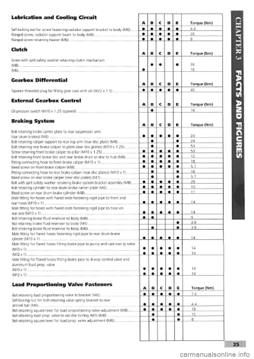
Lubrication and Cooling Circuit
Self-locking nut for screw fastening radiator support bracket to body (M6)....
Flanged screw, radiator support beam to body (M8)
Flanged screw retaining heater (M6)
Clutch
Screw with split safety washer retaining clutch mechanism
(M8)
(M6)
Gearbox Differential
Tapered threaded plug for filling gear case with oil (M22 x 1.5)
External Gearbox Control
Oil pressure switch (M10 x 1.25 tapered)
Braking System
Bolt retaining brake carrier plate to rear suspension arm
(rear drum brakes) (M8)
Bolt retaining caliper support to rear top arm (rear disc plate) (M8)
Bolt retaining rear brake caliper to plate (rear disc plates) (M10 x 1.25)
Screw retaining front brake caliper to pillar (M10 x 1.25)
Bolt retaining front brake disc and rear brake drum or disc to hub (M8)
Fitting connecting hose to front brake caliper (M10 x 1)
Bleed screw on front brake caliper (M8)
Fitting connecting hose to rear brake caliper (rear disc plates) (M10 x 1)
Bleed screw on rear brake caliper (rear disc plates) (M7)
Bolt with split safety washer retaining brake system bracket assembly (M8)....
Bolt retaining cylinder to rear drum brake carrier plate (M6)
Bleed screw on rear drum brake cylinder (M8)
Male fitting for hoses with flared ends fastening rigid pipe to front and
rear hoses (M10 x 1)
Male fitting for hoses with flared ends fastening rigid pipe to hose on
rear axle (M10 x 1)
Bolt retaining brake fluid reservoir to body (M8)
Nut retaining brake fluid reservoir to body (M6)
Bolt retaining brake fluid reservoir to body (M6)
Male fitting for flared hoses fastening rigid pipe to rear drum brake
cylinder
(M1
Ox 1)
Male fitting for flared hoses fitting brake pipe to pump and cast iron Ip valve
(M10
x
1)
(M12
x
1)
Male fitting for flared hoses fitting brake pipe to 4-way control valve and
aluminium load prop, valve
(M10 x
1)
(M12
x
1)
Load Proportioning Valve Fasteners
Bolt retaining load proportioning valve to bracket (M6)
Self-locking nut for bolt retaining valve spring bracket to rear
anti-roll bar (M6)
Bolt retaining square lever for load proportioning valve adjustment (M8)
Bolt retaining load prop, valve to rail (for Girling ABS) (M8)
Bolt retaining square lever for load prop, valve adjustment (M6)
Page 22 of 171

Handbrake Control
Screw with broad flange retaining handbrake and gear lever to body (M8)
Bolt retaining handbrake and gearlever to body (M8)
Screw with normal flange retaining handbrake lever bracket to plate (M8)
Screw with normal flange retaining handbrake cable slide plate to
floorpan (M6)
Screw with long flange for fastening handbrake cable reaction bracket to
floor (M8)
Screw with broad flange retaining pedal unit to dashboard (M8)
Self-locking nut for bolt retaining brake servo to pedal unit (M8)
Nut for through screw joining brake and clutch pedals to pedal unit (M8).
Self-locking nut retaining accelerator pedal to pedal unit (M6)
Nut retaining brake pump to brake servo (M8)
Steering
Self-locking nut retaining steering link ball pin to cast iron pillar (M10 x 1.25)..
Bolt retaining steering and/or power steering box to front beam (M10 x 1.25).
Nut for side steering link (M12 x 1.25)
Self-locking nut retaining steering shaft universal joint forks (M8)
Self-locking nut retaining steering wheel to column (M16 x 1.5)
Bolt retaining steering column mount to body (M6)
Self-locking nut for steering wheel position adjustment device (tighten nut
to specified torque with lever in locked position) (M12 x 1.25)
Nut for screw retaining steering column to support (M8)
Self-locking nut with polyamide ring retaining damper to steering box (M8)
Union for oil delivery fitting from pump to power steering, on power
steering (M14 x 1.5)
Union for adjustable oil delivery fitting from pump to p.s., on power
steering (M16 x 1.5)
Union for oil delivery fitting from power steering to reservoir (M12 x 1.5)
Union oil return fitting from reservoir to pump (M18 x 1.5)
Front Suspension
Screw with broad flange retaining front of front beam to body
(M12 x 1.25)
Screw with normal flange for nut retaining rear of front beam to body
(M10
x
1.25)
Screw with flat and tapered washer for nut retaining front and rear ext.
of wishbone connection plates to beam (M10 x 1.25)
Screws with flat and tapered washer for nut retaining front and rear inner
swinging arm connection plates to beam (M10 x 1.25)
Flanged nut fastening top of damper to block (M12 x 1.25)
Screw with broad flange retaining top damper block to body (M8)
Self-locking nut retaining damper to pillar (M10 x 1.25)
Self-locking nut for screw retaining wishbone head and joint to pillar
(M10
x
1.25)
Screw with tapered and flat safety washer retaining stabilizer bar
support plate to beam (M8)
Self-locking nut retaining end of anti-roll bar to rod (M10 x 1.25)
Self-locking nut retaining bar to front suspension arm (M10 x 1.25)
Nut retaining front wheel hub to coupling
(M22 x 1.5)i
(M24
x
1.5)
Wheel stud (M12 x 1.25).....
Rear Suspension
Screw with broad flange retaining front flexible block to rear subframe
(M12 x 1.25)
A B C D E Torque (Nm)
• • • • • 28
• • • • • 15
• • • • • 28
8.5
35
32
15
32
4.4
20 .
A B C D E Torque (Nm)
• • • • • 34
70
34
• • • • • 20
50
7.4
24
24
15
30
35
20
34
A B c D E Torque (Nm)
108
80
69
69
100
40
70
70
40
70
31
• • • • • •
24
28
86
A B c D E Torque (Nm)
108
Page 23 of 171
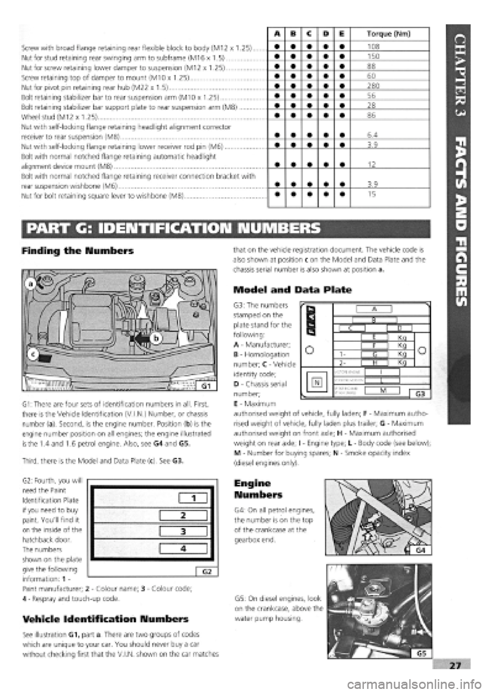
Screw with broad flange retaining rear flexible block to body (M12 x 1.25)..
Nut for stud retaining rear swinging arm to subframe (M16 x 1.5)
Nut for screw retaining lower damper to suspension (M12 x 1.25)
Screw retaining top of damper to mount (M10 x 1.25)
Nut for pivot pin retaining rear hub (M22 x 1.5)
Bolt retaining stabilizer bar to rear suspension arm (M10 x 1.25)
Bolt retaining stabilizer bar support plate to rear suspension arm (M8)
Wheel stud (M12 x 1.25)
Nut with self-locking flange retaining headlight alignment corrector
receiver to rear suspension (M8)
Nut with self-locking flange retaining lower receiver rod pin (M6)
Bolt with normal notched flange retaining automatic headlight
alignment device mount (M8)
Bolt with normal notched flange retaining receiver connection bracket with
rear suspension wishbone (M6)
Nut for bolt retaining square lever to wishbone (M8)
A B c D E Torque (Nm)
• • • • • 108
• • • • • 150
• • • • • 88
• • • • • 60
• • • • • 280
• • • • • 56
• • • • • 28
• • • • • 86
• • • • • 6.4
• • • • • 3.9
• • • • • 12
• • • • • 3.9
• • • • • 15
PART G: IDENTIFICATION NUMBERS
Finding the Numbers
G1: There are four sets of identification numbers in all. First,
there is the Vehicle Identification (V.I.N.) Number, or chassis
number (a). Second, is the engine number. Position (b) is the
engine number position on all engines; the engine illustrated
is
the 1.4 and 1.6 petrol engine. Also, see G4 and G5.
Third, there is the Model and Data Plate (c). See G3.
G2: Fourth, you will
need the Paint
Identification Plate
if you need to buy
paint. You'll find it
on the inside of the
hatchback door.
The numbers
shown on the plate
give the following
information: 1 -
Paint manufacturer; 2
-
Colour name; 3
-
Colour code;
4
-
Respray and touch-up code.
Vehicle Identification Numbers
See illustration G1, part a. There are two groups of codes
which are unique to your car. You should never buy a car
without checking first that the V.I.N, shown on the car matches
that on the vehicle registration document. The vehicle code is
also shown at position c on the Model and Data Plate and the
chassis serial number is also shown at position a.
Model and Data Plate
G3: The numbers
stamped on the
plate stand for the
following:
A
-
Manufacturer;
B
-
Homologation
number; C
-
Vehicle
identity code;
D
-
Chassis serial
number;
E
-
Maximum
authorised weight of vehicle, fully laden; F
-
Maximum autho-
rised weight of vehicle, fully laden plus trailer; G
-
Maximum
authorised weight on front axle; H
-
Maximum authorised
weight on rear axle; I
-
Engine type; L
-
Body code (see below);
M - Number for buying spares; N
-
Smoke opacity index
(diesel engines only).
Engine
Numbers
G4: On all petrol engines,
the number is on the top
of the crankcase at the
gearbox end.
G5: On diesel engines, look
on the crankcase, above the
water pump housing.
1
2
3
4
G2
r
B
r
B I B I
r
B
C I D I
r
B
I E I Kn
o o I F I Kq o o 1- I <3 I Kq o o
2- | H I Kq
o
MOTORE ENGINE
I I
N VERSIONE-VERSION •f
PER RICAM8:
N*
FOR SPARED
L I
1 G3
Page 24 of 171

Please read the whole of the CHAPTER 1, SAFETY FIRST! before carrying out any work on your car.
fUADTCSA I En Hr
GETTIIMG THROUGH THE MOT
This chapter is for owners in Britain whose
vehicles need to pass the 'MoT' test.
Obviously, you won't be able to examine
your car to the same degree of
thoroughness as the MoT testing station.
But you can reduce the risk of being one of
the 4 out of 10 who fail the test first time by
following this check-list.
iMFTri
The checks shown below are correct at the
time of writing but do note that they are
becoming stricter all the time. Your local
MoT testing station will have the latest
information, should you need it.
1 p Chapter Contents -
Page No. Page No.
PART A: INSIDE THE CAR 28 PART C: VEHICLE RAISED OFF THE GROUND 30
PART B: VEHICLE ON THE GROUND 29 PART D: EXHAUST EMISSIONS 31
PART A: INSIDE THE CAR
Steering Wheel and Column
O 1. Try to move the steering wheel towards and away from you and then from side to side. There should be no appreciable movement or play. Check that the steering wheel is not loose on the column.
02 . Lightly grip the steering wheel between thumb and finger and turn from side to side. Cars with a steering rack: free play should not exceed approximately 13 mm (0.5 in.), assuming a 380 mm (15 in.) diameter steering wheel. Cars fitted with a steering box: free play should not exceed approximately 75 mm (3.0 in.), assuming a 380 mm (15 in.) diameter steering wheel.
Ob . If there is a universal joint at the bottom of the steering column inside the car, check for movement. Place your hand over the joint while turning the steering wheel to-and-fro a little way with your other hand. If ANY free play can be felt, the joint must be replaced.
04. Ensure that there are no breaks or loose components
on the steering wheel itself.
Electrical Equipment
OS . With the ignition turned on, ensure that the horn works okay.
OE . Check that the front wipers work.
07 . Check that the windscreen washers work.
o 8. Check that the internal warnings for the indicator and hazard warning lights work okay.
Checks With An Assistant
O9 . Check that the front and rear side lights and number plate lights work and that the lenses and reflectors are secure, clean and undamaged.
o 10. Check the operation of the headlights (you won't be able to check the alignment yourself) and check that the lenses are undamaged. The reflectors inside the headlights must not be tarnished, nor must there be condensation inside the headlight.
o 11. Turn on the ignition and check the direction
indicators, front and rear and on the side markers.
o 12. Check that the hazard warning lights operate on the
outside of the vehicle, front and rear.
o 13. Check that the rear fog light/s, including the warning
light inside the car, all work correctly.
o 14. Check that the rear brake lights work correctly. These checks are carried out all around the vehicle with all four wheels on the ground.
o 15. Operate the brake lights, side lights and each indicator in turn, all at the same time. None should affect the operation of the others.
SAFETY FIRST!
• Follow the Safety information in CHAPTER 1, SAFETY FIRST! but bear in mind that the vehicle needs
to be even more stable than usual when raised off the ground.
• There must be no risk of it toppling off its stands or ramps while suspension and steering components
are being pushed and pulled in order to test them.