1988 FIAT TEMPRA suspension
[x] Cancel search: suspensionPage 129 of 171
Job 13. Rear shock absorbers and
coil springs - replacement.
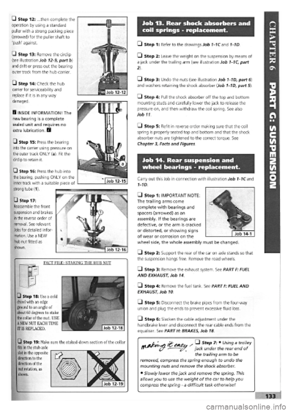
Q Step 12: ...then complete the
operation by using a standard
puller with a strong packing piece
(arrowed) for the puller shaft to
'push' against.
G Step 13: Remove the circlip
(see illustration Job
12-9,
part b)
and drift or press out the bearing
outer track from the hub carrier.
• Step 14: Check the hub
carrier for serviceability and
replace if it is in any way
damaged.
D INSIDE INFORMATION! The
new bearing is a complete
sealed unit and requires no
extra lubrication. D
• Step 15: Press the bearing
into the carrier using pressure on
the outer track ONLY (a). Fit the
circlip to retain it.
• Step 17:
Reassemble the front
suspension and brakes
in
the reverse order of
removal. See relevant
Jobs
for detailed infor-
mation. Use a NEW
hub nut fitted as
shown.
FACT FILE: STAKING THE HUB NUT
• Step 18: Use a cold
chisel
with an edge
ground to an angle of
about 60 degrees to stake
the
collar of the nut. USE
A
NEW NUT EACH TIME
IT IS REPLACED.
Q Step 19: Make sure the staked-down section of the collar
fits
in the stub axle
slot
in the opposite
direction to the
direction of the
nut
rotation, as
shown.
• Step 1: Refer to the drawings Job 1-1Cand 1-1D.
• Step 2: Leave the weight on the suspension by means of
a jack under the trailing arm (see illustration Job
1-1C,
part
• Step 3: Undo the nuts (see illustration Job
1-1D,
part
6)
and washers retaining the shock absorber (Job
1-1D,
part 5).
• Step 4: Pull the shock absorber off the top and bottom
mounting studs and carefully lower the jack to release the
pressure on, and then withdraw the coil spring. See also
Job 11
O Step 5: Refit in reverse order making sure that the coil
spring is properly seated top and bottom and that the shock
absorber nuts are tightened to the correct torque. See
Chapter
3,
Facts and Figures.
Job 14. Rear suspension and
wheel bearings - replacement.
Carry out this Job in connection with illustration Job
1-1C
and
1-1D.
• Step 1: IMPORTANT NOTE:
The trailing arms come
complete with bearings and
spacers (arrowed) as an
assembly. If the bearings are
defective, or the arm is cracked
or distorted, or showing signs
of wear or corrosion on the
wheel side, the whole assembly must be changed.
Q Step 2: Support the rear of the car on axle stands so that
the suspension hangs free. Remove the road wheels.
• Step 3: Remove the exhaust system. See PART F: FUEL
AND EXHAUST, Job 14.
• Step 4: Remove the fuel tank. See PART F: FUEL AND
EXHAUST, Job 10
• Step 5: Disconnect the brake pipes from the four-way
union and plug the ends to prevent excessive fluid loss.
Q Step 6: Slacken the cable adjustment under the
handbrake lever and disconnect the rear cable ends from the
equaliser. See PART H: BRAKES, Job 18
/ • Step 7: • Using a trolley
jack under the rear end of
the trailing arm to be
removed, compress the spring enough to undo the
mounting nuts and remove the shock absorber.
• Slowly lower the jack and remove the spring. This
allows you to use the weight of the car to help you
compress the spring
-
a difficult task otherwise!
Q Step 16: Press the hub into
the bearing, pushing ONLY on the
inner track with a suitable piece of
strong tube (1).
Page 130 of 171

• Step 8:
Support the
axle beam with
the jack and
undo the
mounting bolts
(arrowed and
indicated by
operator with
socket bar).
Lower the
complete unit
from the car.
IMPORTANT NOTE: In this shot, the top shock absorber
mountings have been disconnected, leaving the shock
absorber fitted to the suspension and the coil springs in
place. We recommend 'our' approach, covered in Step 7!
• Step 9: Undo the bolts securing the anti-roll bar and
remove it. (See Job 9.) Disconnect the brake pipes from the
side to be worked on and remove the brake drum.
Q Step 10: Remove the hub cap (see illustration Job 1-1D,
part 13) by carefully tapping and levering with a screwdriver.
• Step 11: Undo the hub nut (see illustration Job 1-1D,
part
10).
PART H: BRAKES
• Step 12: A special tool
(1857508000) or a VERY
strong Allen key (a) will be
required to reach into the
hub (b), and plenty of
leverage!
Q Step 13: Remove the
hub and inspect the bearing
for roughness or noise or
roughness when turning it by hand.
E3 INSIDE INFORMATION! The bearing is lubricated for
life and is only supplied as an assembly with the hub. B
• Step 14: Inspect the stub axle pin (see illustration Job
1-
1D, part
12)
for any signs of damage or distortion. Replace if
in doubt.
Q Step 15: Refitting is the reverse of removal but note the
following:
• See Chapter
3,
Facts and Figures for all tightening
torques as you progress through the assembling.
• Use new hub nuts and fully tighten once the suspension is
mounted to give you stability.
• Refer to PART H: BRAKES when refitting the brake parts
and bleeding the brakes.
PART H: Contents %
Job 1. Understanding Tipo/Tempra brakes.
Job 2. Front brake pads
-
replacement.
Job 3. Front brake caliper
-
replacement.
Job 4. Front brake disc
-
replacement.
Job 5. Rear brake shoes
-
replacement.
Job 6. Rear wheel cylinder
-
replacement.
Job 7. Rear brake disc pads
-
replacement.
Job 8. Rear brake caliper
-
replacement.
Job 9. Rear brake disc
-
replacement.
Job 10. Master cylinder
-
replacement.
Job 11. Servo check
-
remove and refit.
Job 12. Pressure regulating valve, non-ABS system -
replacement and adjustment.
Job 13. Pressure regulating valves, ABS system
-
replacement
and adjustment.
Job 14. RPM sensors, ABS systems
-
replacement.
Job 15. Flexible hoses
-
replacement.
Job 16. Metal pipes
-
replacement.
Job 17. Brake bleeding.
Job 18. Handbrake cables
-
replacement.
Job 1. Understanding
Tipo/Tempra brakes.
• Point
1
A: This is the standard disc/drum system used on
cars without anti-lock brakes, shown here in left hand drive
form.
1 - fluid reservoir and master cylinder 2 - servo 3
-
front disc brakes
4 - handbrake lever 5 - rear drum brakes 6
-
four way pipe union 7 - load proportioning/ pressure limiting valve
Job 1-1A
1 - front disc brakes 2
-
front flywheel 3 - front wheel RPM sensors 4 - hydraulic control unit 5 - brake light switch 6 - device failure warning light switch
7 - rear flywheel 8 - main control relay with excess voltage protection 9 - electronic control unit 10 - rear disc brakes 11 - rear wheel RPM sensors 12 - load proportioning/pressure limiting valve Job
1-1B
Page 136 of 171
Job 13. Pressure regulating
valves, ABS system - replacement
and adjustment.
Job 14. RPM sensors, ABS
systems - replacement.
H INSIDE INFORMATION! The RPM sensors align with
the flywheels (which look like toothed rings) and which
rotate with the road wheels. The sensors measure the
vehicle's running speed, acceleration, deceleration and
wheel creep. These signals are sent to the electronic
control unit and allow it to instruct the hydraulic control
unit to vary the brake fluid pressure to each wheel as
necessary to prevent the brakes from locking up. E3
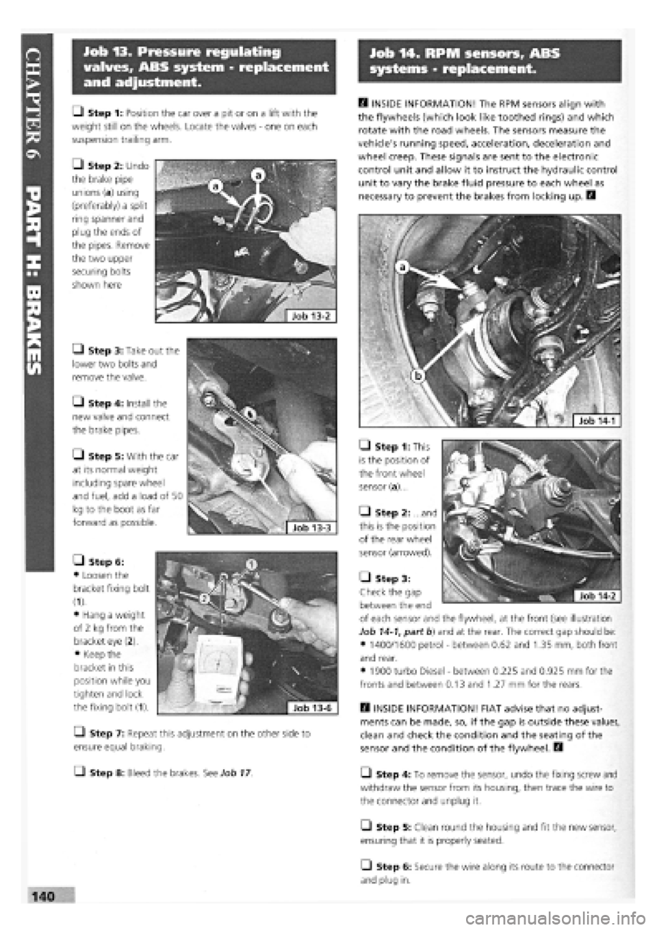
• Step 1: This
is the position of
the front wheel
sensor (a)...
• Step 2: ...and
this is the position
of the rear wheel
sensor (arrowed).
H INSIDE INFORMATION! FIAT advise that no adjust-
ments can be made, so, if the gap is outside these values,
clean and check the condition and the seating of the
sensor and the condition of the flywheel. D
L_l Step 4: To remove the sensor, undo the fixing screw and
withdraw the sensor from its housing, then trace the wire to
the connector and unplug it.
• Step 5: Clean round the housing and fit the new sensor,
ensuring that it is properly seated.
O Step 6: Secure the wire along its route to the connector
and plug in.
• Step 1: Position the car over a pit or on a lift with the
weight still on the wheels. Locate the valves
-
one on each
suspension trailing arm.
• Step 2: Undo
the brake pipe
unions (a) using
(preferably) a split
ring spanner and
plug the ends of
the pipes. Remove
the two upper
securing bolts
shown here
• Step 3: Take out the
lower two bolts and
remove the valve.
• Step 4: Install the
new valve and connect
the brake pipes.
• Step 5: With the car
at its normal weight
including spare wheel
and fuel, add a load of 50
kg to the boot as far
forward as possible.
• Step 6:
• Loosen the
bracket fixing bolt
(1).
• Hang a weight
of 2 kg from the
bracket eye (2).
• Keep the
bracket in this
position while you
tighten and lock
the fixing bolt (1).
Q Step 7: Repeat this adjustment on the other side to
ensure equal braking.
• Step 8: Bleed the brakes. See Job
17
• Step 3:
Check the gap
between the end
of each sensor and the flywheel, at the front (see illustration
Job
14-1,
part b) and at the rear. The correct gap should be:
• 1400/1600 petrol
-
between 0.62 and 1.35 mm, both front
and rear.
• 1900 turbo Diesel
-
between 0.225 and 0.925 mm for the
fronts and between 0.13 and 1.27 mm for the rears.
Page 137 of 171
Job 15. Flexible hoses -
replacement.
• Step 8: Bleed the brakes, see Job
17
H INSIDE INFORMATION: When disconnecting brake
pipes or hoses, it is helpful to minimise brake fluid loss.
This can be done by unscrewing the master cylinder
reservoir cap, laying a sheet of plastic across the
opening, and refitting the cap. This will prevent atmos-
pheric pressure from pushing the fluid out of opened
lines. D
/ • If a rigid pipe starts to
twist with the union, grip
the pipe as lightly as
possible, and see if you can stop it from turning.
• If not, cut through the pipe with a junior hacksaw
and replace the length of rigid pipe.
Job 16. Metal pipes -
replacement.
B INSIDE INFORMATION: When disconnecting brake
pipes or hoses, it is helpful to minimise brake fluid loss.
This can be done by unscrewing the master cylinder
reservoir cap, laying a sheet of plastic across the
opening, and refitting the cap. This will prevent atmos-
pheric pressure from pushing the fluid out of opened
lines. A pipe spanner makes the job much easier! B
Step 1: Undo the unions at each end of a pipe length.
Patience is often required because of the union seizing both in
its threads and on the pipe. See MAKING IT EASY! after Job
15,
Step 8 Use penetrating oil to help free seized unions, and
use a split-ring spanner rather than an open-ended one, to
reduce the risk of rounding off the union nuts.
• Step 2: Detach the pipe length from its securing clips and
remove it.
i^vj ens s * ^ step 3: where possible, use the old pipe as
a pattern to shape the new
one prior to fitting.
• Step 4: Follow the original route and secure the pipe in
the body clips.
Q Step 5: Connect the unions and bleed the system. See
Job
17
Job 17. Brake bleeding.
B INSIDE INFORMATION: Unless the master cylinder or
pressure regulating valve has been disturbed, it will only
be necessary to bleed the end of the braking system
which has been opened. If bleeding the whole system,
start bleeding at the left-hand rear brake. B
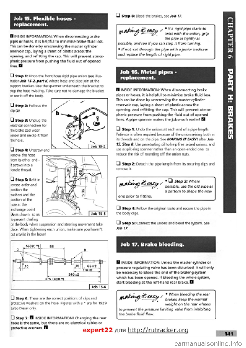
G Step 6: These are the correct positions of clips and
protective washers on the hose. Figures with a * are for 1929
turbo Diesel only.
• Step 7: B INSIDE INFORMATION! Changing the rear
hoses is the same, but there are no electrical cables or
protective washers. B
s • When bleeding the rear
brakes, keep the normal
weight on the rear wheels
to prevent the pressure limiting valve from inhibiting
the brake fluid flow.
expert22 f
\9\ http://rutracker.org 141
Ul Step 1: Undo the front hose rigid pipe union (see illus-
tration Job
15-2,
part a) where hose and pipe join at the
support bracket. Use the spanner underneath the bracket to
stop the hose twisting. Take care not to damage the bracket
or tear it off the body.
• Step 2: Pull out the
dip (b).
G Step 3: Unplug the
electrical connection for
the brake pad wear
sensor and unclip it from
the hose.
G Step 4: Unscrew and
remove the hose
from its other end -
it screws into a
female thread.
• Step 5: Refit in
reverse order and
position the
washers and the
position of the
hose at the
anchorage point
(A) as shown, so as
to prevent chafing
on the body when suspension and steering movement take
place. When tightening each union, make sure you haven't
put a twist in the hose!
Page 171 of 171

A Accelerator linkages and cables 118,119 Aerial 112 Airbag 14, 63, 128 Air cleaner/filter 51 Air Conditioning 12,41 Alternator, drive belt . . 49, 50, 110 Antifreeze 43, 44 Anti-roll bars 131 Auto-Biography 1 Automatic transmission fluid 45 gear selector cable 102
B Ball-joints steering and suspension 57 Battery disconnecting 36 electrolyte 36 safety 7 Bellows, steering gear (see 'Gaiters') Bonnet 15, 143 Brakes 59 to 62, 134 to 142 bleeding 141 caliper 59 to 61, 135, 137 cylinder (master) 138 discs, front 59, 135 discs, rear 61, 137 drums 60, 136 fluid, check level 35,36 handbrake 61, 142 hoses/pipes 62, 141 pads 59, 135, 137 pressure regulating/proportioning . . . valve (ABS) 140 pressure regulating/proportioning valve (Non-ABS) 139 RPM sensors (ABS systems) .... 140 safety 7 servo 138 shoes 135 wear sensors (non-ABS) 60 Bulb renewal (see 'Lights') Bushes 57 Bumper removal and refitting. 146
c Cables accelerator 118,119 automatic transmission ... 101, 102 choke 119 clutch 46, 101 handbrake 61 Caliper, brakes (see 'Brakes') Camshaft belt 43, 66 Capacities 19,154 Carburettor adjustment 53 removal 117 Catalytic converter 54, 55 safety 6 Central locking 114 Choke 119 Clutch adjustment 46, 100 hydraulic 46, 105 replacement 100 cable 46, 101 Coil, ignition 47, 107, 108 Coil spring 57 Constant Velocity (C.V.) joints (see 'Driveshaft') Contents 4 Controls and switches ... 10 to 14 Cooling system .. 35, 43, 106 to107 change coolant 43 radiator pressure cap 35 Crankcase ventilation system 42 Cylinder head Diesel 87 to 93
Petrol 67 to 73
D Data 17 to 27 Diesel bleeding the system 126,127 fuel filter 52 glow plugs 115 injection pump 56,124 injectors 126 Disc, brakes (see 'Brakes') Distributor 108, 109 cap 47 Marelli Breakerless 48 Marelli Digiplex 2 48, 49 Doors hinges 62 locKs and handles 147 to 150 removal and refitting 147 trim panels 146 Drivebelts alternator 49, 50, 110 camshaft 43 Driveshaft C.V. joints 103 gaiters 45, 103 removal and refitting 103 Drum (see 'Brakes')
E Electrical system 110 to 115 Electronic control module 54 safety 7 Emergency starting 16 Emissions 31, 51 to 56 control 53, 54 legal limits 31 Engine bay layouts 34 Engine dismantling Diesel 95 Petrol 73 Engine mountings Diesel 95 Petrol 83 Engine oil (see 'Oil') check level 34 Engine refitting Diesel 94 Petrol 82 Exhaust manifold 56 Exhaust 56 system 56, 122 Expansion tank 35
F Facts & Figures 17 to 27 Fan 50, 106 Fast idle carburettor 53, 54 fuel injection 54 diesel 55 Filter air 51 diesel 52 petrol 52 oil (see 'Oil filter') pollen 63 Fire Extinguisher . 6 Fluoroelastomers, safety 8 Fuel cut-off switch 13 Fuel gauge 114 Fuel injection 52, 54, 55, 117 Fuel lines/pipes 51 Fuel pump electric 120 mechanical 120 Fuel system 51 to 56 evaporation control system . 54,122 Fuel tank 121 Fumes, safety 6 Fuses 40
Gearbox (transmission) .... 44 to 46 oil (automatic) . . 45 oil (manual) 44 Generator drive belt (see 'Alternator, drive belt')
H Handbrake 61, 142 Headlights (see 'Lights') adjustment 62 bulb replacement 37 Headrest 153 Heater 11 Hoses/pipes (see 'Pipes and hoses') HT leads 47 Hub front 104 rear 134
I Identification numbers 27 Idle speed adjustment (see 'Carburettor') Ignition system 46 to 51, 107 to 109 coil 47,48 safety 7 Ignition timing 19, 48 to 50 Instruments 110 panel lights 10 Intercooler 123, 124
J Jacking safety 5 wheelchange 15, 16 Jump leads (Jump starting) 16
L Lambda sensor ... 54, 55, 121, 122 Lights fog lights 13, 38 hazard warning 13 headlights 13,37 indicators 13, 37 interior 15, 39, 40 MoT 28 number plate 39 rear lights 38 reversing lights 39 sidelights 13, 37 Locks and latches 9, 10, 62 Lubricants 154
m Manifold fixings 56 Mirrors 14, 150 Mixture adjustment (see 'Carburettor') Model years 17, 18 MoT, getting through 28 to 31
m Number plates (lights) . . 28, 39, 145
o Oil change disposal 7, 8 engine 41, 42 transmission 44, 45 safety 7 Oil filler cap 35 Oil filter 41 Oil level engine 34, 35 gearbox 44, 45 topping up 35
P-Pads, brake (see 'Brakes') Pipes and hoses brakes 62, 138, 141 hot air 121 radiator (cooling system) 43 Plastics, safety 7 Production changes 17, 18
ft Radiator .* 106 Raising the car 5 Repair data 20 Road test, brakes and steering ... 63 Rotor arm 47, 49
s Safety First! 5 to 8 Seats 14, 151 to 153 mountings 62 Seat belts mountings 62 pretensioners 151, 152 Servicing Your Car 32 to 63 Shock absorbers 57,131 Shoes, brake (see 'Brakes') Sidelights (see 'Lights') Spark plugs 47, 154 Specifications (see 'Facts & Figures') Speedometer cable 110 Starter motor 110 Steering 57, 58, 127 to 131 lower wishbone 127, 130 power steering 58, 130 rack gaiters 58, 133 Steering wheel 128 Sun roof 151 Suspension ... 57 to 59, 127 to 134 front 57, 127, 131 rear 58, 59, 128, 133 strut 57, 131
T Tailgate wiper (see 'Windscreen wipers') Tailgate and strut 144 Thermostat 107 Throttle cable and pedal (see 'Accelerator, linkage and cables') Timing belt 43 Diesel 85 to 87 Petrol 65, 66 Torque wrench settings ... 23 to 27 Track control arm (inner bushes). . 57 Track rod ends 57, 58, 128 Transmission. . 80 to 83, 95, 98 to 106 removal 80 to 82 separation and reconnection (Diesel). . 95 separation and reconnection (Petrol). . 83 Transmission fluid 44, 45 Turbocharger replacement 122 to 124 Tyre checking 30, 36 pressures 18,36
u Universal joints 28, 58 Using your car 9 to 16
¥ Vacuum unit, distributor 48 Valve clearances 42, 43, 79, 93 Valve grinding 72 Vehicle Identification Numbers (VIN) 27
w Washer fluid reservoir 36 Water pump 107 Wheel alignment 28 Wheel bearings 57, 58 Wheel bolts 59 Wheel changing 15,16 Wheel cylinder 137 Wheel sizes 18 Windscreen, damage 29,162 Window regulator 147 to 149 Windscreen washers 112 Windscreen wipers 13,111 Wiring diagrams 155 to 174
Gaiters 30, 57
expert22 fl/ia http://rutracker.org