1988 FIAT TEMPRA drain bolt
[x] Cancel search: drain boltPage 29 of 171

Thanks
are due to the excellent, knowledgeable and helpful staff at FIAT main dealers, Ryauto of Amblecote, in the West
Midlands for supplying vehicles and for their assistance with this chapter. In particular, thanks are due to the efficient Maurice
Hough, Service Manager, the experienced Foreman, Tony Morris, and young demon mechanic, Matthew Worsfold.
Some of the suggested inspection/replacement intervals may not correspond to those shown in the original handbook. The suggested
schedule, based on FIAT'S recommendations, takes into account the age of the vehicle and the annual MoT test in the UK.
In practice, because of the split between (mainly) 12 month/9,000 mile and 18 month/13,500 mile intervals, you will need to
service your Tipo or Tempra at most, if not every, 6 month interval.
IMPORTANT NOTE: Each service should be carried out at EITHER the recommended mileage OR the recommended time
interval, whichever comes first.
SERVICE INTERVAL CHART
SERVICE INTERVALS: KEY
A
-
Every week, or before every long journey. F
-
Every 3 years or 27,000 miles.
B
-
Every 6 months, or 4,500 miles. G
-
Every 4 years or 36,000 miles.
C - Every 12 months, or 9,000 miles. H
-
Every 6 years or 54,000 miles.
I
-
Every 63,000 miles. D - Every 18 months , or 13,500 miles.
H
-
Every 6 years or 54,000 miles.
I
-
Every 63,000 miles.
E
-
Every 2 years or 18,000 miles J
-
Every 72,000 miles.
PART A: REGULAR CHECKS
SERVICE INTERVALS
Job 1. Engine oil
-
check level A
Job 2. Cooling system
-
check level A
Job 3. Brake/clutch fluid
-
check level A
Job 4. Battery
-
check electrolyte level A
Job 5. Screen washer fluid
-
check level A
Job 6. Tyres
-
check pressures and
condition (road wheels) A
Job 7. Check lights/change bulbs A
PART B: THE ENGINE AND
COOLING SYSTEM
Job 8
-
Petrol. Change engine oil and filter C
Job 8
-
Diesel. Change engine oil and filter B
Job 9. Check crankcase ventilation H
Job 10. Check/adjust valve clearances D
Job 11. Check camshaft timing belt F
Job 12. Change camshaft timing belt I
Job 13. Check cooling system C
Job 14. Change engine coolant E
PART C: TRANSMISSION
Job 15. Check manual gearbox oil level C
Job 16. Change manual gearbox oil J
Job 17. Check auto, transmission fluid level C
Job 18. Change auto, transmission
fluid and filter F
Job 19. Check driveshaft gaiters C
Job 20. Check/adjust clutch C
Job 21. Check auto, transmission selector
cable E
PART D: IGNITION AND ELECTRICS
SERVICE INTERVALS
Job 22. Check/clean/gap spark plugs B
Job 23. Change spark plugs D
Job 24. Check/clean HT leads and
distributor cap C
Job 25. Check ignition timing C
Job 26. Check/adjust drive belt/s D
Job 27. Check electric fan operation C
Job 28. Run diagnostic ignition/injection test D
PART E: FUEL AND EXHAUST
Job 29. Check fuel pipes for leaks C
Job 30. Change petrol air filter D
Job 31. Change diesel air filter C
Job 32. Change petrol fuel filter F
Job 33. Drain diesel fuel filter B
Job 34. Change diesel fuel filter C
Job 35. Check/adjust petrol engine idle
and emissions C
Job 36. Check emission/evaporative/EGR systems F
Job 37. Check Lambda sensor F
Job 38. Check/adjust diesel idle speed C
Job 39. Check/adjust diesel injection timing E
Job 40. Check inlet and exhaust manifold fixings D
Job 41. Check exhaust system C
PART F: STEERING AND
SUSPENSION
Job 42. Check front wheel bearings C
Job 43. Check front suspension C
Job 44. Check steering column, joints and rack C
Job 45. Check power steering fluid C
Job 46. Check rear wheel bearings C
Job 47. Check rear suspension C
Job 48. Check wheel bolts for tightness C
Page 38 of 171

8D. To prevent the rubber sealing
ring on the new filter from
buckling or twisting out of shape
while tightening, smear it with
clean oil.
8E. Screw the new filter onto the
stub by hand. When the rubber
sealing ring contacts its seat,
continue to turn the
filter a further 3/4
of a turn, by hand
only. Over-tight-
ening the filter
makes it difficult to
remove at the next
oil change and can
buckle the seal,
causing a leak.
E3 INSIDE INFORMATION: It isn't necessary to use
excessive force when refitting the sump plug. Simply grip
the spanner (no need for an extension, now!) so that the
thumb rests on the spanner head, limiting the amount of
leverage that can be applied. Use firm pressure only.
Before refitting the plug, wipe around the drain hole
with a piece of clean cloth to remove any dirt. II
8F. Pour in the correct quantity of
Selenia engine oil (see Chapter
3, Facts and Figures) and check
the level against the dipstick.
Note that the empty oil filter will
cause the level to drop slightly
when the engine is started and
the oil flows into it. Before using
the car, run the engine for two
minutes, turn off, leave to stand
for a few minutes and then
recheck and correct the oil level.
• Job 9. Check crankcase ventilation.
10B. H INSIDE
INFORMATION: If
the gasket sticks
-
which it
frequently does -
DON'T lever the
Q Job 10. Check/adjust valve clearances.
The valve gear clearances need to be checked at the appro-
priate intervals, when the engine is cold.
ALL PETROL AND DIESEL ENGINES
10A. Remove the
air cleaner (where
necessary)
-
see Job
30 then remove the
bolts holding the
camshaft cover in
place. This is the
petrol engine with
air filter removed...
cover or your
could or you could
easily damage it.
Use a spatula to push through the soft joint until the
gasket/cover comes free. D
10C. E3 INSIDE
INFORMATION:
The oil level inside
the housing is
above the level of
the bottom of the
cover plate on
these engines.
Try: i) raising the
front of the car as
high as safely possible, so that oil drains out of the back
of the housing; ii) stuffing cloths beneath the opening
and have more ready, for mopping up; iii) being ready to
clean off the front of the engine with degreaser, when
the job is finished. D
10D. The valve
clearance is
measured directly
beneath the cam
and must be
checked when the
high point of the
cam (arrowed) is
pointing directly
upwards and away
9. Check the
condition of the
breather hose from
the valve cover or
cam cover to the air
cleaner. If the pipe
has become
blocked or
damaged, replace
it, transferring the
flame trap from inside the old pipe to the new one. On some
models, you will have to remove the air filter housing to get at
the crankcase ventilation pipe beneath. Note this type of
spring clip
-
use pliers to slacken-off when removing or re-
fitting.
Try different feeler gauge thicknesses until you find one that's
a tight sliding fit between cam and follower. Make a written
note of each clearance starting with number
1
at the timing
belt end of the engine.
from the cam follower.
Page 41 of 171
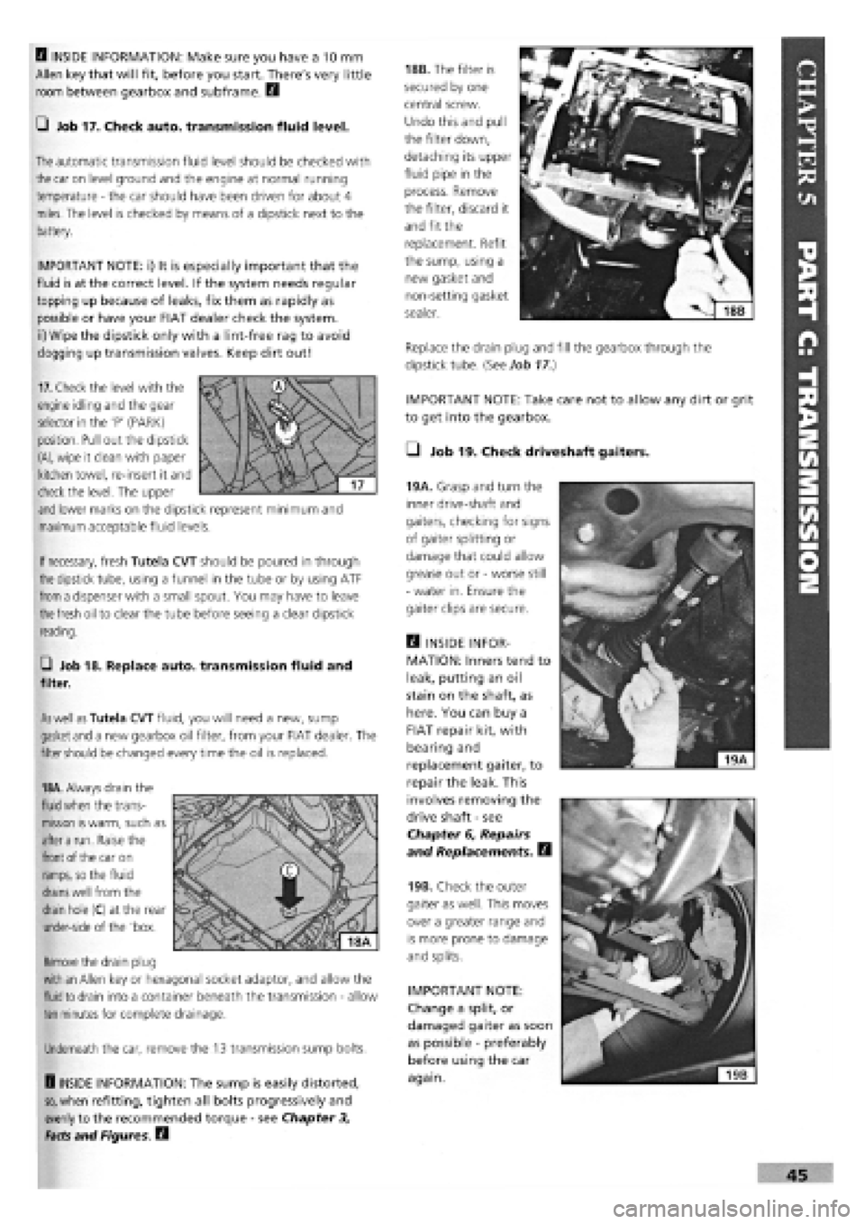
IMPORTANT NOTE: Take care not to allow any dirt or grit
to get into the gearbox.
• Job 19. Check driveshaft gaiters.
45
B INSIDE INFORMATION: Make sure you have a 10 mm
Allen key that will fit, before you start. There's very little
room between gearbox and subframe. B
Q Job 17. Check auto, transmission fluid level.
The
automatic transmission fluid level should be checked with
the
car on level ground and the engine at normal running
temperature
-
the car should have been driven for about 4
miles. The level is checked by means of a dipstick next to the
battery.
IMPORTANT NOTE: i) It is especially important that the
fluid is at the correct level. If the system needs regular
topping up because of leaks, fix them as rapidly as
possible or have your FIAT dealer check the system,
ii) Wipe the dipstick only with a lint-free rag to avoid
clogging up transmission valves. Keep dirt out!
18B. The filter is
secured by one
central screw.
Undo this and pull
the filter down,
detaching its upper
fluid pipe in the
process. Remove
the filter, discard it
and fit the
replacement. Refit
the sump, using a
new gasket and
non-setting gasket
sealer.
Replace the drain plug and fill the gearbox through the
dipstick tube. {See Job
17.)
19A. Grasp and turn the
inner drive-shaft and
gaiters, checking for signs
of gaiter splitting or
damage that could allow
grease out or
-
worse still
-
water in. Ensure the
gaiter clips are secure.
Q INSIDE INFOR-
MATION: Inners tend to
leak, putting an oil
stain on the shaft, as
here. You can buy a
FIAT repair kit, with
bearing and
replacement gaiter, to
repair the leak. This
involves removing the
drive shaft
-
see
Chapter 6, Repairs
and Replacements. B
19B. Check the outer
gaiter as well. This moves
over a greater range and
is more prone to damage
and splits.
IMPORTANT NOTE:
Change a split, or
damaged gaiter as soon
as possible
-
preferably
before using the car
again.
If
necessary,
fresh Tutela CVT should be poured in through
the
dipstick tube, using a funnel in the tube or by using ATF
from
a dispenser with a small spout. You may have to leave
the fresh
oil to clear the tube before seeing a clear dipstick
reading.
G Job 18. Replace auto, transmission fluid and
filter.
As well as
Tutela CVT fluid, you will need a new, sump
gasket
and
a new gearbox oil filter, from your FIAT dealer. The
filter
should
be changed every time the oil is replaced.
18A.
Always drain the
fluid when
the trans-
mission
is
warm, such as
after a
run. Raise the
front
of the car on
ramps,
so the fluid
drains well
from the
drain
hole (C) at the rear
under-side of the 'box.
Remove
the drain plug
with an
Allen key or hexagonal socket adaptor, and allow the
fluid to
drain into a container beneath the transmission
-
allow
ten
minutes for complete drainage.
Underneath the car, remove the 13 transmission sump bolts.
H INSIDE INFORMATION: The sump is easily distorted,
so,
when refitting, tighten all bolts progressively and
evenly to the recommended torque
-
see Chapter 3,
Facts and Figures. B
17.
Check the level with the
engine idling and the gear
selector in the 'P' (PARK)
position. Pull out the dipstick
(A),
wipe it clean with paper
kitchen towel, re-insert it and
check the level. The upper
and
lower marks on the dipstick represent minimum and
maximum acceptable fluid levels.
Page 63 of 171

Job 2. Petrol engine. Cylinder
head • removal.
• Step 1: Take note of the parts shown in this drawing -
which is also relevant to several other jobs on Tipo and
Tempra petrol engines.
7
-
cirdip 8
-
plate 9
-
flywheel 10-spigot bearing
11 -
thrust bearing 12
-
main bearing 13-crankshaft
14 - sump 15 - sump gasket 16 - oil seal 17 - auxiliary shaft cover 18 - gasket 19 - front oil seal housing 20 - oil seal 21 - bush 22 - auxiliary shaft 23 - drive gear 24 - dipstick 25 - oil pump 26 - auxiliary shaft sprocket
1
-
piston 2
-
gudgeon pin 3
-
connecting rod 4
-
big-end bearing 5
-
big-end bolt 6
-
small-end bush
27 28 29 30 31 32 33 34 35 36 37 38 39
turbo 40 - exhaust manifold - turbo 41 - exhaust manifold - non-turbo 42 - heated air duct 43 - camshaft cover 44 - camshaft housing 45 - oil seal 46 - camshaft 47 - tappet shim 48 - oil seal 49 - tappet body 50
-
valve, top cap Job 2-1
- crankshaft sprocket - tensioner pulley - timing belt cover - camshaft sprocket - camshaft belt - bracket - end plate - cylinder head gasket - cylinder head - timing belt - rear cover - inlet manifolds - turbo - plenum chamber
-
turbo - inlet manifold - non-
51 - valve spring - inner 52 - valve spring
-
outer 53 - valve, top cap 54 - washer 55 - valve guide 56 - valve 57 - end plate 58 - rear oil seal housing 59 - block 60 - oil seal 61 - sump drain plug
Q INSIDE INFORMATION! • Before removing the
cylinder head, make sure the engine is stone cold.
• Undo the cylinder head bolts strictly in the order laid
out in Step 18.
• These precautions help to prevent cylinder head
distortion.
• The new cylinder head gasket should stay in its
packaging until required, to avoid contamination by oil
or grease.
B
FACT FILE: SPECIAL TOOL PROBLEMS
SOLVED!
• It is possible to remove and replace the
cylinder head complete with the camshaft
housing - but it is very difficult without
FIAT's special cranked tool to get round the camshaft
housing.
• You CAN undo the bolts with a ring spanner, but you
CAN'T torque them down properly again!
• Because the gasket between the housing and the head could
also be suspect, we strongly recommend that you do it 'our'
way, by removing the camshaft housing even though you will
have to re-set the valve clearances.
Page 64 of 171

SAFETY FIRST! • Step 7:
Disconnect the
electrical leads from
the following: the
inlet manifold
• Step 2: Disconnect both battery leads, negative
terminal first.
Q Step 3: Drain the cooling system and depressurise the
fuel system, if yours is a fuel injection engine
-
see PART
F:
FUEL AND EXHAUST
• Step 6B:
INJECTION
ENGINES.
Disconnect the
engine end of the
accelerator cable (a),
the idle speed check
actuator (b) and the
injector supply (c).
• Step 8: Detach
the exhaust
downpipe from the
manifold.
• Step 9: Remove
the dipstick
(arrowed) and the
cylinder head
coolant temperature
sensor (arrowed).
• Step 10: Also remove all the HT leads (along with the
distributor cap). Place them to one side.
• Step 11: Undo the brake servo hose from the manifold.
Q Step 4: Remove the air cleaner by releasing the spring
clips (a) at the front of the unit and the screw on the top face
(b) and disconnect the hoses
recovery pipe clips from beneath the rear of the housing, once
it is free to lift up.
Q Step 5: Disconnect the crankcase vent hose from the
cylinder head and the inlet tract or the SPI injector unit, as
appropriate and blank off with a bolt of suitable size.
• Step 6A:
CARBURETTOR
ENGINES.
Disconnect the
engine end of the
accelerator cable
from its idler and
the choke cable
from its mounting.
Q Step 12: Remove the
water hoses connected to
the inlet manifold and
thermostat.
• Step 13 A:
CARBURETTOR
ENGINES. Disconnect the
fuel pipe from the carbu-
rettor and both pipes
from the fuel pump.
(Label both the pipes and
stubs so that they will be
reconnected the
right way round.)
• Step 13B:
INJECTION
ENGINES.
Disconnect the fuel
supply and return
hoses from the
injector unit housing
(a). Plug the ends.
• Step 14A: CARBURETTOR ENGINES. Disconnect the
distributor vacuum pipe and oil vapour pipes from the carbu-
rettor.
vacuum sensor
(arrowed), the
manifold coolant
temperature sensors
(arrowed) and the
throttle position
switch and any
other leads which your engine may have.
Page 66 of 171

• Step 26:
Check that
nothing remains
attached to, or
obstructs the
cylinder head and
lift it clear of the
block. If stuck, it
is permissible to
tap the head
lightly with a soft mallet to free it. Never use a wedge
between the joint faces and remember that the head will not
slide off as it is located on dowels.
Job 3. Petrol engine.
Cylinder head and camshaft
housing - refitting.
• Carburettor cleaner
-
or
the purpose-made Loctite
'Chisel' aerosol spray,
available from your FIAT dealer, will help to remove
pieces of
stuck-on
gasket.
o
(
V.
o
o
o
o o o
o o e
• • • • •
0 0 O 0 o
Job
3-4
grease, place it on the block with (on FIAT gaskets) this
copper-ringed hole above the correct water passage. The
gasket only fits correctly one way round.
• Step 3:
Lower the
cylinder head into
position and
locate it on the
two dowels (see
illustration Job
3-2, arrowed).
Refer to the illustration to Job
2-1
in connection with the
work described here.
• Step 4: The
10 main cylinder
head securing
bolts and washers
can now be
screwed in by
hand. Don't fit
the smaller ones
(arrowed) yet.
Q INSIDE INFORMATION: FIAT recommend that you
should not re-use cylinder head bolts which have been
refitted more than three times before. Fit new ones if in
doubt, so that you can ensure reliability. B
• Step 1: Lubricate the cylinder head bolts and washers
and leave them to drain for AT LEAST 20 minutes before
fitting them.
• Step 5B:
Tighten the head
down to the first
torque setting,
following the
correct tightening
order.
Q Step 27: Remove the old gasket.
IMPORTANT NOTES: • Here, we show how to refit the
head and camshaft housing, separated. The head
complete with housing cannot be torqued down
correctly without the use of FIAT's special, cranked
spanner for use on the semi-hidden head bolts.
• The valve clearances will have to be re-set. See Job 7.
Clean the block and cylinder head mating surfaces with a
straight edge, taking particular care with the light alloy head.
Any gouging of the metal could prove very expensive to have
put right!
Make sure that all the holes and coolant passages are clear of
any foreign matter, particularly the cylinder head bolt holes
which must be clear right down to the bottom.
• Step 5C: In
the same order,
tighten the bolts
to their second
torque setting.
• Step 2: With
the block face
perfectly clean,
remove the
cylinder head
gasket from its
wrapping and,
keeping it away
from oil or
Tighten by another (second) 90 degrees, bolt-by-bolt, again in
the correct order.
• Step 5D:
Tighten each bolt,
once again in the
correct order, by
a further 90
degrees. You
could use an
angle gauge
(available from
auto-accessory
stores) in order to
be precise.
Q Step 5A: Tighten the 10 larger bolts in their correct
sequence as shown in illustration Job
3-4.
All of the settings
are shown in
Chapter
3,
Facts
and Figures.
Page 76 of 171

Job 8. Petrol engine/transmission
- removal.
IMPORTANT NOTE: See PARTB: TRANSMISSION for
gearbox removal by itself.
H INSIDE INFORMATION! The complete engine/trans-
mission unit is removed and replaced from under the car
- and this applies to all types. Make sure you can raise
the front of the car high enough (and support it safely
and securely!) to allow the power unit to be pulled clear
from underneath, before starting work! 13
• Step 1: Remove the bonnet
-
see PARTI: BODY AND
INTERIOR, Job 1.
• Step 5:
Disconnect the
carburettor or
injector fuel lines,
choke and throttle
cables and hoses and
electrical connections
(arrowed).
Q Step 6: Disconnect the starter motor cables, HT leads,
fuel pump lines, sensors and electrical connectors arrowed.
Job
8-7
• Step 2: Disconnect the battery earth lead.
• Step 3: Drain the cooling system and the engine oil.
Disconnect all hoses shown.
• Step 7: Disconnect the clutch cable (3) or clutch slave
cylinder, if hydraulic, the earth cable (2) and the reversing
lights switch cable
(1)
from the top of the gearbox.
• Step 8: Disconnect the alternator cables.
Q Step 9: Slacken the front wheel bolts, raise the car and
support securely on axle stands. Remove the wheels.
• Step 10: Drain
the gearbox oil.
• Step 4:
Remove the air
filter-to-engine
connections
-
earlier type illus-
trated. (There are
some hose
connections
underneath on
the later type,
mounted on top
of the engine.) Disconnect the electrical connection and all
other hoses from the filter housing.
• Step 11:
Remove the buttons
(gearbox side,
arrowed) fixing the
dust shield to the
wheel arch on each
side.
Page 83 of 171

Q Step B11: Undo the belt tensioner nut (see illustration
Job 13-B10, part d), then remove the timing belt.
Q Step B12: Undo the nuts securing the brake vacuum
pump to the cylinder head (see illustration Job
16-1),
and
remove it.
• Step B13: Fit FIAT tool no. 1860932000 (for setting
camshaft timing) to the vacuum pump end of the camshaft,
matching the camshaft groove (1) with the lug (2) on the tool
Secure
the tool to the cylinder head, positioning the centring
dowel
(3) as shown. The dowel must be perfectly centred on
the tool,
and if it isn't, you should adjust the hexagonal bolt
(4) with
a spanner, and centre it with tiny movements.
• Step B14:
Remove
the bolt
(arrowed) which
secures
the front
cover
to the engine
block,
then fit the
timing belt on the
crankshaft sprocket.
• Step B16:
Lock the injection
pump sprocket (see
StepA13). Now,
using FIAT tool no.
1860831000,
slacken the bolt
securing the
camshaft sprocket.
• Step B17: Continue fitting the timing belt in the
following sequence: crankshaft sprocket, fixed tensioner,
injection pump sprocket, timing sprocket, belt tensioner... and
check that the mark on the injection pump lines up with the
fixed mark on the rear cover.
• Step B18: Use the timing belt tensioner to correctly
tension the belt.
B INSIDE INFORMATION: If you do not have the correct
tensioning tool, follow Steps A16 and A17. B
• Step B19: Tighten the camshaft sprocket bolt to the 1
specified torque (see Chapter
3,
Facts and Figures).
Q Step B20: Turn the crankshaft by two revolutions
(clockwise), tighten the belt tensioner to the specified torque
(see Chapter
3,
Facts and Figures) and remove the
tensioning tools. If the belt is correctly tensioned you should
just be able to twist it through a quarter-turn when gripping it
between thumb and finger in the centre of its longest run
between sprockets. Adjust as necessary.
O Step B21: Refit the remaining components in the reverse
order of removal, then check the injection timing. See
Chapter
5,
Servicing Your Car, Job 25.
Job 14. Diesel engine.
Cylinder head - removal.
• Disconnecting the high pressure pipes on a diesel
injection system can be dangerous!
• Read the Safety First! information at the start of
PART F: FUEL AND EXHAUST SYSTEMS before
starting work.
Q Step 1: Refer to Job
13
and remove the timing belt.
• Step 2: Drain the cooling system and disconnect the air
pipes from the inlet manifold.
Q Step 3: Disconnect
and remove the oil vapour
pipes from the cylinder
block device.
Job 13-B13
• Step B15: Fit
FIAT tool
No.
1860933000 for
precise
determination
of TDC
on cylinder
No. 1. The
tool must
be secured
firmly by
two bolts
to the
crankshaft sprocket,
and by
another bolt
to the
crankshaft front cover (where the bolt was previously
removed in Step B14).