1988 FIAT TEMPRA suspension
[x] Cancel search: suspensionPage 89 of 171

Job 17. Diesel engine.
Valve clearances - adjustment.
D INSIDE INFORMATION! After carrying out Job 16,
valve clearance measurement and adjustment is now
needed. Both measurement and shim replacement are
carried out in the same manner as for the petrol engine
(.Job
7), so refer to this and also to Chapter 3, Facts
and Figures for specifications. B
Job 18. Diesel engine - removal.
moving parts with engine oil during assembly. See Chapter 3,
Facts
and Figures for specified tightening torques.
luei suppiy diiu leium pipe;>
at the injection pump...
• Step 9: ...and the stop
control supply cable. Also
disconnect the cable from
the injection pump hydraulic
advance control sensor and
the alternator cables.
• Step 10:
Disconnect the oil
feed and return
pipes between the
thermostatic valve
and the radiator
and tie clear.
I
This should
be read in connection with Job 8
Q INSIDE INFORMATION! • The turbo and non-turbo
diesel engines are essentially similar.
• The under-bonnet scene is in some ways different
because of the extra plumbing required when a turbo is
fitted.
• Locations and shapes of various items may differ, or
not exist at all on the non-turbo unit.
• As most complexity is found with the turbo engine,
I
the
following illustrations are mainly of this version.
• The power units are removed from under the car,
therefore make sure you can raise the car enough to
achieve this. Support the car firmly and safely on axle
stands. D
Q Step 1: Disconnect the negative lead from the battery
and drain
the cooling system. Q Step 2: Remove the bonnet lid.
• Step 3: Drain the transmission oil.
Q Step 4: Disconnect and remove all pipes and hoses.
Q Step 5: Undo all electrical connection and label them
with masking
tape. Write matching numbers on each male
and female
connection to assist reconnection, later.
Q Step 6: Disconnect the power steering pump pipes
(where fitted),
catching any spilt fluid and tie them clear. See
Job 14.
• Step 7: Part the
connection for the
electronic
speedometer
magnetic impulse
generator
(when fitted).
Q Step 11: Disconnect the clutch cable, adjacent earth lead
and reversing light switch other cable connection from the top
of the gearbox.
• Step 12: Disconnect the leads from the oil pressure
warning light from the oil filter mounting, and the oil level
warning light switch.
• Step 13: From under the car, remove the exhaust front
section from the manifold and from its support brackets.
O Step 14: Remove the front road wheels and the access
panel from each wheel housing.
• Step 15: Remove the brake pad wear sensor cables,
when fitted.
Q Step 16A: On the turbo version, undo the six 'Allen'
screws securing the inboard end of each drive-shaft. Undo the
two pinch bolts that fix each stub axle to the suspension struts
and pull them clear. Ease the drive-shafts clear of the trans-
mission casing
-
take care
not to
damage the
protective
boots.
Page 90 of 171

Job 19. Diesel engine - refitting.
• Step 18: Remove the brackets and plate (arrowed).
Q Step 19: Remove the electric radiator cooling fan.
• Step 1: Follow the instructions for removal in reverse
order, referring to Chapter
3,
Facts and Figures for torque
settings and adjustments, lubricant and coolant types and
capacities.
IMPORTANT NOTE: Where the drive-shafts have been
withdrawn from the hubs, new nuts must be used and
staked into their grooves after tightening to the correct
torque.
• Step 16B: D INSIDE INFORMATION!
On the non-turbo version, it is necessary
to undo the drive-shaft-to-hub nuts. These
are very tight and you will require plenty
of leverage while a helper applies the
footbrake very firmly to prevent hub
rotation. Separate the hubs and
suspension struts by removing the pinch
bolts and pulling the hubs clear. Push the
drive-shafts out of the hubs
-
leaving
them fixed at the inboard ends. E3
• Step 17:
Disconnect the
three gearchange
control rods from
the gearbox
brackets.
H INSIDE INFORMATION! For separation and
reconnection of the engine/transmission, see Jobs
21
and 22 Q
• Step 20: Support the power unit (by means of a hook
from above, or from underneath with a trolley jack and a
protective piece of wood on its pad), and raise it just enough
to take the weight off the mountings. Undo the fixing bolts
(arrowed) and remove the mountings.
• Step 21:
Lower the
power unit to
the ground,
preferably onto
a trolley, and
retrieve from
under the car.
Job 18-16B
Page 95 of 171

• Step 2: Remove the bonnet. Disconnect and remove the
battery.
0 Step 3: Drain the oil from the transmission.
0 Step 4: Disconnect the clutch cable or remove the slave
cylinder, if hydraulic, from the top of the gearbox.
• Step 13: Disconnect the
gearchange rods at the gearbox
(arrowed).
O Step 14: Remove the trans-
mission mounting and bracket
assembly.
Job 2. Transmission refitting
(with engine in car).
/ a 5tep1S: • SLjpp°n the
'' £/ gearbox in such a way that
when disconnecting, it can
be withdrawn smoothly and without 'hanging' on the
engine. A trolley jack might do the job nicely.
• Step 16:
Undo the gearbox
to engine fixing
bolts...
• Step 17: ...slide the
box back until it's clear of
the clutch and lower it to
the ground using a
hydraulic stand or trolley
jack.
IMPORTANT NOTE: Refer to PART A: ENGINE, Jobs 8
and 9 in connection with this Job.
• Step 1: Refitting is the reverse of the removal work
carried out in Job 1 but bear in mind the following:
Q Step 2: Centralise the clutch driven plate, if it has been
disturbed. See Job 3.
• Step 3: NON-HYDRAULIC CLUTCHES ONLY. Adjust the
clutch cable. See Job 4
Q Step 6: Raise the front of the car and support securely on
axle stands.
Remove the road wheels and the previously
slackened hub nuts.
Q Step 7: Remove the wheel arch protective shields.
Q Step 8: Disconnect the speedometer cable from the
gearbox. (If digital instrumentation, disconnect the wiring
from
the sender unit.)
Q Step 9: Disconnect and remove the starter motor and
unplug
the reverse light connector and the earth lead from
the
transmission housing.
Q Step 10: Undo the trackrod ends securing nuts and use a
suitable 'splitter' tool to part the balljoints from the steering
arms.
Slacken the drive-shaft inner boot securing clips. Undo
the pinch
bolts fixing the stub axles to the suspension struts,
pull
the stub axles clear and extract the drive-shafts.
0 Step 11: Support the engine at the gearbox end, just
taking
the weight as described in Step 1.
Q Step 12: Remove the central power unit support (a), the
flywheel guard (b) and the exhaust bracket (c).
• Step 5: With
the
car
still
on the
ground, loosen
the nuts
fixing the
constant velocity
joints
to the hubs.
These require an
enormous force
to be
tightened or
released (see
Chapter 3,
Facts and Figures) and they will have been
staked. There is a severe risk of pulling the car off supports if
you
attempt to undo these nuts while the car is raised off the
ground. Slacken the front wheel nuts.
Job 1-14
Page 99 of 171

Job 9. Drive-shaft - removal
and refitting.
IMPORTANT NOTE: For removal of the diesel Turbo's
drive-shaft, see also PART A: ENGINE, Job 18, Step 16A.
G Step 1: Drain the transmission oil.
• Step 8B: Diesel turbo
models have a bolt-on inboard
flange.
• Step 9: Withdraw the shaft
from the transmission (illus-
tration Job
9-8A,
part b).
G Step 2: Ask a helper to apply the footbrake very firmly
while
you
slacken the drive-shaft-to-hub nut, using a long bar
for
good
leverage after
opening out the
staking on the nut, as
far
as
possible. DON'T
do so
with the car off
the
ground because
the
very large force
needed could pull it off
its stands.
Remove the
nut
after the car has
been raised.
Job 10. Drive-shaft (outer)
constant velocity joint -
G Step 8A: Undo the
inboard
gaiter retaining
clip
(a) and release the
gaiter.
• Step 11: Refill the
transmission with oil.
See Chapter
3,
Facts
and Figures.
G Step 3: Slacken the hub nuts on the side to be worked
on.
Jack up the front of the car and support on axle stands.
Remove the roadwheel.
G Step 6: Remove the
hub
carrier securing
bolts
(arrowed) from the
base
of the front
suspension strut and tap
the
carrier down and out
of the
clamp. Pull the
top
outwards.
G Step 7: Push
or tap
the drive-
shaft
splines
(arrowed) out of
the hub
carrier,
taking
care not to
damage
the
thread.
Q Step 1: Remove the drive-shaft from the car. See Job 9. G Step 4: Unbolt the
brake hose support clip
from
the suspension strut.
G Step 5: Disconnect the
track rod end from the
steering arm using a
suitable splitter tool.
• Step 2: Remove
the gaiter retaining
clip...
Q Step 3: ...and pull
the gaiter clear.
• Step 4: Remove
the circlip and pull the
CV joint from the shaft.
Q Step 5: Thoroughly clean the joint with petrol or other
agent and dry. Check that the balls and their seats are still in a
good, unbroken shiny condition
-
no score marks. Fit a new
joint if in doubt.
• Step 6: Fit the new gaiter onto the shaft, followed by the
CV joint and circlip. Pack the joint with the grease supplied or
with FL Tutela MRM2 grease.
Q Step 7: Pull the gaiter over the joint and secure with the
retaining band or new screw-type clip. The drive-shaft
assembly is now ready for refitting.
• Step 10: Refit in the
reverse order, using a new
drive-shaft nut tightened to the
specified torque. See
Chapter
3,
Facts and
Figures Stake the nut
into the drive shaft
groove, as shown.
Page 100 of 171

Job 11. Drive-shaft inner spider
joint - replacement.
• Step 3: Replace the (split) rubber mounting and refit the
weight.
Job 13. Front hub/bearings -
replacement.
Job 11-1
a - distance - 305 mm b - spider joint c - inner gaiter d - inner bearing seal e
-
vibration damper f
-
outer gaiter
g - circlip h - outer u.j. i - hub mounting spline
• Step 1: Note the arrangement of the inner spider joint
and drive-shaft components.
Q Step 2: Remove the
drive-shaft from the car. See
Job 9.
• Step 3: Remove the
circlip and pull or press the
spider joint from the drive-
shaft.
• Step 4: Remove the inner gaiter (illustration Job
11-1,
part c) from the seal bearing (Job
11-1,
partd). Check the
bearing for wear and smooth operation.
Q Step 5: Replace it if necessary by using a standard type
puller to remove it from the shaft, driving the new one into
position with a suitable length of tubing.
Q Step 6: After obtaining a new spider joint, if necessary,
(available as a complete replacement item from your FIAT
dealership), fit the new gaiter and its retainer to the shaft,
followed by the spider joint and circlip. No lubrication is
required prior to refitting the drive-shaft.
• Step 7: E9 INSIDE INFORMATION! The turbo diesel
uses an inboard CV joint similar to the outer one except
that it has a flange for attachment to the transmission.
(See PART A: ENGINE, Job 18, Step 16A ) Inspect and
replace in the same way as the outer one. The interme-
diate shaft can only be inspected for wear in its bearing
which cannot be removed separately. Therefore, the
whole unit must be changed if defects are found. Q
Job 12. Drive-shaft damper -
replacement.
Refer to Job
11,
Step 1
Q Step 1: A damper is fitted to the right-hand drive-shaft to
prevent vibration in what is a long drive-shaft. The rubber
mounting can disintegrate or become damaged.
Q Step 2: Use an Allen key to separate the two halves of
the weight.
s * You ™yfind *
" U ' necessary to pull out
gently
on the stub axle and at
the
same time tap lightly (so you don't damage the
thread) on the end of the shaft to knock it through.
• Retrieve the stub axle/hub assembly.
Q Step 7: Use a large vice or a press to push the hub out of
the stub axle.
• Step 8: You may have to remove the bearing inner track
from the hub if it comes out with it.
• Step 2: Partly dismantle the front suspension as described
in Job 9. Steps 2 to 6.
• Step 3: Unbolt the brake caliper and support bracket and
tie it clear.
• Step 1: Take note of the components illustrated here.
Also, see PART G: STEERING AND SUSPENSION, Job
12
where this work is described in more detail.
Q Step 4: Unbolt the brake disc and shield.
• Step 5: Undo the track control arm to stub axle pinch
bolt and
withdraw the
balljoint pin from
the stub axle.
• Step 6: Ease
the stub axle
(illustration Job
13-1,
parts d
and c, combined)
off the drive-
shaft splines (Job
11-1,
parti)
leaving the
inboard end of the
mission.
drive-shaft still attached to the trans-
Page 123 of 171
• Step A2: Start the engine and run until fluid emerges
from the loose injector fitting.
G Step A3: Keep the engine running and tighten the four
injector fittings.
B INSIDE INFORMATION: If the engine will not start,
check all fuel inlet pipe union points (see illustration Job
18-A1,
part D) and also the pipe fittings (Job 18-A1,
part E). Replace seal washers to eliminate the possibility
of air leaks. H
PART B: BLEEDING WATER FROM DIESEL
Bleed off water from the fuel filter as follows:
• Step B1: Unscrew the water bleed screw (Job 18-A1,
part B) under the filter.
• Step B2: Unscrew air bleed screw (Job 18-A1, part Q
above the filter.
• Step B3: Let water and fuel emerge until no more water
is present, then tighten, firstly the water bleed screw (B) under
filter, and then the air bleed screw (C) above the filter.
PART G: STEERING AND SUSPENSION
PART G: Contents
Job
1.
The systems explained.
Job
2.
Steering wheel
-
removal and refitting
Job 3. Track rod end balijoint
-
replacement.
Job
4.
Steering rack gaiter
-
replacement.
Job 5. Steering rack
-
replacement.
Job
6.
Power steering pump
-
removal and refitting
Job
7.
Lower wishbone
-
replacement.
Job 8. Bleeding the power steering.
Job 9. Front anti-roll bar
-
removal and refitting.
Job 10. Rear anti-roll bar (when fitted).
Job 11. Front shock absorber
-
replacement.
Job 12. Front wheel bearing
-
replacement.
Job 13. Rear shock absorbers and coil springs
-
replacement.
Job 14. Rear suspension and wheel bearings
-
replacement.
Job 1. The systems explained.
The
following drawings should be followed in connection with
the
relevant Jobs in this Part of the manual.
1
-
anti-roll bar link 2
-
cast iron lower wishbone with steel sleeved inner bushes and wishbone to hub carrier balijoint 3
-
front crossmember 4
-
hub carrier 5
-
shock absorber 6
-
coil spring 7
-
anti-roll bar 8
-
steering rack 9
-
trackrod
10 - trackrod balijoint 11 - shock absorber top mounting 12 - steering column assembly 13 - steering column universal joint Job 1-1A
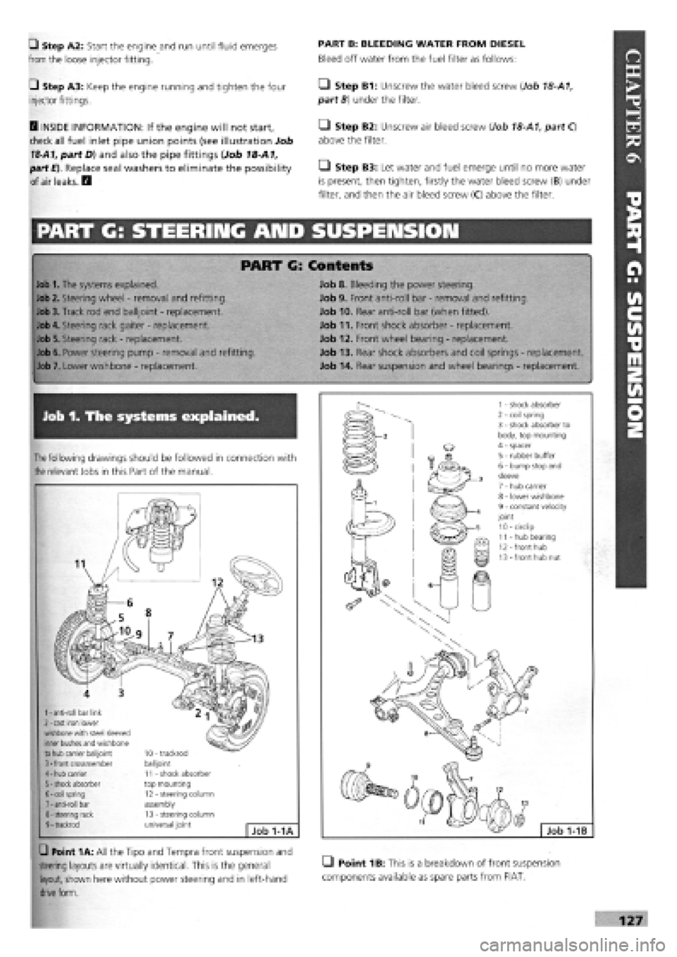
G Point 1A: All the Tipo and Tempra front suspension and
steering layouts are virtually identical. This is the general LI Point 1B: This is a breakdown of front suspension
layout, shown here without power steering and in left-hand components available as spare parts from FIAT,
drive
form.
Page 124 of 171

Job 2. Steering wheel - removal
and refitting.
1 - coil spring 2 - trailing arm 3 - rubber bump stops 4 - handbrake cable 5 - axle beam
6 - anti-roll bar 7 - rear brake regulator 8 - shock absorber 9 - trailing arm hinge bolt
Job 1-1C
SAFETY FIRST!
• AIR BAGS. Because of the safety hazards, both
mechanical and chemical (the air bag contains an
explosive device)
-
we strongly recommend that a car
with an air bag fitted to its steering wheel should be
taken to a FIAT dealer to have its steering wheel
removed and refitted under controlled conditions.
STEERING WHEELS WITHOUT AIR BAGS ONLY
Q Point 1C: The rear suspension design shown here is
common to both Tipo and Tempra.
1 - beam axle 2 - rubber buffer pads 3 - shock absorber top bolt 4 - coil spring 5 - shock absorber 6 - bottom nut and bolt securing shock absorber to trailing arm 7 - trailing arm 8 - anti-roll bar 9 - nut and bolt securing trailing arm to beam axle 10 - stub axle/hub nut 11 - wheel hub 12 - stub axle 13
-
hub cap
Job 1-1D
Q Point 1D: This exploded drawing of the rear suspension
gives a clear view of how several of the assemblies are fitted.
• Step 3: Slacken the lock nut
(arrowed) on the track rod by just enough
to free the balljoint, but no
more.
• Step 4: Now undo the
balljoint to steering arm nut
until the bottom of the nut is
level with the end of the thread.
Job
3-3
Job 3. Track rod end balljoint -
replacement.
Q Step 1: Slacken the roadwheel nuts
on the side to be worked.
Q Step 2: Jack up and support the car
on axle stands and remove the road
wheel.
• Step 1: Undo the wheel
cover fixing bolts (positions
arrowed) from underneath.
• Step 2: Using a ring
spanner or socket and
supporting the wheel with the
other hand (see illustration
Job
2-1),
undo the centre
fixing nut and remove the
steering wheel.
H INSIDE INFORMATION!
Never use the steering column lock to stop the wheel
turning when removing and refitting the centre nut-this
could cause damage and would be a costly mistake. H
• Step 3: Refit in reverse order, tightening the fixing nut to
its specified torque. See Chapter
3,
Facts and Figures.
Page 127 of 171

Q Step 4: Re-assemble in the reverse order using torque
settings shown in Chapter
3,
Facts and Figures
Job 8. Bleeding the power
steering.
The power assisted steering system is self-bleeding. You
should slowly apply full lock alternately to the right and left
with the car stationary and the engine running, while an
assistant tops up the reservoir. This operation should be
carried out each time the connecting pipes are removed or
refitted.
Job 9. Front anti-roll bar -
removal and refitting.
G Step 1: Take note of the components shown here.
G Step 2: Support the car on axle stands and remove the
front wheels for access.
G Step 3: Undo the nuts at the bottom of the anti-roll links
(see illustration Job
9-1,
part 4).
G Step 4: Undo the four bolts securing the two mounting
brackets (Job
9-1,
part 8) and remove the anti-roll bar.
G Step 5: Before refitting, check the condition of the
rubber mounting blocks and bushes and replace if necessary.
Q INSIDE INFORMATION! The washers (Job
9-1,
part 6)
must be fitted with their convex side facing the rubber
bush (part 7). B
lob 10. Rear anti-roll bar (when
fitted).
• Step 3: Undo the three mounting bolts from each side
(see illustration Job
1-1D)
and wriggle the anti-roll bar from
under the car.
• Step 4: Check the anti-roll bar for obvious distortion or
corrosion and the bushes for deterioration. Replace if
necessary.
I—J Step 5: Refit in reverse order.
Job 11. Front shock absorber -
replacement.
Q Step 1: Slacken the bolts of the relevant front wheel,
then raise the front of the car and support on axle stands, so
that the front wheels hang free. See Chapter
1,
Safety First!
Q Step 2: Remove the relevant wheel then detach the brake
hose from the suspension strut bracket.
• Step 3: Remove
the two bolts
('spannered' and
arrowed) which
secure the hub carrier
to the base of the
shock absorber and
separate them.
• Step 4: Working
under-bonnet, undo
the three bolts
('spannered' and
arrowed) securing the
top mounting to the
bodywork turret.
• Step 5: Lower
the suspension strut
to the ground.
• Step 6: Using two coil
spring compressors spread
over as many spring coils as
possible, compress the spring,
tightening each compressor a
little at a time, in turn, until
the spring ends are free of
their seats.
• Because of the irregular shape of the top end of the
spring coils, it can be difficult to use spring
compressors safely.
• We recommend having this work carried out by your
FIAT agent with the correct compressing tool. G Step 1: Support the rear of the car on axle stands.
Job 9-1
1
-
anti-roll bar 2
-
mounting bracket (2 off) 3
-
front crossmember 4
-
anti-roll bar link rod
(2
off) 5
-
lower wishbone 6
-
washer 7
-
rubber bush 8
-
mounting bracket bolt (4 off)
G Step 2: Remove the fuel tank as described in PART
F:
FUEL
AND EXHAUST, Job 10
• Step 7: B INSIDE INFORMATION! Special tool, FIAT
no. 1857509000 is required together with another tool,
no. 1874551000 in order to prevent the centre rod from