1988 FIAT TEMPRA four wheel drive
[x] Cancel search: four wheel drivePage 4 of 171

and explosions. Do not allow resin or 2-pack adhesive hardener,
or that supplied with filler or 2-pack stopper, to come into
contact with skin or eyes. Read carefully the safety notes
supplied on the can, tube or packaging and always wear
impervious gloves and goggles when working with them.
Fluoroelastomers
Fluoroelastomers are commonly used for oil seals, wiring and
cabling, bearing surfaces, gaskets, diaphragms, hoses and '0'
rings. If they are subjected to temperatures greater than 315
degrees C, they will decompose and can be potentially
hazardous. Some decomposition may occur at temperatures
above 200 degrees C, and it is obvious that when a car has
been in a fire or has been dismantled with the assistance of a
cutting torch or blow torch, the fluoroelastomers can
decompose in the manner indicated above.
According to the Health and Safety Executive, "Skin contact
with this liquid or decomposition residues can cause painful and
penetrating burns. Permanent irreversible skin and tissue
damage can occur". Damage can also be caused to eyes or by
the inhalation of fumes created as fluoroelastomers are burned
or heated.
After a vehicle has been exposed to fire or high temperatures:
1. Do not touch blackened or charred seals or equipment.
2. Preferably, don't handle parts containing decomposed
fluoroelastomers, but if you must, wear goggles and PVC
(polyvinyl chloride) or neoprene protective gloves whilst doing
so. Never handle such parts unless they are completely cool.
3. Contaminated parts, residues, materials and clothing,
including protective clothing and gloves, should be disposed of
by an approved contractor to landfill or by incineration
according to national or local regulations. Oil seals, gaskets and
'0' rings, along with contaminated material, must not
be burned.
1. Always have a fire extinguisher of the correct type at arm's
length when working on the fuel system. If you do have a fire,
DON'T PANIC. Use the extinguisher effectively by directing it at
the base of the fire.
2. NEVER use a naked flame anywhere in the workplace.
3. KEEP your inspection lamp well away from any source of
petrol (gasoline) such as when disconnecting a carburettor float
bowl or fuel line.
4. NEVER use petrol (gasoline) to clean parts. Use paraffin
(kerosene), white spirits, or, a proprietary degreaser.
5. NO SMOKING. There's a risk of fire or of transferring
dangerous substances to your mouth and, in any case, ash
falling into mechanical components is to be avoided.
FACT FILE: FOUR WHEEL DRIVE CARS
• Whenever you have to raise a wheel off the
ground and turn it by hand, always ensure that
the opposite-side's wheel to the one being lifted is
also off the ground and free to turn and that both wheels remaining
on the ground are held by the parking brake (if possible) and
securely chocked in both directions.
• ALWAYS have the gearbox in neutral (or 'N' in the case of
automatics). In the case of
some
4 wheel drive automatics and those
with permanent 4WD, it is necessary to disengage the 4WD system
by special means.
• Consult your handbook or seek advice from your main dealer.
6. BE METHODICAL in everything you do, use common sense,
and think of safety at all times.
ENVIRONMENT FIRST!
The used oil from the sump of
just
one car
can
cover
an
area of
water the size of two football pitches, cutting off the oxygen
supply
and
harming swans, ducks, fish and other river lift.
When you drain your engine oil
-
don't oil the drain!
Pouring oil
down the
drain will
cause
pollution. It is
also an
offense.
Don't mix used
oil with other
materials, such
as paint and
solvents,
because this
makes
recycling
difficult.
Take used oil
to an oil
recycling bank.
Telephone
FREE on 0800 663366 to find the location of your nearest oil
bank, or contact you local authority recycling officer.
OIL POLLUTES WATER
USE YOUR BRAIN-
NOT THE DRAIN!
Page 34 of 171

ruvj
uivjh I
uuluj
^ Use a magnetic screw-
driver or place some thick
grease on the end of the
screwdriver to prevent the screws from falling
-
especially when replacing the lens.
7H. Undo screws (A) and (B), pull out the light unit (D) and
undo the connector (E). The height of the beam can later be
adjusted with screw (C).
71. Alternatively: Work from under the front of the car, leaving
the unit in place.
Undo the four screws holding the cover in place. Note that
you do not need to remove the electrical connection from the
cover. On one version of these lights, you have to release the
ends of the spring clips (B) and swing them back to remove
the bulb.
7J. On another version,
you unhook the bulb
retainer (G), remove
the bulb and
disconnect the bulb
cable (L). When
refitting, ensure that
the cut-out in the bulb
base-plate (H) is
located correctly.
REAR LIGHTS
-
TIPO
7K. Open the
hatchback door and
remove the three
screws (arrowed)
holding the lens in
place.
7L. From the inner side
of the light unit, take
out the two screws
(arrowed) holding the
lens to the unit. Take
care not to strain the
wiring.
7M. These are the positions of the bulbs. All of the bulbs are
released by pushing in slightly, turning anti-clockwise and
pulling out when free.
REAR LIGHTS -
TEMPRA
SALOON
7N. Open the boot
lid and remove the
screw (F).
-fog light bulb (21W)
70
70. Lift the lens away. The bulbs are removed as described in
7M.
REAR LIGHTS
-
TEMPRA ESTATE
7P. Open the
tailgate door and
remove the two
screws (A).
From inside the
car, remove the
spare wheel, if
fitted, open the
side compartment and remove its covers. Unscrew the knurled
nut (A) which fits on to the captive screw (B) mounted on the
lens. Use your other hand to prevent the lens from falling.
Now, pull off the lens and remove the two knurled nuts (C) to
give you access to the bulb holder.
A - tail-light
bulb (5W)
B - stop light
bulb (21W)
C - direction
indicator bulb
(21W)
D - reversing light bulb (21W) E
A - reversing
bulb (21W)
B - direction
indicator bulb (21W)
C - stop light bulb
(21W)
D
-
tail-light bulb
(5W)
E - fog light bulb
(21W)
Page 55 of 171

REAR SHOCK ABSORBERS • Job 48. Check wheel bolts for tightness.
Look for signs of leaks coming from underneath the top part
of
each
rear shock absorber and replace if necessary. Check
the
top and bottom rubber mounting bushes. If any are soft
or
split they must be replaced. Check that the bump stops are
present and correct.
BOUNCE TEST: Bounce-test the shock absorbers as in Job 43.
PART G: BRAKING SYSTEM
SAFETY FIRST!
• Job 49. Check front brakes.
You can
check the thickness of the brake pads by looking
through
the 'window' in the caliper. However, this isn't
recommended
unless you are experienced and know what you
are looking for,
and you can't check the caliper or clean out
accumulated
brake dust.
• Before raising the car, see Chapter 1, Safety First!
•
Also,
be sure to read the section on BRAKES AND
ASBESTOS in Chapter 1, Safety First! for further
important
information.
•
Your car's
brakes are its most important
safety-
related items.
Do NOT attempt any work on the
braking system unless
you are fully competent to do so.
• If you have not been trained in this work, but wish
to
carry
it out, we strongly recommend you have a
garage
or qualified mechanic check your work before
using
the car on the road.
•
Always
start by washing the brakes with a propri-
etary
brand of brake cleaner
-
brake drums removed
where
appropriate
-
and never use compressed air to
clean
off
brake
dust.
•
Always
replace brake pads and/or shoes in complete
'axle' sets
of four
-
never replace them on one wheel
only.
• After fitting new brake shoes or pads, avoid heavy
braking
for the first
150
to 200 miles (250 to 300 km),
except
in
an emergency.
49B. This
drawing
illustrates the
various
components of
the front brake
assembly.
49C. Remove the
bottom caliper bolt,
using an open-ended
spanner to allow the
bolt to turn. ALWAYS
refit with NEW FIAT
caliper mounting bolts
-
they are a special
type.
Therefore,
checking the Tipo's and Tempra's brake pads
involves
the same amount of work as changing them. For that
reason, brake
pad replacement is covered here in detail rather
than in
Chapter
6,
Repairs and Replacements.
49A. Start by raising
the
wheel to
be
worked on and
supporting it on
an
axle stand. Remove
the road wheel
-
see
Chapter
1, Safety
First!
Compare the thickness of the two pads
-
there should be no
significant difference. The minimum recommended thickness
of lining material is 1.5 mm, but bearing in mind the amount
of time before the next service, you may wish to replace the
pads before they get to this stage.
You can now check the thickness of the brake disc, which
should not be below the figure given for your model in
Chapter
3,
Facts and Figures, at any point.
Remove each wheel
bolt in turn and
ensure that they run
smoothly. Clean the
threads, if necessary.
Refit and check that all
are tightened to the
correct torque
-
see
Chapter
3,
Facts and
Figures
-
using a torque wrench.
49D. Slacken the top
bolt, swivel the caliper
up and the pads come
free, for checking.
IMPORTANT NOTE:
If you remove the
top caliper bolt, DO NOT allow the weight of the caliper
to hang from the flexible hose
-
position it to rest on the
driveshaft, or support it from the road spring using a
length of wire.
Page 61 of 171

PART A: ENGINE
PART A: Contents
Job 1. Petrol engine. Timing belt
-
replacement and Job 12. Petrol engine. Mountings
-
replacement.
adjustment. Job 13. Diesel engine. Timing belt
-
replacement and
Job 2. Petrol engine. Cylinder head
-
removal. adjustment. •
Job 3. Petrol engine. Cylinder head and camshaft housing -Job 14. Diesel engine. Cylinder head
-
removal.
refitting. Job 15. Diesel engine. Cylinder head
-
refitting.
Job
4.
Petrol engine. Cylinder head
-
dismantling and Job 16. Diesel engine. Cylinder head
-
overhaul.
overhauling. Job 17. Diesel engine. Valve clearances
-
adjustment.
Job 5. Petrol engine
-
dismantling. Job 18. Diesel engine
-
removal.
Job
6.
Petrol engine
-
checking and reassembly. Job 19. Diesel engine
-
refitting.
Job
7.
Petrol engine. Valve clearances
-
adjustment. Job 20. Diesel engine. Mountings
-
replacement.
Job 8. Petrol engine/transmission
-
removal. Job 21. Diesel engine/transmission (removed from car)
-
Job
9.
Petrol engine/transmission
-
refitting. separation.
Job 10. Petrol engine/transmission (removed from car)
-
Job 22. Diesel engine/transmission (removed from car)
-
separation. reconnection.
Job 11. Petrol engine/transmission (removed from car)
-
Job 23. Diesel engine
-
dismantling.
reconnection. Job 24. Diesel engine
-
reassembly.
Job 1. Petrol engine. Timing belt
- replacement and adjustment.
Mi*^^ Zc+sc, / • The crankshaft pulley nut
n^^ will be difficult to turn.
• If the engine is in the car,
engage a gear (or 'Park' in the case of an automatic)
and have an assistant hold the footbrake down very
firmly. This will stop the engine from turning.
• Alternatively, with the starter motor removed, you
can have a helper prevent the flywheel ring gear from
turning with a large screwdriver.
• Step 4: Before removing the belt, put the pulley nut back
onto the crankshaft, take the car out of gear (if the engine is
still in the car) and remove the spark plugs. You can now turn
the engine in a clockwise direction using the refitted crank
pulley nut
-
without the pulley, of course!
• Step 5A: With
the timing belt still in
place, turn the engine
so that the timing
mark on the camshaft
sprocket lines up with
the one on the front
cover. On some
engines, the front
cover looks like this...
• Step 5B:
...while on the
majority, it looks
like this. The top
part of the cover
backplate slides
out so that the
plastic pip is level
with the camshaft
sprocket. Turn
the sprocket so that the timing mark on the sprocket lines up
with this pip.
IMPORTANT NOTE: It is false economy to refit a used
timing belt. If the belt breaks, it will cause complete
engine failure so always fit a new one.
• Step 1:
Disconnect the battery
and
remove the
alternator drivebelt as
described in PART C:
COOLING
SYSTEM
0 Step 2: Take off
the timing
belt cover.
This is held
by a total
of
four bolts (arrowed).
• Step 3: Take off
the
crankshaft pulley
nut and
remove the
pulley.
Page 123 of 171
• Step A2: Start the engine and run until fluid emerges
from the loose injector fitting.
G Step A3: Keep the engine running and tighten the four
injector fittings.
B INSIDE INFORMATION: If the engine will not start,
check all fuel inlet pipe union points (see illustration Job
18-A1,
part D) and also the pipe fittings (Job 18-A1,
part E). Replace seal washers to eliminate the possibility
of air leaks. H
PART B: BLEEDING WATER FROM DIESEL
Bleed off water from the fuel filter as follows:
• Step B1: Unscrew the water bleed screw (Job 18-A1,
part B) under the filter.
• Step B2: Unscrew air bleed screw (Job 18-A1, part Q
above the filter.
• Step B3: Let water and fuel emerge until no more water
is present, then tighten, firstly the water bleed screw (B) under
filter, and then the air bleed screw (C) above the filter.
PART G: STEERING AND SUSPENSION
PART G: Contents
Job
1.
The systems explained.
Job
2.
Steering wheel
-
removal and refitting
Job 3. Track rod end balijoint
-
replacement.
Job
4.
Steering rack gaiter
-
replacement.
Job 5. Steering rack
-
replacement.
Job
6.
Power steering pump
-
removal and refitting
Job
7.
Lower wishbone
-
replacement.
Job 8. Bleeding the power steering.
Job 9. Front anti-roll bar
-
removal and refitting.
Job 10. Rear anti-roll bar (when fitted).
Job 11. Front shock absorber
-
replacement.
Job 12. Front wheel bearing
-
replacement.
Job 13. Rear shock absorbers and coil springs
-
replacement.
Job 14. Rear suspension and wheel bearings
-
replacement.
Job 1. The systems explained.
The
following drawings should be followed in connection with
the
relevant Jobs in this Part of the manual.
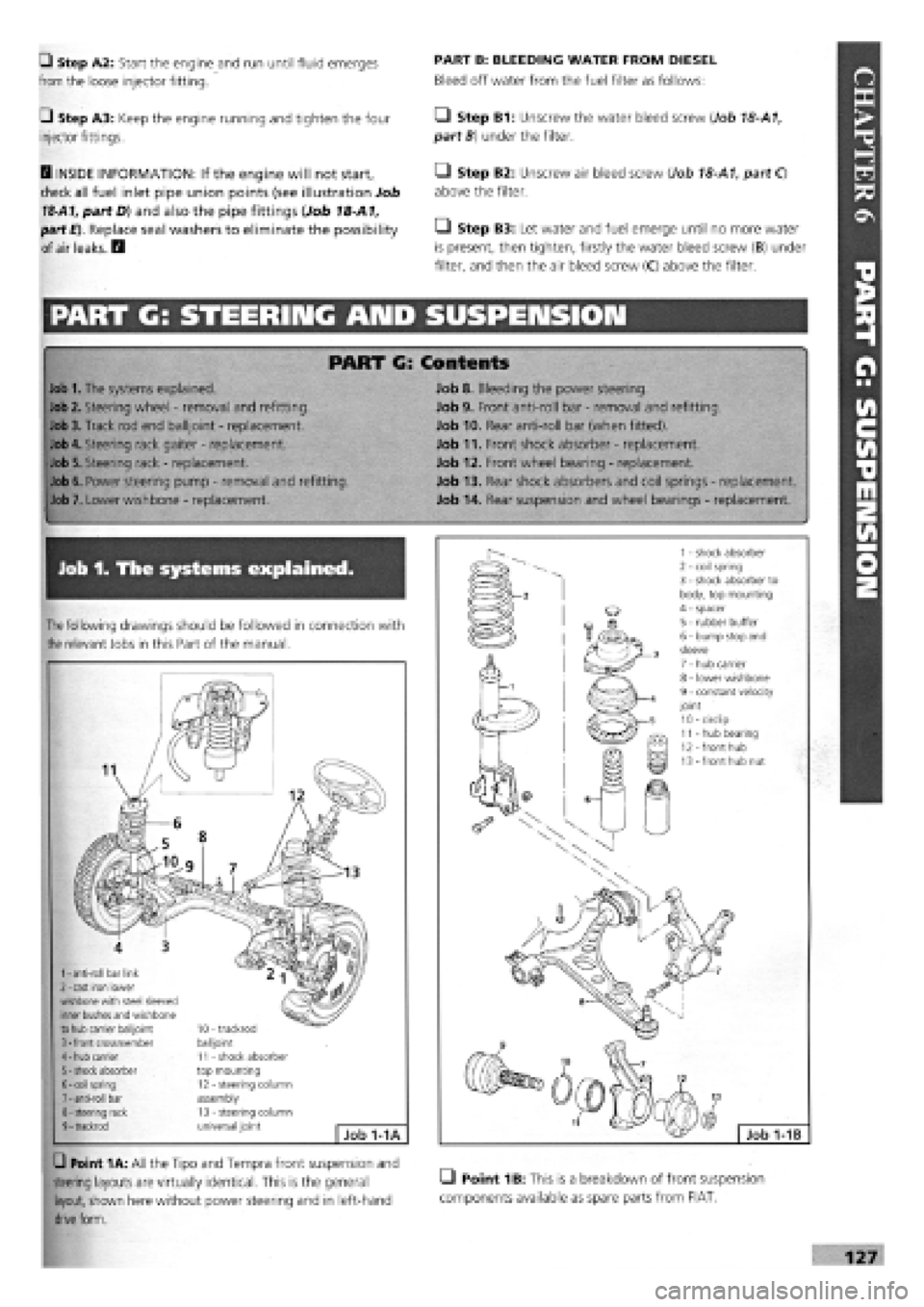
1
-
anti-roll bar link 2
-
cast iron lower wishbone with steel sleeved inner bushes and wishbone to hub carrier balijoint 3
-
front crossmember 4
-
hub carrier 5
-
shock absorber 6
-
coil spring 7
-
anti-roll bar 8
-
steering rack 9
-
trackrod
10 - trackrod balijoint 11 - shock absorber top mounting 12 - steering column assembly 13 - steering column universal joint Job 1-1A
G Point 1A: All the Tipo and Tempra front suspension and
steering layouts are virtually identical. This is the general LI Point 1B: This is a breakdown of front suspension
layout, shown here without power steering and in left-hand components available as spare parts from FIAT,
drive
form.
Page 126 of 171
Q Step A9: Place the steering wheel in the dead ahead
position and engage the rack pinion splines with the column
coupling.
Q Step A10: Continue refitting in the reverse order of
removal.
• Step A11: Take your car to your nearest FIAT dealership
or tyre specialist to have the front wheel alignment set before
using the car further. This is NOT a job you can do at home
but is DOES need doing as soon as possible to avoid severe
tyre wear and dangerous braking and steering!
PART B: POWER STEERING RACK
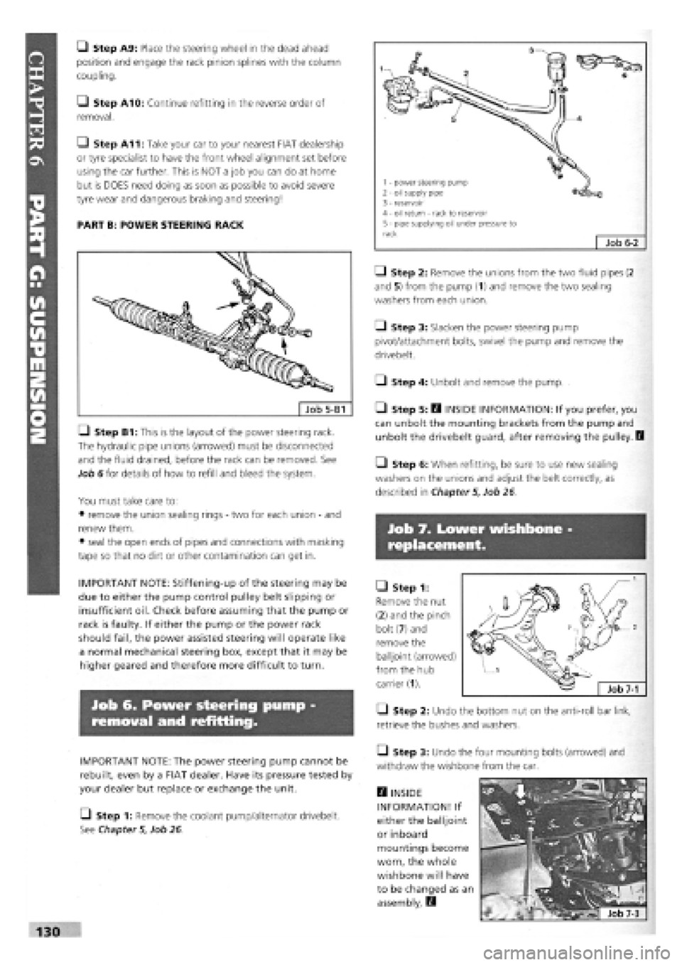
LI Step B1: This is the layout of the power steering rack.
The hydraulic pipe unions (arrowed) must be disconnected
and the fluid drained, before the rack can be removed. See
Job 6 for details of how to refill and bleed the system.
You must take care to:
• remove the union sealing rings
-
two for each union
-
and
renew them.
• seal the open ends of pipes and connections with masking
tape so that no dirt or other contamination can get in.
IMPORTANT NOTE: Stiffening-up of the steering may be
due to either the pump control pulley belt slipping or
insufficient oil. Check before assuming that the pump or
rack is faulty. If either the pump or the power rack
should fail, the power assisted steering will operate like
a normal mechanical steering box, except that it may be
higher geared and therefore more difficult to turn.
Job 6. Power steering pump
removal and refitting.
IMPORTANT NOTE: The power steering pump cannot be
rebuilt, even by a FIAT dealer. Have its pressure tested by
your dealer but replace or exchange the unit.
[_) Step 1: Remove the coolant pump/alternator drivebelt.
See Chapter
5,
Job 26.
• Step 2: Remove the unions from the two fluid pipes (2
and 5) from the pump (1) and remove the two sealing
washers from each union.
Q Step 3: Slacken the power steering pump
pivot/attachment bolts, swivel the pump and remove the
drivebelt.
• Step 4: Unbolt and remove the pump.
• Step 5: B INSIDE INFORMATION: If you prefer, you
can unbolt the mounting brackets from the pump and
unbolt the drivebelt guard, after removing the pulley. I
• Step 6: When refitting, be sure to use new sealing
washers on the unions and adjust the belt correctly, as
described in Chapter
5,
Job 26
Job 7. Lower wishbone
replacement.
• Step 1:
Remove the nut
(2) and the pinch
bolt (7) and
remove the
balljoint (arrowed)
from the hub
carrier (1).
• Step 2: Undo the bottom nut on the anti-roll bar link,
retrieve the bushes and washers.
• Step 3: Undo the four mounting bolts (arrowed) and
withdraw the wishbone from the car.
H INSIDE
INFORMATION! If
either the balljoint
or inboard
mountings become
worn, the whole
wishbone will have
to be changed as an
assembly. E3
130
1 - power steering pump 2 - oil supply pipe 3 - reservoir 4 - oil return - rack to reservoir 5 - pipe supplying oil under pressure to rack Job
6-2
Page 130 of 171

• Step 8:
Support the
axle beam with
the jack and
undo the
mounting bolts
(arrowed and
indicated by
operator with
socket bar).
Lower the
complete unit
from the car.
IMPORTANT NOTE: In this shot, the top shock absorber
mountings have been disconnected, leaving the shock
absorber fitted to the suspension and the coil springs in
place. We recommend 'our' approach, covered in Step 7!
• Step 9: Undo the bolts securing the anti-roll bar and
remove it. (See Job 9.) Disconnect the brake pipes from the
side to be worked on and remove the brake drum.
Q Step 10: Remove the hub cap (see illustration Job 1-1D,
part 13) by carefully tapping and levering with a screwdriver.
• Step 11: Undo the hub nut (see illustration Job 1-1D,
part
10).
PART H: BRAKES
• Step 12: A special tool
(1857508000) or a VERY
strong Allen key (a) will be
required to reach into the
hub (b), and plenty of
leverage!
Q Step 13: Remove the
hub and inspect the bearing
for roughness or noise or
roughness when turning it by hand.
E3 INSIDE INFORMATION! The bearing is lubricated for
life and is only supplied as an assembly with the hub. B
• Step 14: Inspect the stub axle pin (see illustration Job
1-
1D, part
12)
for any signs of damage or distortion. Replace if
in doubt.
Q Step 15: Refitting is the reverse of removal but note the
following:
• See Chapter
3,
Facts and Figures for all tightening
torques as you progress through the assembling.
• Use new hub nuts and fully tighten once the suspension is
mounted to give you stability.
• Refer to PART H: BRAKES when refitting the brake parts
and bleeding the brakes.
PART H: Contents %
Job 1. Understanding Tipo/Tempra brakes.
Job 2. Front brake pads
-
replacement.
Job 3. Front brake caliper
-
replacement.
Job 4. Front brake disc
-
replacement.
Job 5. Rear brake shoes
-
replacement.
Job 6. Rear wheel cylinder
-
replacement.
Job 7. Rear brake disc pads
-
replacement.
Job 8. Rear brake caliper
-
replacement.
Job 9. Rear brake disc
-
replacement.
Job 10. Master cylinder
-
replacement.
Job 11. Servo check
-
remove and refit.
Job 12. Pressure regulating valve, non-ABS system -
replacement and adjustment.
Job 13. Pressure regulating valves, ABS system
-
replacement
and adjustment.
Job 14. RPM sensors, ABS systems
-
replacement.
Job 15. Flexible hoses
-
replacement.
Job 16. Metal pipes
-
replacement.
Job 17. Brake bleeding.
Job 18. Handbrake cables
-
replacement.
Job 1. Understanding
Tipo/Tempra brakes.
• Point
1
A: This is the standard disc/drum system used on
cars without anti-lock brakes, shown here in left hand drive
form.
1 - fluid reservoir and master cylinder 2 - servo 3
-
front disc brakes
4 - handbrake lever 5 - rear drum brakes 6
-
four way pipe union 7 - load proportioning/ pressure limiting valve
Job 1-1A
1 - front disc brakes 2
-
front flywheel 3 - front wheel RPM sensors 4 - hydraulic control unit 5 - brake light switch 6 - device failure warning light switch
7 - rear flywheel 8 - main control relay with excess voltage protection 9 - electronic control unit 10 - rear disc brakes 11 - rear wheel RPM sensors 12 - load proportioning/pressure limiting valve Job
1-1B