Page 194 of 513
J
J
CD
11
BODY
I
K
L
L
N
N
@
r
T
I
c
cb
I
cp
M
M
J
Ii
0
0
SEALING
ON
CIRCUMFERENCE
OF
REAR
FLOOR
@
Ii
DETAILS
OF
Q
PORTION
DETAILS
OF
R
PORTION
1
Rear
floor
2
Rear
fender
3
Luggage
compartment
floor
rear
side
4
Front
pillar
5
Front
fender
6
Ou
tee
door
7
Fue
filler
cover
8
Shock
absorber
mount
bracket
9
Seat
back
support
10
Inner
lock
pillar
11
Lock
pillar
12
Roof
13
Rear
waist
14
Luggage
compartment
lid
15
Rear
panel
16
Outer
wheel
house
Fig
BF
6
Cross
sectional
view
II
BF
4
Page 195 of 513
COUPE
BODY
T
@
T
v
v
vv
l
2
DOOR
1
5
Vv
t
t
tJ
DETAILS
OF
8
PORTION
1
r
I
A
A
J
C
C
j
@
cr
U
D
D
@
DETAILS
OF
E
PORTION
1
Roof
2
Inner
side
body
3
Rear
fender
4
Outer
door
5
Front
pillar
6
Front
fender
7
loner
wheel
house
8
Rear
floor
9
I
Rner
lock
pilla
c
to
Lock
pillar
Fig
BF
7
Cross
sectional
view
III
SF
5
Page 204 of 513

BODY
HOOD
CONTENTS
REMOVAL
AND
INSTAllATION
Removal
Installation
SF
14
SF
14
SF
14
REMOVAL
AND
INSTALLATION
Removal
Disconnect
the
windshield
washer
hose
at
the
nozzle
2
In
order
to
protect
the
hood
from
damaging
place
rag
in
both
sides
of
the
hood
rear
end
loosen
the
hood
hinge
installation
bolts
and
remove
the
hood
supporting
it
from
both
sides
as
shown
in
the
following
figure
Two
workers
are
required
Fig
BF
16
Removing
hood
hinge
I
i
7
r
r
o
r
il
Zc
h
2
Fig
BF
17
Remvoing
hood
HOOD
lOCK
Removal
Adjustment
Lubrication
Installation
SF
14
SF
14
SF
15
SF
16
Install
the
hood
in
reverse
sequence
of
removal
carefully
so
that
the
hood
is
flush
with
the
fender
top
and
clearance
between
the
hood
and
fender
is
aligned
evenly
toward
overall
circumferenc
e
of
the
hood
when
the
hood
is
closed
HOOD
LOCK
@
OJ
d
@
Q
o
1
Dovetail
bolt
2
Dovetail
bolt
retaining
nut
3
Spring
4
Safety
catch
lever
5
Female
lever
6
Spring
7
Hood
lock
control
lever
8
Rubber
grommet
Fig
BF
18
Hood
lock
mechanism
Removal
I
Remove
the
radiator
grille
loosen
the
installation
bolts
and
remove
the
male
side
of
the
hood
lock
2
Disconnect
the
hood
lock
wire
from
the
female
side
of
the
hood
lock
and
remOve
the
female
side
of
the
hood
lock
BF
14
Page 205 of 513

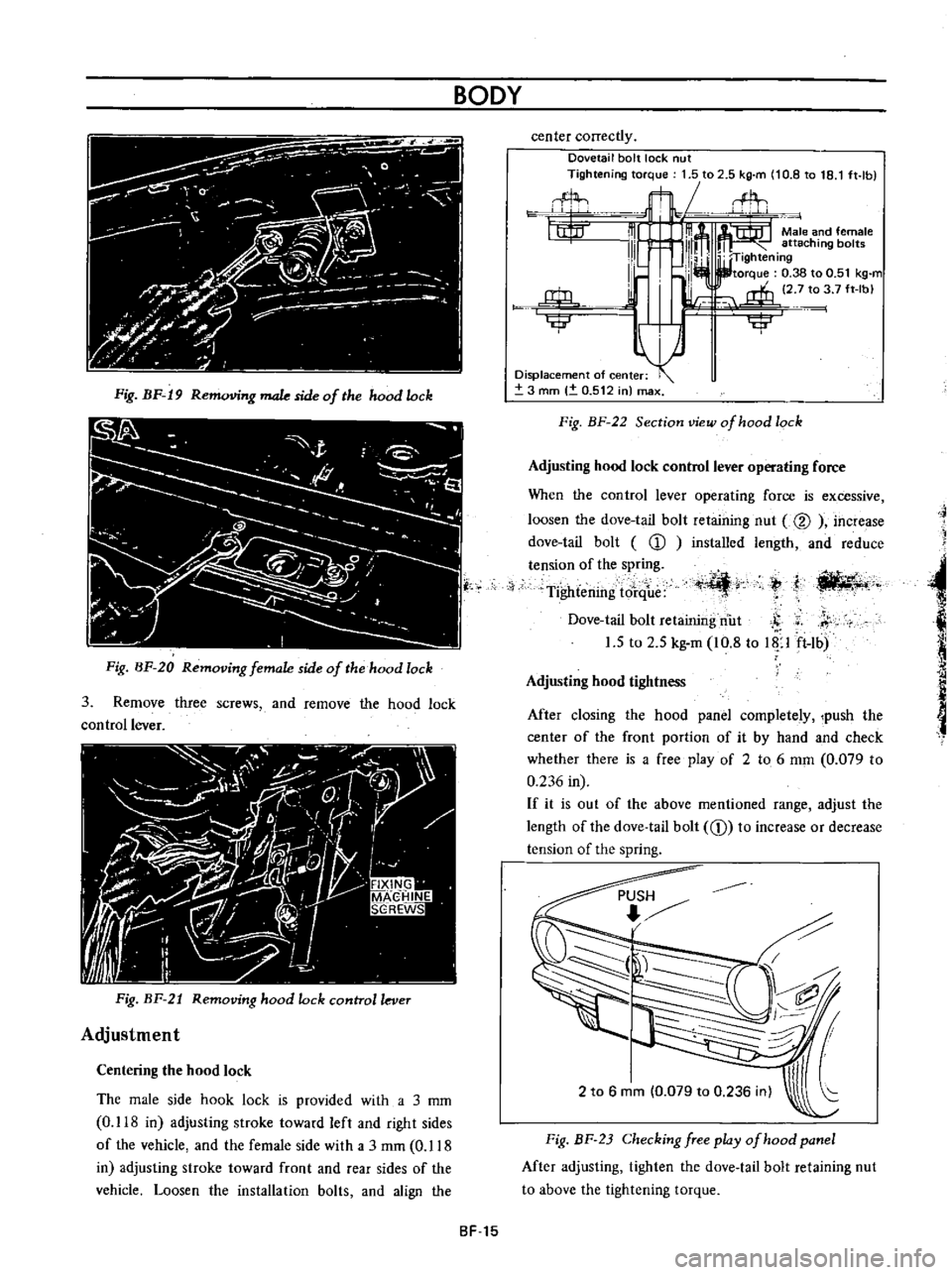
BODY
Fig
BF
19
R
g
male
side
of
the
hood
lock
Fig
BF
20
Removing
female
side
of
the
hood
lock
3
Remove
three
screws
and
remove
the
hood
lock
control
lever
Fig
BF
21
Removing
hood
lock
control
lever
Adjustment
Centering
the
hood
lock
The
male
side
hook
lock
is
provided
with
a
3
mm
0
118
in
adjusting
stroke
toward
left
and
right
sides
of
the
vehicle
and
the
female
side
with
a
3
rnm
0
118
in
adjusting
stroke
toward
front
and
rear
sides
of
the
vehicle
Loosen
the
installation
bolts
and
align
the
center
correctly
Dovetail
bolt
lock
nut
Tightening
torque
1
5
to
2
5
kg
m
10
8
to
18
1
ft
lb
flL
t1t
m
m
Male
and
female
111
l
111m
attaching
bol
W
TIghtening
I
lb
I
I
torque
0
38
to
0
51
kg
m
l
i
2
7
to
3
7
ft
Ibl
j
rffi
u
Ilillr
iji
Displacement
of
center
3
mm
0
512
in
max
Fig
BF
22
Section
view
of
hood
lock
Adjusting
hood
lock
control
lever
operating
force
When
the
control
lever
operating
force
is
excessive
loosen
the
dove
tail
bolt
retaining
nut
@
increase
dove
tail
bolt
CD
installed
length
and
reduce
tension
of
the
spring
Tightening
tore
ue
t
I
ili
4r
ti
llt4
t
j
Dove
tail
bolt
retaining
nut
S
r
1
5
to
2
5
kg
m
10
8
to
Up
ft
lb
Adjusting
hood
tightness
After
closing
the
hood
panel
completely
push
the
center
of
the
front
portion
of
it
by
hand
and
check
whether
there
is
a
free
play
of
2
to
6
mm
0
079
to
0
236
in
If
it
is
out
of
the
above
mentioned
range
adjust
the
length
of
the
dove
tail
bolt
CD
to
increase
or
decrease
tension
of
the
spring
2
to
6
mm
0
079
to
0
236
inl
Fig
BF
23
Checking
free
play
of
hood
panel
After
adjusting
tighten
the
dove
tail
bolt
retaining
nut
to
above
the
tightening
torque
SF
15
Page 206 of 513

BODY
Fig
BF
24
Adjusting
dove
tail
bolt
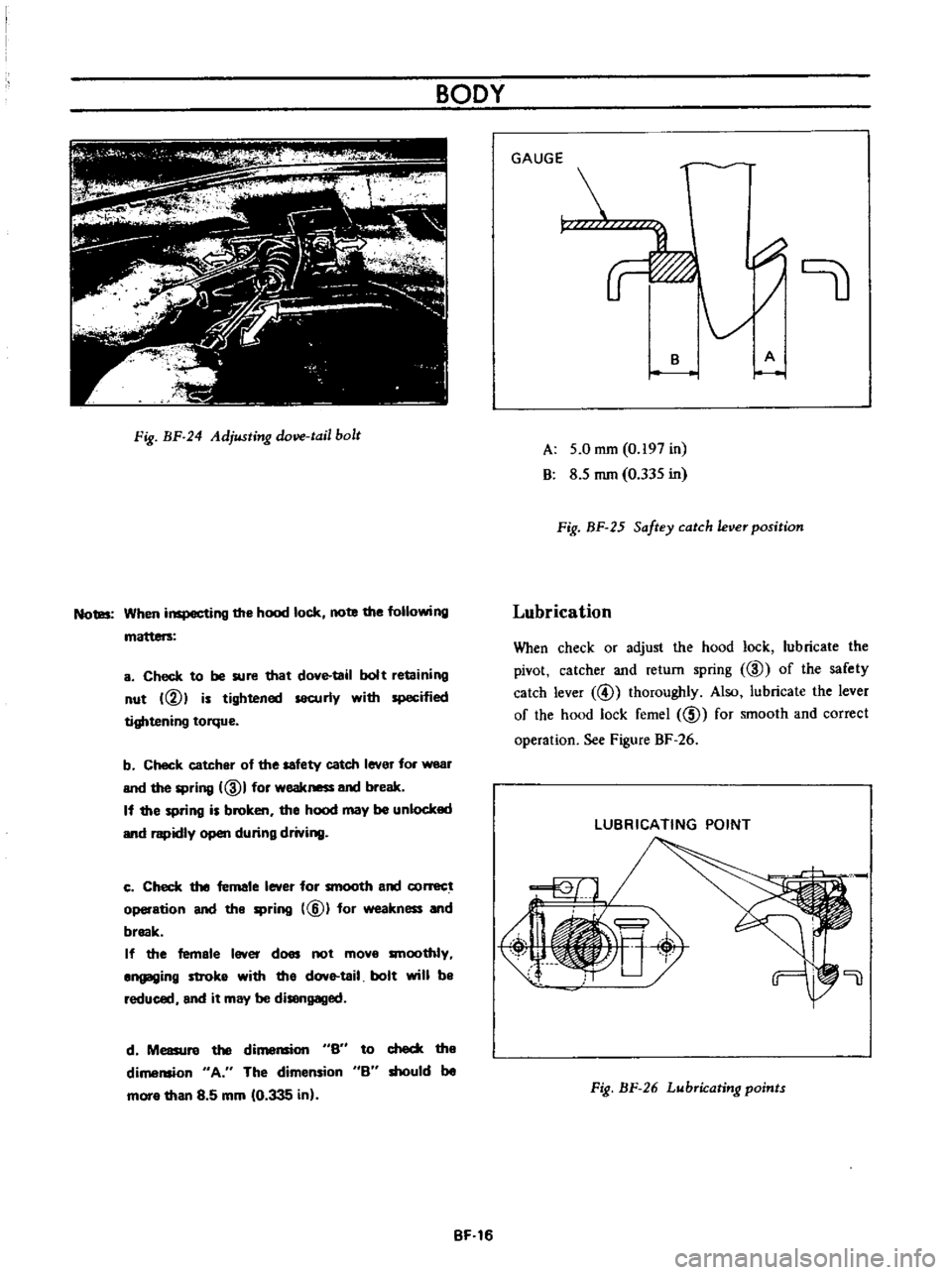
Notes
When
inspecting
the
hood
lock
note
the
following
a
Check
to
be
sure
that
dove
tail
bolt
retaining
nut
VI
is
tightened
securly
with
specified
tightening
torque
b
Check
catcher
of
the
safety
catch
lever
for
wear
and
the
spring
ID
I
for
weakness
and
break
If
the
spring
is
broken
the
hood
may
be
unlocked
and
rapidly
open
during
driving
c
Check
the
female
lever
for
smooth
and
conect
operation
and
the
spring
@
for
weakness
and
break
If
the
female
lever
does
not
mova
smoothly
angaging
stroka
with
tha
dove
tail
bolt
will
ba
reduced
and
it
may
be
disengaged
d
Measure
the
di
S6
to
check
the
dimension
A
The
dimension
B
should
be
mora
than
8
5
mm
10
335
in
BF
16
GAUGE
r
B
A
A
5
0
mm
0
197
in
B
8
5
mm
0
335
in
Fig
BF
25
Saftey
catch
ever
position
Lubrication
When
check
or
adjust
the
hood
lock
lubricate
the
pivot
catcher
and
return
spring
ID
of
the
safety
catch
lever
@
thoroughly
Also
lubricate
the
lever
of
the
hood
lock
femel
ID
for
smooth
and
correct
operation
See
Figure
BF
26
LUBRICATING
POINT
Fig
BF
26
Lubricating
points
Page 209 of 513

BODY
I
1
I
Ik
I
ro
I
W
a
21
zrl
l
11
J
1
3781
I
1
Ii
100
tJ94t
I
100
3
94
0
0551
A
I
10013
94
1
510
0984
100
13
94
I
J
10
1378
2010
787
L
I
l
0
433
O
I
l
JS
348
13
7
5
1
77
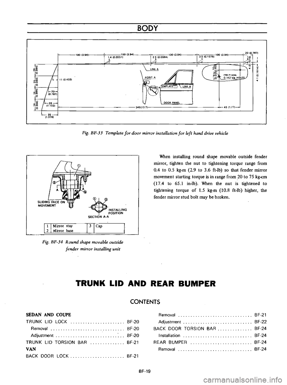
Fig
BF
33
Template
for
door
mirror
installation
for
left
hand
drive
vehicle
INSTALLING
OSITION
SECTION
A
A
When
installing
round
shape
movable
outside
fender
rnirror
tighten
the
nut
to
tightening
torque
range
from
0
4
to
0
5
kg
m
2
9
to
3
6
ft
lb
so
that
fender
rnirror
rnovernent
starting
torque
is
in
range
from
20
to
75
kg
rn
I74
to
65
1
in
lb
When
the
nut
is
tightened
to
tightening
torque
of
1
5
kg
m
10
8
ft
lb
higher
the
fender
mirror
stud
bolt
may
be
broken
Tl4
11
I
Mirror
stay
2
I
Mirror
base
31
Cap
Fig
BF
34
Round
shape
movable
outside
fender
mirror
installing
unit
TRUNK
LID
AND
REAR
BUMPER
CONTENTS
SEDAN
AND
COUPE
TRUNK
LID
LOCK
Removal
Adjustment
TRUNK
LID
TORSION
BAR
VAN
BACK
DOOR
LOCK
BF
20
BF
20
BF
20
BF
21
Removal
Adjustment
BACK
DOOR
TORSION
BAR
Installation
REAR
BUMPER
Removal
BF
21
BF
22
BF
24
BF
24
BF
24
BF
24
BF
21
BF
19
Page 210 of 513

BODY
SEDAN
AND
COUPE
CD
@
h
r
1
@
@
II
I
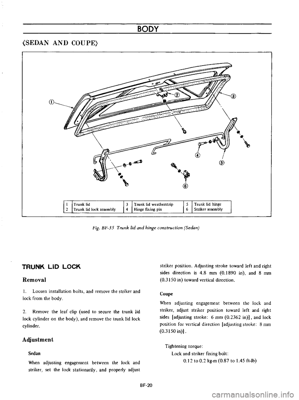
Trunk
lid
2
Trunk
lid
lock
assembly
13
I
Trunk
lid
weatherstrip
4
Hinge
fixing
pin
15
I
Trunk
lid
hinge
6
Striker
assembly
Fig
BF
35
Trunk
lid
and
hinge
construction
Sedan
Removal
striker
position
Adjusting
stroke
toward
left
and
right
sides
direction
is
4
8
mm
0
1890
in
and
8
mm
0
3150
in
toward
vertical
direction
TRUNK
LID
LOCK
1
Loosen
installation
bolts
and
remove
the
striker
and
lock
from
the
body
Coupe
When
adjusting
engagement
between
the
lock
and
striker
adjust
striker
position
toward
left
and
right
sides
adjusting
stroke
6
mm
0
2362
in
and
lock
position
for
vertical
direction
adjusting
stroke
8
mm
0
3150
in
2
Remove
the
leaf
clip
used
to
secure
the
trunk
lid
lock
cylinder
on
the
body
and
remove
the
trunk
lid
lock
cylinder
Adjustment
When
adjusting
engagement
between
the
lock
and
striker
set
the
lock
stationarily
and
properly
adjust
Tightening
torque
Lock
and
striker
fIxing
bolt
0
12
to
0
2
kg
m
0
87
to
I
45
ft
Ib
Sedan
SF
20
Page 211 of 513
BODY
TRUNK
LID
TORSION
BAR
The
procedures
of
installing
torsion
bar
are
indicated
as
follows
ill
ID
f
Jw
V
@
@
Fig
BF
36
Installing
torsion
bar
1
Closed
position
2
Rotation
center
of
trunk
lid
hinge
3
Trunk
lid
hinge
4
Trunk
lid
torsion
bar
5
Rear
waist
connector
Note
When
installing
the
to
ion
bar
use
to
ion
bar
wrench
special
tool
ST087100001
VAN
t
9
@
i
Fig
BF
37
Back
door
and
hinge
constructions
BACK
DOOR
LOCK
1
Back
door
hinge
torsion
bar
2
Back
door
hinge
3
Back
door
4
Back
door
lock
rod
5
Lock
6
Striker
7
Striker
shim
8
Back
door
side
dovetail
9
Side
dovetail
shim
10
Back
door
bumper
11
Back
door
bumper
plate
Removal
2
Remove
the
lock
cylinder
securing
leaf
clip
so
as
to
free
the
lock
cylinder
and
remove
the
back
door
lock
rod
from
the
lock
cylinder
I
Remove
the
back
door
trim
and
sealing
screen
BF
21