1973 DATSUN B110 lock
[x] Cancel search: lockPage 74 of 513
PROPELLER
SHAFT
DIFFERENTIAL
CARRIER
10
Measure
the
initial
turning
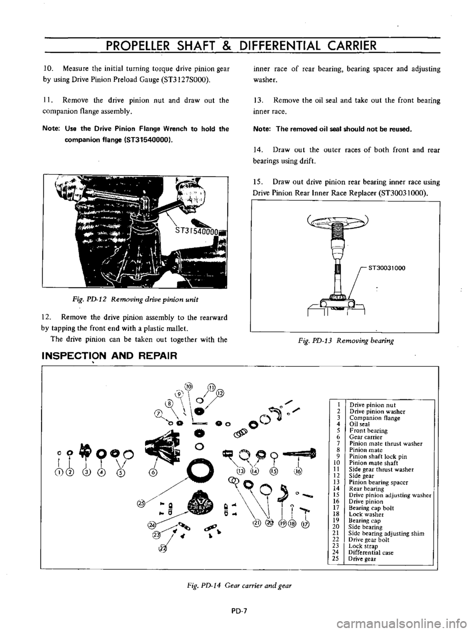
torque
drive
pinion
gear
by
using
Drive
Pinion
Preload
Gauge
Sn127S000
11
Remove
the
drive
pinion
nut
and
draw
out
the
companion
flange
assembly
Note
Use
the
Drive
Pinion
Flange
Wrench
to
hold
the
companion
flange
IST31540000
Fig
PD
12
Removing
drive
pinion
unit
12
Remove
the
drive
pinion
assembly
to
the
rearward
by
tapping
the
front
end
with
a
plastic
mallet
The
drive
pinion
can
be
taken
out
together
with
the
INSPECTION
AND
REPAIR
inner
race
of
rear
bearing
bearing
spacer
and
adjusting
washer
13
Remove
the
oil
seal
and
take
out
the
front
bearing
inner
race
Note
The
removed
oil
seal
should
not
be
reused
14
Draw
out
the
outer
races
of
both
front
and
rear
bearings
using
drift
15
Draw
out
drive
pinion
rear
bearing
inner
race
using
Drive
Pinion
Rear
Inner
Race
Replacer
ST30031000
ST30031
000
AI
n
Fig
PD
13
Removing
bearing
10
y@
@
0
0
0
00
eo
00
j
l
I
@
o
q@
@
t
I
7
c9
@
@@
@
l2
4
o
OO
r
j
T
I
i
cb
3
0
0
Fig
PD
14
Gear
carrier
and
gear
PD
7
1
2
3
4
S
6
7
8
9
10
II
12
IJ
14
IS
16
17
18
19
20
21
22
23
24
25
Drive
pinion
nut
Drive
pinion
washer
Companion
flange
Oil
seal
Front
bearing
Gear
carrier
Pinion
mate
thrust
washer
Pinion
mate
Pinion
shaft
lock
pin
Pinion
mate
shaft
Side
gear
thrust
washer
Side
gear
Pinion
bearing
spacer
Rear
bearing
Drive
pinion
adjusting
washer
o
rive
pinion
Bearing
cap
bolt
Lock
washer
Bearing
cap
Side
bearing
Side
bearing
adjusting
shim
Drive
gear
bolt
Lock
strap
Differential
case
D
rive
gear
Page 76 of 513
PROPELLER
SHAFT
DIFFERENTIAL
CARRIER
Reassemble
the
differential
carrier
in
reverse
order
of
disassembly
The
following
instructions
for
adjustment
and
usage
of
special
tuols
are
essential
to
obtain
perfect
differential
operation
Assembling
differential
gear
case
1
Assemble
the
pinion
mate
side
gear
and
thrust
washer
in
the
differential
case
2
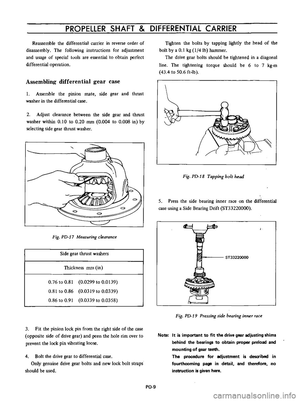
Adjust
clearance
between
the
side
gear
and
thrust
washer
within
0
10
to
0
20
mm
0
004
to
0
008
in
by
selecting
side
gear
thrust
washer
Fig
PD
17
Measuring
clearance
Side
gear
thrust
washers
Thickness
mm
in
0
76
to
0
81
0
0299
to
0
0139
0
81
to
0
86
0
0319
to
0
0339
0
86
to
0
91
0
0339
to
0
0358
3
Fit
the
pinion
lock
pin
from
the
right
side
of
the
case
opposite
side
of
drive
gear
and
peen
the
hole
rim
over
to
prevent
the
lock
pin
vibrating
loose
4
Bolt
the
drive
gear
to
differential
case
Only
genuine
drive
gear
bolts
and
new
lock
bolt
straps
should
be
used
Tighten
the
bolts
by
tapping
lightly
the
head
of
the
bolt
by
a
0
1
kg
l
4lb
hammer
The
drive
gear
bolts
should
be
tightened
in
a
diagonal
line
The
tightening
torque
should
be
6
to
7
kg
m
43
4
to
50
6
ft
lb
Fig
PD
18
Tapping
bolt
head
5
Press
the
side
bearing
inner
race
on
the
differential
case
using
a
Side
Bearing
Drift
ST33220000
cf
ST33220000
F
ig
p
19
Pressing
side
bearing
inner
race
Note
It
is
important
to
fit
the
drive
gear
adjusting
shims
behind
the
bearings
to
obtain
proper
preload
and
mounting
of
gear
teeth
The
procedure
for
adjustment
is
d
ibed
in
fourthcoming
page
in
detail
and
therefore
no
instruction
is
given
here
PD
9
Page 77 of 513
CHASSIS
Setting
and
adjusting
drive
pinion
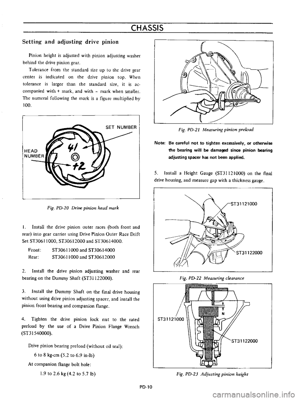
Pinion
height
is
adjusted
with
pinion
adjusting
washer
behind
the
drive
pinion
gear
Tolerance
from
the
standard
size
up
to
the
drive
gear
center
is
indicated
on
the
drive
pinion
top
When
tolerance
is
larger
than
the
standard
size
it
is
ac
companied
with
mark
and
with
mark
when
smaller
The
numeral
following
the
mark
is
a
figure
multiplied
by
100
HEAD
NUMBER
FiR
PD
20
Drive
pinion
head
mark
Install
the
drive
pinion
outer
races
both
front
and
rear
into
gear
carrier
using
Drive
Pinion
Outer
Race
Drift
Set
STJ061
1000
STJ0612000
and
Sn0614000
Froot
STJ061
1000
and
STJ0614000
Rear
STJ061
1000
and
STJ0612000
2
Install
the
drive
pinion
adjusting
washer
and
rear
bearing
on
the
Dummy
Shaft
STJI122000
3
Install
the
Dummy
Shaft
on
the
fmal
drive
housing
without
using
drive
pinion
adjusting
spacer
and
install
the
pinion
front
bearing
and
companion
flange
4
Tighten
the
drive
pinion
lock
nut
to
the
rated
preload
by
the
use
of
a
Drive
Pinion
Flange
Wrench
SnI540000
Drive
pinion
bearing
preload
without
oil
seal
6
to
8
kg
cm
5
2
to
6
9
in
lb
At
companion
flange
bolt
hole
19
to
2
6
kg
4
2
to
5
7lb
PD
l0
Fig
PD
21
Measuring
pinion
preload
Note
Be
careful
not
to
tighten
excessively
or
otherwise
the
bearing
will
be
damaged
since
pinion
bearing
adjusting
spacer
has
not
been
applied
5
Install
a
Height
Gauge
STJI12l000
on
the
flnal
drive
housing
and
measure
gap
with
a
thickness
gauge
ST31122000
Fig
PD
22
Measuring
clearance
r
ST31121000
ST31122000
Fig
PD
23
Adjusting
pinion
height
Page 89 of 513
FRONT
AXLE
FRONT
SUSPENSION
FRONT
AXLE
AND
SUSPENSION
ASSEMBLY
Removal
1
Jack
up
the
vehicle
and
support
the
vehicle
with
stands
See
the
Section
GL
2
Remove
the
hub
nuts
and
remOve
the
wheel
3
Remove
the
splash
board
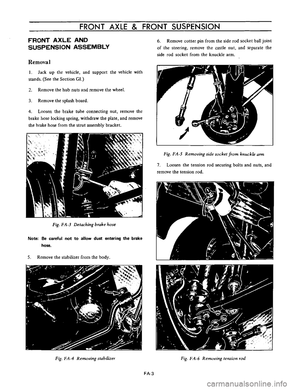
4
Loosen
the
brake
tube
connecting
nut
remove
the
brake
hose
locking
spring
withdraw
the
plate
and
remOve
the
brake
hose
from
the
strul
assembly
bracket
Fig
FA
3
Detaching
brake
hose
Note
Be
careful
not
to
allow
dust
entering
the
brake
hose
5
Remove
the
stabilizer
from
the
body
Fig
FA
4
Removing
stabilizer
6
Remove
cotter
pin
from
the
side
rod
socket
ball
joint
of
the
steering
remove
the
castle
nut
and
separate
the
side
rod
socket
from
the
knuckle
arm
Fig
F
A
5
Removing
side
socket
from
knuckle
arm
7
Loosen
the
tension
rod
securing
bolts
and
nuts
and
remove
the
tension
rod
Fig
F
A
6
RemotJing
tension
rod
FA
3
Page 90 of 513
CHASSIS
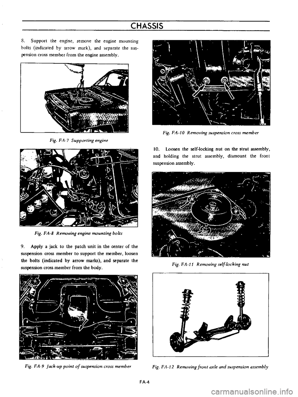
8
Support
the
engine
remove
the
engine
mounting
bolts
indicated
by
arrow
mark
and
separate
the
sus
pension
cross
member
from
the
engine
assembly
Ij
i
1
C
w
ii
lJ
c
l
I
N
r
1
a
n
h
JI
Fig
FA
7
Supporting
engine
I
IV
U
II
G
11J
r
j
F
l
I
IV
I
iL
I
0
I
l
tt
I
i
L
I
It
v
i
1
0
b
c
Ii
irti
J
I
I
1
1
Zi
J
l
ll
c
h
f
J
f
C
Fig
FA
8
Removing
engine
mounting
bolts
9
Apply
a
jack
to
the
patch
unit
in
the
center
of
the
suspension
cross
member
to
support
the
member
loosen
the
bolts
indicated
by
arrow
marks
and
separate
the
suspension
cross
member
from
the
body
Fig
FA
9
Jack
up
point
of
suspension
cross
member
Fig
FA
10
Removing
suspension
cross
member
10
Loosen
the
self
locking
nut
on
the
strut
assembly
and
holding
the
strut
assembly
dismount
the
front
suspension
assembly
Fig
F
1
11
Removing
s
flocking
nut
Fig
F
A
12
Removing
front
axle
and
suspension
assembly
FAA
Page 92 of 513

CHASSIS
Tightening
torque
of
front
suspension
cross
member
and
body
is
3
2
to
4
0
kg
m
23
1
to
28
9
ft
Ib
5
Tightening
torque
of
bolt
used
to
secure
the
upper
portion
of
the
strut
assembly
on
the
body
is
1
6
to
2
1
kg
m
11
6
to
15
2ft
lb
FRONT
AXLE
Removal
I
Jack
up
the
vehicle
remove
the
wheel
and
discon
nect
the
brake
hose
at
the
strut
outer
casing
bracket
unit
For
details
see
Removal
of
front
axle
and
suspension
assembly
2
Remove
the
brake
caliper
installation
bolts
and
remove
the
caliper
assembly
Disc
type
brake
3
Remove
the
brake
druOL
Drum
type
brake
4
Remove
the
hub
cap
with
a
flal
headed
screwdriver
or
other
proper
tool
and
hammer
Be
sure
to
tap
lightly
5
Remove
cotter
pin
from
the
wheel
bearing
lock
nut
and
remove
the
lock
nut
6
With
the
wheel
bearing
washer
and
wheel
bearing
installed
on
the
wheel
hub
remove
the
wheel
hub
from
the
spindle
In
the
case
of
a
disc
type
brake
the
wheel
hub
may
be
removed
with
the
disc
rotor
installed
on
the
wheel
hub
Fig
FA
17
Removing
wheel
hub
7
Remove
the
return
spring
and
brake
shoes
remove
brake
disc
assembly
installation
bolts
and
remove
the
brake
disc
assembly
from
the
spindle
Drum
type
brake
Fig
FA
IS
Removing
brake
disc
a
ssembly
8
Remove
baffle
plate
set
screws
and
remove
the
baffle
plate
Disc
type
brake
Fig
FA
19
Removingbaffleplate
9
Utilizing
two
grooves
inside
the
wheel
hub
tap
and
remove
the
wheel
bearing
outer
race
from
the
hub
Fig
FA
20
Removing
wheel
bearing
outer
race
FA
6
Page 96 of 513
CHASSIS
Reinstallation
Reinstall
the
wheel
bearing
in
reverse
sequence
of
removal
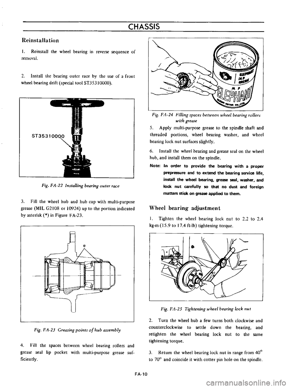
2
Install
the
bearing
outer
race
by
the
use
of
a
froot
wheel
bearing
drift
special
tool
ST353
10000
Fig
FA
22
Installing
bearing
outer
race
3
Fill
the
wheel
hub
and
hub
cap
with
multi
purpose
grease
MIL
G2108
or
10924
up
to
the
portion
indicated
by
asterisk
in
Figure
F
A
23
l
I
L
I
I
P
p
r
Fig
FA
23
Greasing
points
of
hub
assembly
4
Fill
the
spaces
between
wheel
bearing
rollers
and
grease
seal
lip
pocket
with
multi
purpose
grease
suf
ficiently
FA
10
Fig
FA
24
Filling
spaces
betweetJ
wheel
bearing
rollers
with
grease
5
Apply
multi
purpose
grease
to
the
spindle
shaft
and
threaded
portions
wheel
bearing
washer
and
wheel
bearing
lock
nut
surfaces
slightly
6
Install
the
wheei
bearing
and
grease
seal
on
the
wheel
hub
and
install
them
on
the
spindle
Note
In
order
to
provide
the
bearing
with
a
proper
prepressure
and
to
extend
the
bearing
service
life
install
the
wheel
bearing
grease
seal
washer
and
lock
nut
carefully
so
that
no
dust
and
foreign
matters
stick
on
grease
applied
to
them
Wheel
bearing
adjustment
I
Tighten
the
wheel
bearing
lock
nut
to
2
2
to
2
4
kg
m
15
9
to
174
ft
lb
tightening
torque
Fig
FA
25
Tightening
wheel
bearing
lock
nut
2
Turn
the
wheel
hub
a
few
turns
both
clockwise
and
counterclockwise
to
settle
down
the
bearing
and
retighten
the
wheel
bearing
lock
nut
to
the
same
tightening
torque
3
Return
the
wheel
bearing
lock
nut
in
range
from
400
to
700
and
coincide
it
with
cotter
pin
hole
on
the
spindle
Page 97 of 513
FRONT
AXLE
FRONT
SUSPENSION
t
t
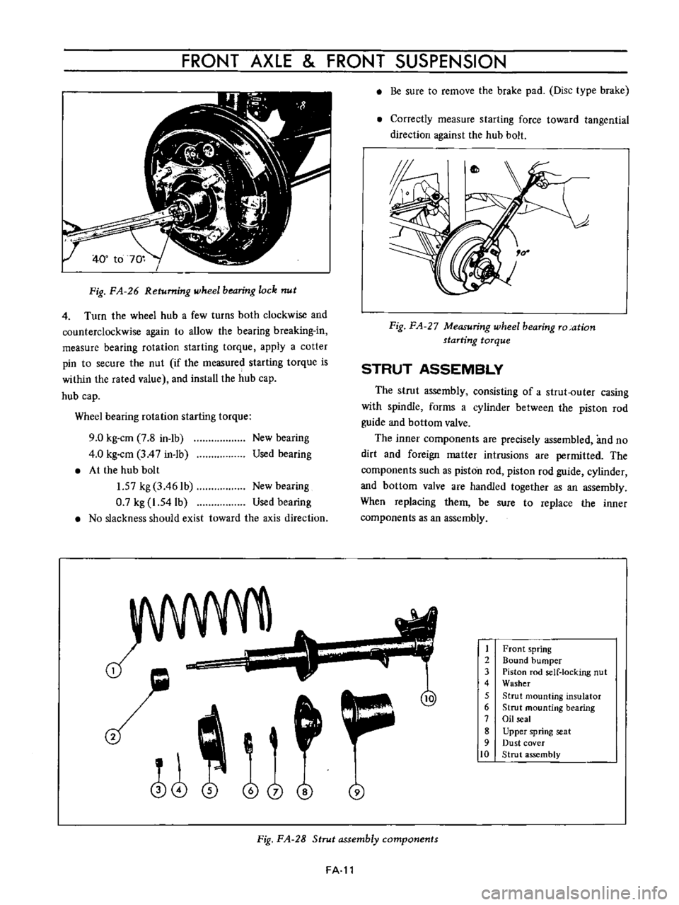
Fig
FA
26
Returning
wheel
bearing
lock
nut
4
Turn
the
wheel
hub
a
few
turns
both
clockwise
and
counterclockwise
again
to
allow
the
bearing
breaking
in
measure
bearing
rotation
starting
torque
apply
a
cotter
pin
to
secure
the
nut
if
the
measured
starting
torque
is
within
the
rated
value
and
install
the
hub
cap
hub
cap
Wheel
bearing
rotation
starting
torque
9
0
kg
cm
7
8
in
1b
4
0
kg
cm
3
4
7
in
1b
At
the
hub
bolt
1
57
kg
3
461b
New
bearing
0
7
kg
1
54lb
Used
bearing
No
slackness
should
exist
toward
the
axis
direction
New
bearing
Used
bearing
J
o
i
@
j
Be
sure
to
remove
the
brake
pad
Disc
type
brake
Correctly
measure
starting
force
toward
tangential
direction
against
the
hub
bolt
Fig
FA
27
Measuring
wheel
bearing
ro
ation
starting
torque
STRUT
ASSEMBLY
The
strut
assembly
consisting
of
a
strut
outer
casing
with
spindle
forms
a
cylinder
between
the
piston
rod
guide
and
bottom
valve
The
inner
components
are
precisely
assembled
and
no
dirt
and
foreign
matter
intrusions
are
permitted
The
components
such
as
piston
rod
piston
rod
guide
cylinder
and
bottom
valve
are
handled
together
as
an
assembly
When
replacing
them
be
sure
to
replace
the
inner
components
as
an
assembly
1
2
3
4
5
6
7
8
9
10
Front
spring
Bound
bumper
Piston
rod
self
locking
nut
Washer
Strut
mounting
insulator
Strut
mounting
bearing
Oil
seal
Upper
spring
seat
Dust
cover
Strut
assembly
Fig
FA
28
Strut
assembly
components
FA
l1