1973 DATSUN B110 lock
[x] Cancel search: lockPage 45 of 513
Adjustment
of
front
end
play
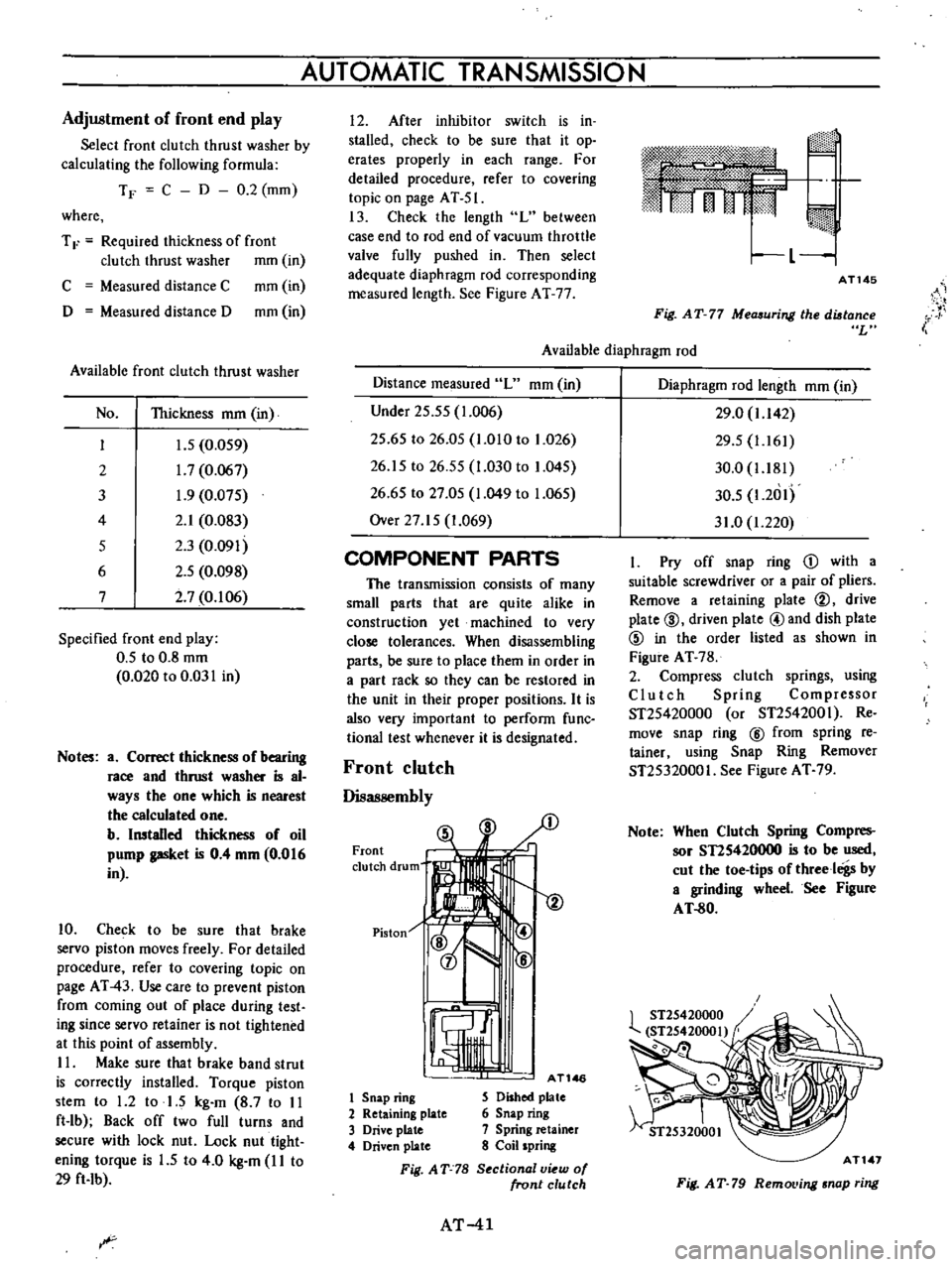
Select
front
clutch
thrust
washer
by
calculating
the
following
formula
TF
C
D
0
2
mm
where
T
F
Required
thickness
of
front
clutch
thrust
washer
mm
in
C
Measured
distance
C
mm
in
D
Measured
distance
D
mm
in
Available
front
clutch
thrust
washer
No
Thickness
mm
in
I
J
5
0
059
2
1
7
0
067
3
1
9
0
075
4
2
1
0
083
5
2
3
0
091
6
2
5
0
098
7
2
7
0
106
Specified
front
end
play
0
5
to
0
8
mm
0
020
to
0
031
in
Notes
a
Correct
thickness
of
bearing
race
and
thrust
washer
is
al
ways
the
one
which
is
nearest
the
calculated
one
b
Installed
thickness
of
oil
pump
gasket
is
0
4
mm
0
016
in
10
Check
to
be
sure
that
brake
servo
piston
moves
freely
For
detailed
procedure
refer
to
covering
topic
on
page
AT
43
Use
care
to
prevent
piston
from
coming
out
of
place
during
test
ing
since
servo
retainer
is
not
tightened
at
this
point
of
assembly
II
Make
sure
that
brake
band
strut
is
correctly
installed
Torque
piston
stem
to
1
2
to
1
5
kg
m
8
7
to
II
ft
lb
Back
off
two
full
turns
and
secure
with
lock
nut
Lock
nut
tight
ening
torque
is
1
5
to
4
0
kg
m
I
I
to
29
ft
Ib
AUTOMATIC
TRANSMISSION
I
2
After
inhibitor
switch
is
in
stalled
check
to
be
sure
that
it
op
erates
properly
in
each
range
For
detailed
procedure
refer
to
covering
topic
on
page
AT
51
13
Check
the
length
L
between
case
end
to
rod
end
of
vacuum
throttle
valve
fully
pushed
in
Then
select
adequate
diaphragm
rod
corresponding
measured
length
See
Figure
AT
77
m
rj
I
L
1
AT145
i
Fig
AT
77
Measuring
the
distance
L
Available
diaphragm
rod
Distance
measured
L
mm
in
Under
25
55
1
006
25
65
to
26
05
1
010
to
1
026
26
15
to
26
55
1
030
to
1
045
26
65
to
27
05
1
049
to
1
065
Over
27
15
1
069
COMPONENT
PARTS
The
transmission
consists
of
many
small
parts
that
are
quite
alike
in
construction
yet
machined
to
very
close
tolerances
When
disassembling
parts
be
sure
to
place
them
in
order
in
a
part
rack
so
they
can
be
restored
in
the
unit
in
their
proper
positions
It
is
also
very
important
to
perform
func
tional
test
whenever
it
is
designated
Front
clutch
Disassembly
Front
clutch
drum
Piston
1
AT146
1
Snap
ring
S
Dished
plate
2
Retaining
plate
6
Snap
ring
3
Drive
plate
7
Spring
retainer
4
Driven
plate
8
Coil
spring
Fig
AT
78
S
ctional
v
w
of
front
clutch
AT
41
Diaphragm
rod
length
mm
in
29
0
1
142
29
5
1
161
30
0
1
181
30
5
1
2
1I
31
0
1
220
I
Pry
off
snap
ring
D
with
a
suitable
screwdriver
or
a
pair
of
pliers
Remove
a
retaining
plate
@
drive
plate
@
driven
plate
@and
dish
plate
@
in
the
order
listed
as
shown
in
Figure
AT
78
2
Compress
clutch
springs
using
Clutch
Spring
Compressor
ST25420000
or
ST2542001
Re
move
snap
ring
@
from
spring
re
tainer
using
Snap
Ring
Remover
ST25320001
See
Figure
AT
79
Note
When
Clutch
Spring
Compres
sor
STIS420000
is
to
be
used
cut
the
toe
tips
of
threeloigs
by
a
grinding
wheel
See
Figure
AT
80
AT
1
Fig
AT
79
RemoL
ing
snap
ring
Page 50 of 513

I
Fig
AT
102
Removing
5
parote
plate
3
Pull
out
manual
valve
as
shown
in
Figure
AT
103
4
Remove
side
plate
Take
out
1st
2nd
shift
valve
2nd
3rd
shift
valve
pressure
modifier
valve
and
three
valve
springs
See
Figure
AT
I04
CHASSIS
AT170
Fig
AT
103
Removing
manual
valve
Note
Do
not
work
it
off
with
screw
drivers
to
avoid
damaging
machine
screws
5
Remove
side
plate
pull
out
pres
sure
regulator
valve
second
lock
valve
pressure
regulator
plug
and
two
valve
springs
sp
m
Pressure
regutlltor
sleeve
C
Prt
ssure
P
elato
piug
IZt
1
2iid3
d
h
1
alve
7
I
Solenoid
down
skutt
Throttle
back
up
alw
p
u
modif
Second
lock
alve
MllllU81
1st
2nd
shift
2nd
3rd
shift
Inspection
I
Check
valves
for
sign
of
burning
and
if
necessary
replace
2
Check
to
be
certain
that
oil
strainer
is
in
good
condition
If
found
damaged
in
any
ffi3nner
discard
3
Test
valve
springs
for
weakened
egulator
alve
3
1
ott
jj
r
of
U
d
4
t
i
i
J
j
r
r
lC
i
i
4
i
I
5
j
AT171
Fig
A
T
l
04
Removing
8ide
plate
6
Remove
side
plate
With
side
plate
removed
solenoid
downshift
valve
throttle
back
up
valve
vacuum
throttle
valve
2nd
3rd
timing
valve
and
three
valve
springs
are
free
for
removal
2nd
3rd
timing
3
ve
i
Vacuum
Ihrotlle
alve
aive
Fig
AT
L05
Components
parts
of
control
value
tension
if
necessary
replace
4
Examine
if
there
is
any
sign
of
damage
or
score
marks
on
separate
plate
If
left
unheeded
oil
will
bypass
correct
oil
passages
causing
many
types
of
abnormalities
in
the
system
AT
46
5
Check
oil
passages
in
valve
body
for
sign
of
damage
and
other
condi
tions
which
might
interfere
with
prop
er
valve
operation
6
Check
bolts
for
stripped
threads
Replace
as
required
Page 51 of 513
AUTOMATIC
TRANSMISSIO
N
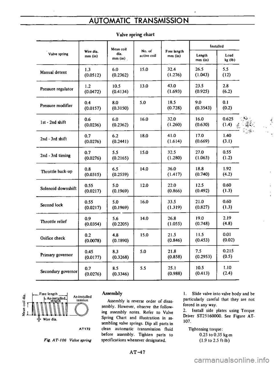
Valve
pring
chart
Installed
Wiredia
Mean
coil
No
of
Free
length
Valve
spring
mm
in
dia
active
coil
mm
in
Length
Load
mm
in
mm
in
kg
Ib
1
3
6
0
15
0
32
4
26
5
5
5
Manual
detent
0
0512
0
2362
1
276
1
043
12
1
2
10
5
13
0
43
0
23
5
2
8
Pressure
regulator
0
0472
0
4134
1
693
0
925
6
2
0
4
8
0
5
0
18
5
9
0
0
1
Pressure
modifier
0
0157
0
3150
0
728
0
3543
0
2
0
6
6
0
16
0
32
0
16
0
0
625
it
J
1st
2nd
shift
0
0236
0
2362
1
260
0
630
14
i
o
0
7
6
2
18
0
41
0
17
0
140
2nd
3
rd
shift
0
0276
0
2441
1
614
0
669
3
1
0
7
5
5
15
0
32
5
27
0
0
55
2nd
3rd
timing
0
0276
0
2165
1
280
1
063
1
2
Throttle
back
up
0
8
6
5
14
0
36
0
18
8
1
92
0
0315
0
2559
1417
0
740
4
2
0
55
5
0
12
0
22
0
12
5
0
60
Solenoid
downshift
0
0217
0
1969
0
866
0
492
1
3
0
55
5
0
16
0
33
5
21
0
0
60
Second
lock
0
0217
0
1969
1
319
0
827
1
3
0
9
5
6
14
0
26
8
19
0
2
19
Throttle
relief
0
0354
0
2205
1
055
0
748
4
8
0
2
4
8
15
0
21
5
11
5
0
01
Orifice
check
0
0078
0
1890
0
846
0
453
0
02
0
45
8
3
5
0
21
8
7
5
0
215
Primary
governor
0
0177
0
3268
0
858
0
2953
0
5
0
7
8
5
5
5
25
1
10
5
1
10
Secondary
governor
0
0276
0
3346
0
988
0
413
2
4
Free
length
L
U
d
As
ins
alled
I
t
LldnstjH
e
t
n
Ion
J
I
I
Assembly
Assembly
is
reverse
order
of
disas
sembly
However
observe
the
follow
ing
assembly
notes
Refer
to
Valve
Spring
Chart
and
illustration
in
as
sembling
valve
springs
Dip
all
parts
in
clean
automatic
transmission
fluid
before
assembly
Tighten
parts
to
specifications
whenever
designated
AT172
Fig
AT
106
Value
pring
AT
47
I
Slide
valve
into
valve
body
and
be
particularly
careful
that
they
are
not
forced
in
any
way
2
Install
side
plates
using
Torque
Driver
ST25I60000
See
Figure
AT
107
Tightening
torque
0
25
to
0
35
kg
m
1
9
to
2
5
ft
Ib
Page 63 of 513
Order
Others
AUTOMATIC
TRANSMISSION
Test
item
4
Shift
down
Dr4D2
DI
5
Shift
down
DJ
I2
l
6
Shift
down
DJ
2
7
Shift
up
I
12
8
Shift
up
or
down
when
start
ing
in
2
range
9
Parking
Abnormal
shock
oil
leakage
Procedure
Check
vehicle
speeds
and
engine
rpm
in
shifting
down
3rd
2nd
I
st
continued
while
coasting
with
acceleraling
pedal
released
in
0
range
and
engine
vacuum
pressure
of
about
450
mmHg
Check
for
shifting
down
DJ
12
and
engine
braking
and
further
for
shifting
down
12
11
and
engine
braking
after
shifting
the
lever
into
I
range
with
the
accelerator
pedal
released
and
the
engine
vacuum
pressure
of
0
mmHg
while
driving
at
about
SO
km
h
31
MPH
in
DJ
range
Check
for
quick
shifting
down
DJ
2
and
engine
braking
after
shifting
the
lever
into
2
range
while
driving
at
about
50
km
h
31
MPH
in
DJ
range
Further
check
the
transmission
for
being
locked
to
the
2nd
gear
ratio
regardless
of
vehicle
speed
Check
for
the
transmission
not
shifting
up
during
acceIera
tion
when
starting
in
1
t
nge
It
Check
the
transmission
for
not
shifting
up
or
down
durih
t
acceleration
or
deceleration
when
starting
in
2
range
Confirm
that
vehicle
will
not
move
on
grade
when
shifting
to
P
range
Put
on
record
of
observed
conditions
during
these
tests
such
as
gear
noise
abnormal
noise
of
clutches
and
acceleration
performance
AT
59
Page 64 of 513

CHASSIS
SERVICE
DATA
AND
SPECIFICATIONS
General
specifications
Torque
converter
Type
Stall
torque
ratio
Transmission
Type
Control
elements
Gear
ratio
Selector
positions
Oil
pump
Type
Number
of
pump
Oil
Capacity
Hydraulic
control
system
Lubrication
system
Cooling
system
Multiple
disc
clutch
Band
brake
Multiple
disc
brake
One
way
clutch
1st
lnd
3rd
Reverse
P
Park
R
Reverse
N
Neutral
D
Drive
1
lnd
lock
I
Lock
up
AT
60
Symmetrical3
element
I
stage
l
phase
torque
converter
coupling
2
0
I
3
speed
forward
and
one
speed
reverse
with
planetary
gear
train
1
I
I
I
2
458
1
458
1
000
2
182
The
transmission
is
placed
in
neutral
The
output
shaft
is
fixed
The
engine
can
be
started
Backward
running
The
transmission
is
in
neutral
The
engine
can
be
started
Up
or
downshifts
automatically
to
and
from
1st
lnd
and
top
Fixed
at
2nd
Fixed
at
low
or
downshifts
from
2nd
Internally
intermeslting
involute
gear
pump
Automatic
transmission
fluid
Dexron
type
5
5
liters
57
8
U
S
qts
47
8
Imp
qts
Approximately
1
7
liters
27
8
U
S
qts
2
3
8
Imp
qts
in
torque
converter
Controlled
by
detecting
the
negative
pressure
of
intake
manifold
and
the
revolution
speed
of
output
shaft
Forced
lubrication
by
an
oil
pwnp
Air
cooled
Page 66 of 513
CHASSIS
Engine
idling
and
stall
revolution
Engine
with
emission
control
device
Idling
revolution
rpm
650
at
0
position
800
at
N
position
1
750
to
2
000
Stall
revolution
rpm
Tightening
torque
kg
m
ft
Ib
Test
plug
oil
pressure
inspection
hole
Support
actuator
parking
rod
inserting
position
to
rear
extension
Oil
charging
pipe
to
case
Dust
cover
to
converter
housing
Selector
range
lever
to
manual
shaft
Lower
shift
rod
lock
nut
6
5
t07
5
47
to
54
0
8
to
1
0
5
8
to
7
2
4
0
to
5
0
30
to
36
4
0
to
5
0
30
to
36
2
0
to
2
5
15
to
18
0
5
to
0
7
3
6
to
5
1
0
5
to
0
7
3
6toS
I
1
2
to
1
5
8
7
to
10
8
1
5
to
4
0
II
to
29
1
3
to
1
8
9
4
to
13
0
55
to
0
75
4
0
to
5
4
0
25
to
0
35
1
9
to
2
5
0
25
to
0
35
1
9
to
2
5
0
5
to
0
7
3
6
to
5
I
0
25
to
0
35
1
9
to
2
5
0
5
to
0
7
3
6
to
5
1
0
6
to
0
8
4
4
to
5
8
0
5
to
0
7
3
6
to
5
1
3
0
to
4
0
22
to
29
3
0
to
5
0
22
to
36
14
to
2
1
10
to
15
0
8
to
l
l
5
8
to
7
9
0
55
to
0
75
4
0
to
5
4
0
55
to
0
75
4
0
to
5
4
3
0
to
4
0
22
to
29
2
0
to
2
9
15
to
21
Drive
plate
to
crankshaft
Drive
plate
to
torque
converter
Converter
housing
to
engine
Transmission
case
to
converter
housing
Transmission
case
to
rear
extension
Oil
pan
to
transmission
case
Servo
piston
retainer
to
transmission
case
Piston
stem
when
adjuting
band
brake
Piston
stem
lock
nut
One
way
clutch
inner
race
to
transmission
case
Control
valve
body
to
transmission
case
Lower
valve
body
to
upper
valve
body
Side
plate
to
control
valve
body
Nut
for
control
valve
reamer
bolt
Oil
strainer
to
lower
valve
body
Governor
valve
body
to
oil
distributor
Oil
pump
housing
to
oil
pump
cover
Inhibitor
switch
to
transmh
sion
case
Manual
shaft
lock
nut
Oil
tube
to
transmission
case
Turn
back
two
turns
after
tightening
AT
62
Page 68 of 513
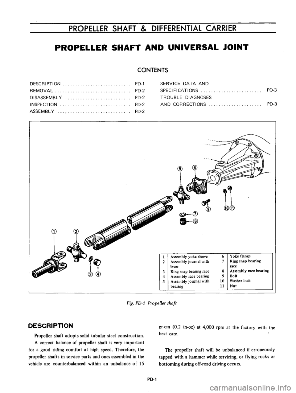
PROPELLER
SHAFT
DIFFERENTIAL
CARRIER
PROPELLER
SHAFT
AND
UNIVERSAL
JOINT
CONTENTS
DESC
R
I
PTI
ON
REMOVAL
DISASSEMBL
Y
INSPECTION
ASSEMBL
Y
PD
PD
2
PD
2
PD
2
PD
2
SERVICE
DATA
AND
SPECIFICATIONS
TROUBLE
DIAGNOSES
AND
CORRECTIONS
PD
3
PD
3
j
j
lI
ID
1
Assembly
yoke
sleeve
2
As
mbly
journal
with
lever
3
Ring
snap
bearing
race
4
Assembly
race
bearing
5
Assembly
journal
with
bearing
6
Yoke
flange
7
Ring
snap
bearing
race
8
Assembly
race
bearing
9
Bolt
10
Washer
lock
11
Nut
Fig
PD
l
Propeller
shaft
DESCRIPTION
Propeller
shaft
adopts
solid
tubular
steel
construction
A
correct
balance
of
propeller
shaft
is
very
important
for
a
good
riding
comfort
at
high
speed
Therefore
the
propeller
shafts
in
service
parts
and
ones
assembled
in
the
vehicle
are
counterbalanced
within
an
unbalance
of
IS
gr
cm
0
2
in
oz
at
4
000
rpm
at
the
factory
with
the
best
care
The
propeller
shaft
will
be
unbalanced
if
erroneously
tapped
with
a
hammer
while
servicing
or
flying
rocks
or
bottoming
during
off
road
driving
occurs
PD
1
Page 73 of 513
CHASSIS
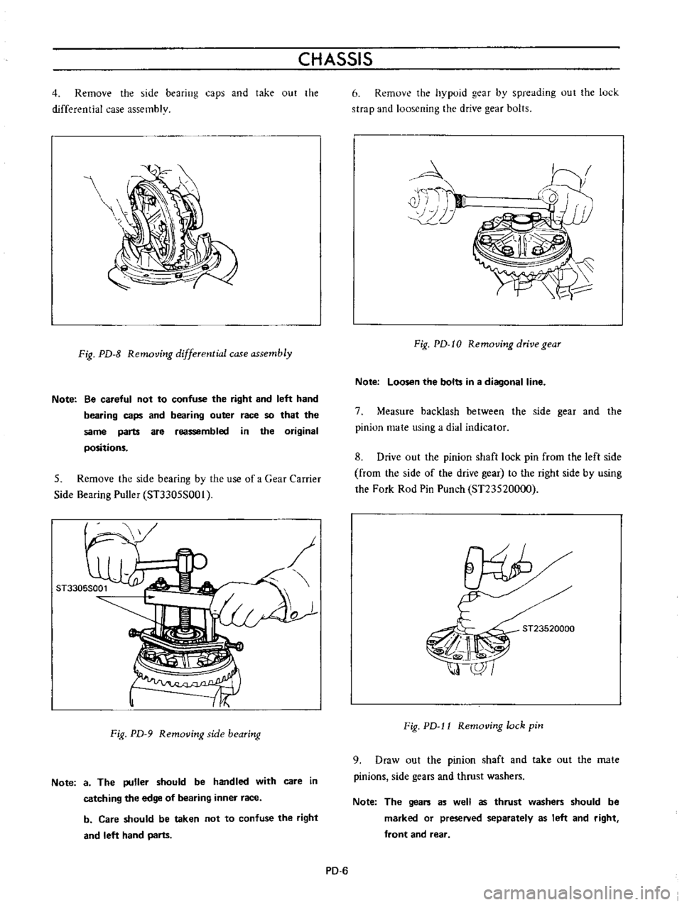
4
Remove
the
side
bearing
caps
and
take
out
the
differential
case
assembly
Fig
PD
8
Removing
differential
case
assembly
Note
Be
careful
not
to
confuse
the
right
and
left
hand
bearing
caps
and
bearing
outer
race
so
that
the
same
parts
are
reassembled
in
the
original
positions
5
Remove
the
side
bearing
by
the
use
of
a
Gear
Carrier
Side
Bearing
Puller
ST3305S001
o
Fig
PD
9
Removing
side
bearing
Note
a
The
puller
should
be
handled
with
care
in
catching
the
edge
of
bearing
inner
race
b
Care
should
be
taken
not
to
confuse
the
right
and
left
hand
parts
6
Remove
the
hypoid
gear
by
spreading
out
the
luck
strap
and
loosening
the
drive
gear
bolts
4
i
T
II
10
Fig
PD
I0
Removing
drive
gear
Note
Loosen
the
bolts
in
a
diagonal
line
7
Measure
backlash
between
the
side
gear
and
the
pinion
mate
using
a
dial
indicator
8
Drive
out
the
pinion
shaft
lock
pin
from
the
left
side
from
the
side
of
the
drive
gear
to
the
right
side
by
using
the
Fork
Rod
Pin
Punch
ST23520000
ST23520000
Fig
PD
l1
Removing
lock
pin
9
Draw
out
the
pinion
shaft
and
take
out
the
mate
pinions
side
gears
and
thrust
washers
Note
The
gears
as
well
as
thrust
washers
should
be
marked
or
preseNed
separately
as
left
and
right
front
and
rear
PD
6