1973 DATSUN B110 lock
[x] Cancel search: lockPage 98 of 513
fl
i
i
I
1
I
I
i
2
4
L
thi7
lrr
I
1
1
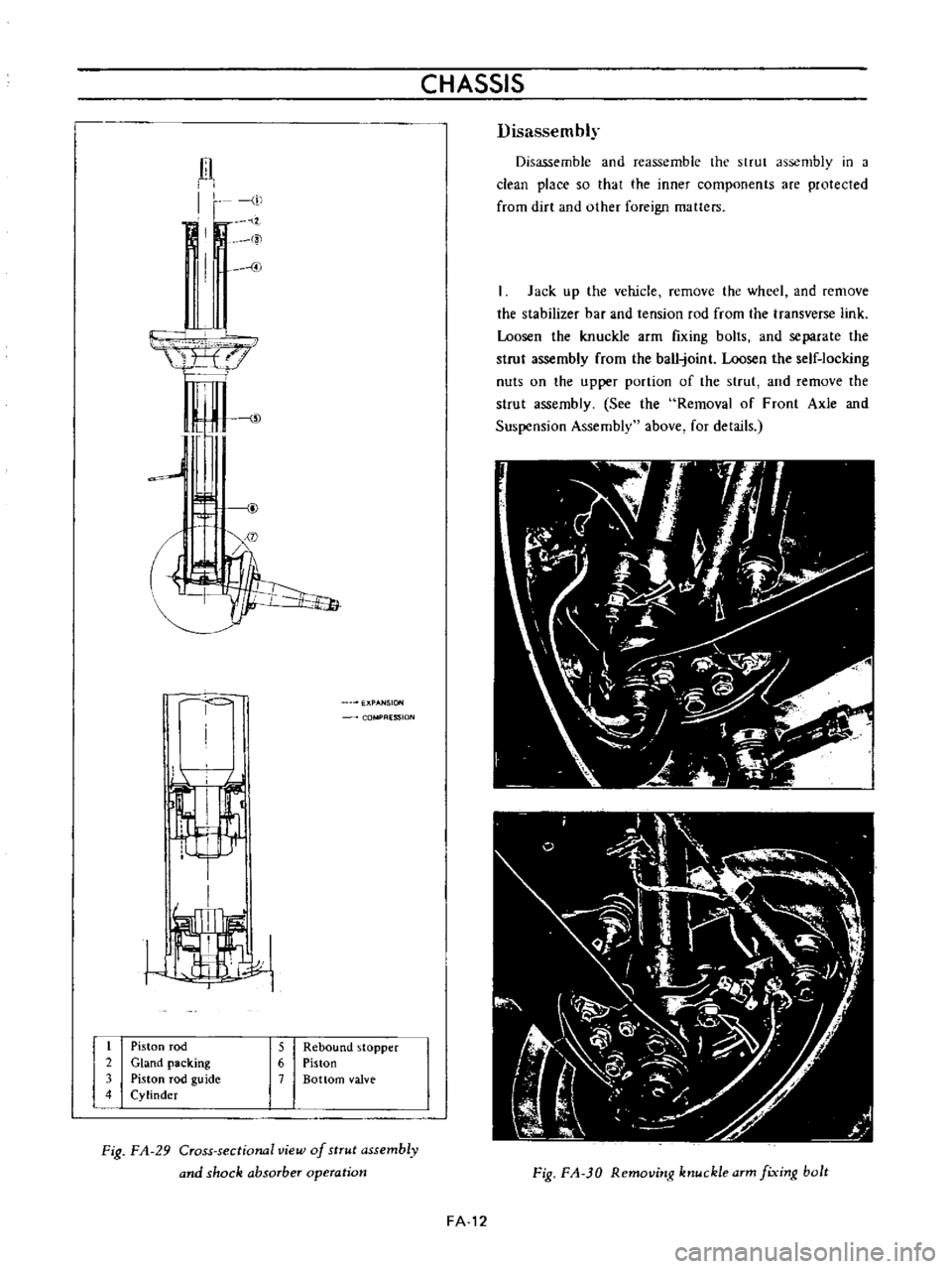
Piston
rod
2
Gland
packing
3
Piston
rod
guide
4
Cylinder
CHASSIS
ESSION
5
Rebound
stopper
6
Piston
7
Bottom
valve
Fig
FA
29
Cross
sectional
view
of
strut
assembly
and
shock
absorber
operation
Disassembly
Disassemble
and
reassemble
the
strut
assembly
in
a
clean
place
so
that
the
inner
components
are
protected
from
dirt
and
other
foreign
matters
Jack
up
the
vehicle
remove
the
wheel
and
remove
the
stabilizer
bar
and
tension
rod
from
the
transverse
link
Loosen
the
knuckle
arm
fIxing
bolts
and
separate
the
strut
assembly
from
the
ball
joint
Loosen
the
self
locking
nuts
on
the
upper
portion
of
the
strut
and
remove
the
strut
assembly
See
the
Removal
of
Front
Axle
and
Suspension
Assembly
above
for
details
Fig
FA
JO
Removitlg
ktluckle
arm
fixitlg
bolt
FA
12
Page 99 of 513
FRONT
AXLE
FRONT
SUSPENSION
Fig
FA
31
Removing
front
strut
assembly
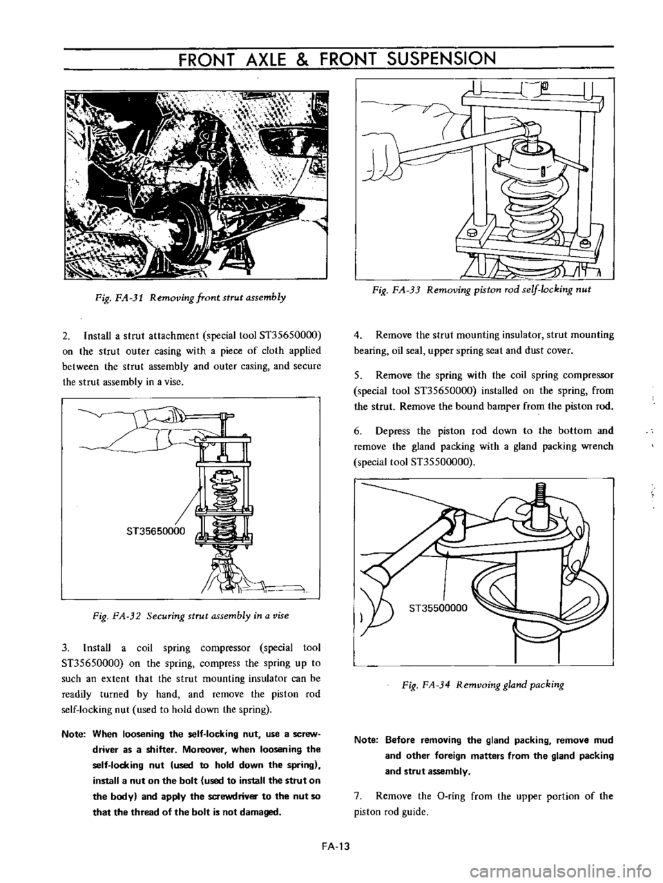
2
InstaU
a
strut
attachment
special
tool
ST35650000
00
the
strut
outer
casing
with
a
piece
of
cloth
applied
between
the
strut
assembly
and
outer
casing
and
secure
the
strut
assembly
in
a
vise
J
1
i
kj
ST35650000
W
lL
bi
Fig
FA
32
Securing
strut
assembly
in
a
vise
3
1nstaU
a
coil
spring
compressor
special
tool
ST35650000
on
the
spring
compress
the
spring
up
to
such
an
extent
that
the
strut
mounting
insulator
can
be
readily
turned
by
hand
and
remove
the
piston
rod
self
locking
nut
used
to
hold
down
the
spring
Note
When
loosening
the
self
locking
nut
use
a
screw
driver
as
a
shitter
Moreover
when
loosening
the
self
locking
nut
used
to
hold
down
the
spring
install
a
nut
on
the
bolt
used
to
install
the
strut
on
the
body
and
apply
the
saewdrivOI
to
the
nut
so
that
the
thread
of
the
bolt
is
not
damaged
r
U
jlD
L1
19
71
it
fr
Fig
FA
33
Removing
piston
rod
self
locking
nut
4
Remove
the
strut
mounting
insulator
strut
mounting
bearing
oil
seal
upper
spring
seat
and
dust
cover
5
Remove
the
spring
with
the
coil
spring
compressor
special
tool
ST35650000
installed
on
the
spring
from
the
strut
Remove
the
bound
bamrer
from
the
piston
rod
6
Depress
the
piston
rod
down
to
the
bottom
and
remove
the
gland
packing
with
a
gland
packing
wrench
special
tool
ST35500000
I
ST35500000
Fig
FA
34
Remvoing
gland
packing
Note
Before
removing
the
gland
packing
remove
mud
and
other
foreign
matters
from
the
gland
packing
and
strut
assembly
7
Remove
the
O
ring
from
the
upper
portion
of
the
piston
rod
guide
FA
13
Page 103 of 513
FRONT
AXLE
FRONT
SUSPENSION
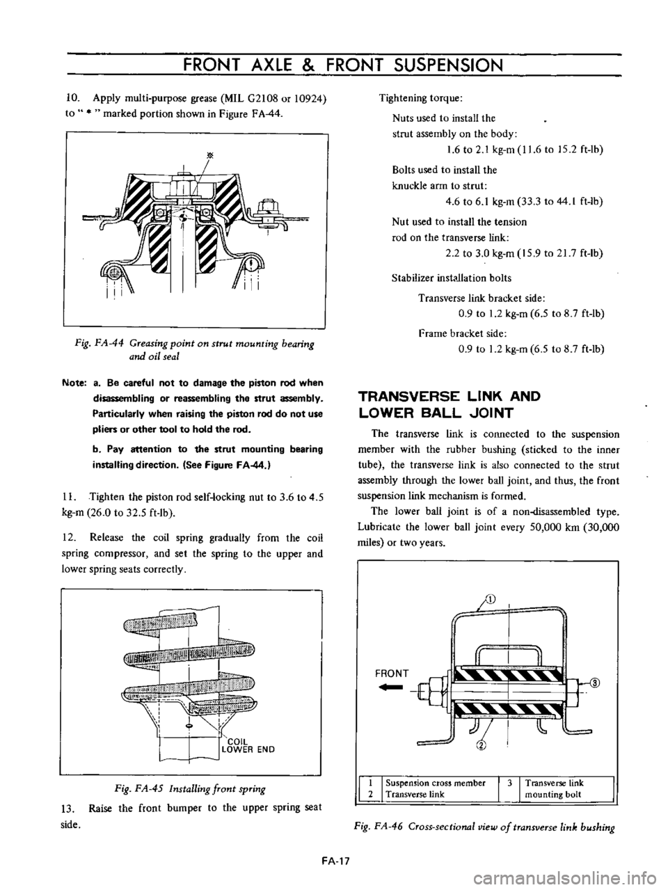
10
Apply
multi
purpose
grease
MIL
G2108
or
10924
to
marked
portion
shown
in
Figure
FA
44
Fig
FA
44
Greasing
point
on
strut
mounting
bearing
and
oil
seal
Note
a
Be
careful
not
to
damage
the
piston
rod
when
disassembling
or
reassembling
the
strut
assembly
Particularly
when
raising
the
piston
rod
do
not
use
pliers
or
other
tool
to
hold
the
rod
b
Pay
attention
to
the
strut
mounting
bearing
installing
direction
See
Figure
FA
44
1
L
Tighten
the
piston
rod
self
locking
nut
to
3
6
to
4
5
kg
m
26
0
to
32
5
ft
1b
12
Release
the
coil
spring
gradually
from
lhe
coil
spring
compressor
and
set
the
spring
to
the
upper
and
lower
spring
seats
correctly
f
I
I
COIL
l
J
LOWER
EN
D
Fig
FA
45
Installing
front
spring
13
Raise
the
front
bumper
to
the
upper
spring
seat
side
Tightening
torque
Nuts
used
to
install
the
strut
assembly
on
the
body
1
6
to
2
1
kg
m
11
6
to
15
2
ft
lb
Bolts
used
to
install
the
knuckle
arm
to
strut
4
6
to
6
1
kg
m
33
3
to
44
I
ft
lb
Nut
used
to
install
the
tension
rod
on
the
transverse
link
2
2
to
3
0
kg
m
15
9
to
21
7
ft
Ib
Stabilizer
inst
llation
bolts
Transverse
link
bracket
side
0
9
to
1
2
kg
m
6
5
to
8
7
ft
lb
Frame
bracket
side
0
9
to
1
2
kg
m
6
5
to
8
7
ft
lb
TRANSVERSE
LINK
AND
LOWER
BALL
JOINT
The
transverse
link
is
connected
to
the
suspension
member
with
the
rubher
bushing
sticked
to
the
inner
tube
the
transverse
link
is
also
connected
to
the
strut
assembly
through
the
lower
ball
joint
and
thus
the
front
suspension
link
mechanism
is
formed
The
lower
ball
joint
is
of
a
non
lisassembled
type
Lubricate
the
lower
ball
joint
every
50
000
km
30
000
miles
or
two
years
JD
y
I
II
I
II
F
T
ill
3
YJ
t
tjli
t
11
I
Suspension
cross
member
I
3
I
Transverse
link
2
Transverse
link
mounting
bolt
Fig
FA
46
Cross
sectional
view
of
transverse
link
bushing
FA
17
Page 108 of 513
CHASSIS
For
high
speed
Over
100
km
h
or
60
MPH
ADJUSTMENT
OF
WHEEL
ALIGNMENT
Use
a
turning
radius
gauge
and
alignment
gauge
for
the
measurement
2
Carry
out
wheel
alignment
on
a
flat
surface
with
tire
air
pressure
adjusted
to
the
normal
pressure
ADJUSTMENT
OF
VEHICLE
LEVEL
Vehicle
level
is
adjusted
by
changing
springs
ADJUSTMENT
OF
TOE
IN
Measure
toe
in
with
a
toe
in
gauge
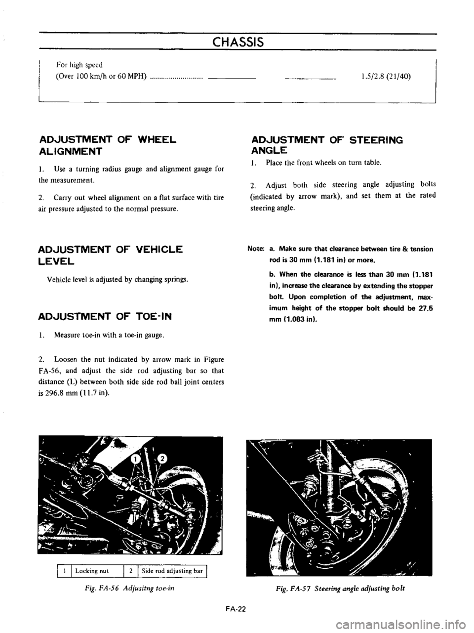
2
Loosen
the
nut
indicated
by
arrow
mark
in
Figure
FA
56
and
adjust
the
side
rod
adjusting
bar
so
that
distance
L
between
both
side
side
rod
ball
joint
centers
is
296
8
mm
11
7
in
I
1
I
Locking
nu
t
I
2
I
Side
rod
adjusting
bar
I
Fig
FA
56
Adjusitng
toe
in
1
5
2
8
21
40
ADJUSTMENT
OF
STEERING
ANGLE
1
Place
the
front
wheels
on
turn
table
2
Adjust
both
side
steering
angle
adjusting
bolts
indicated
by
arrow
mark
and
set
them
al
the
rated
steering
angle
Note
8
Make
sure
that
clearance
between
tire
tension
rod
is
30
mm
11
181
in
or
more
b
When
the
clearance
is
less
than
30
mm
1
181
in
inaease
the
clearance
by
extending
the
stopper
bolt
Upon
completion
of
the
adjustment
max
imum
height
of
the
stopper
bolt
should
be
27
5
mm
1
083
in
Fig
FA
57
Steering
angle
adjusting
bolt
FA
22
Page 110 of 513

CHASSIS
Strut
assembly
Strut
outer
diameter
Piston
rod
diameter
mmlin
nml
in
45
17
7
18
0
709
15
0
984
Piston
diameter
mmlin
Damping
force
at
piston
speed
0
3
m
sec
Expansion
kg
Ib
Compression
kg
lb
48
106
22
48
5
Piston
rod
Bend
limit
Wear
limit
mm
in
0
1
0
0039
mm
in
0
025
0
0010
Piston
cylinder
Bend
limit
Wear
limit
inside
mm
in
mm
in
0
2
0
0079
0
1
0
0039
17
0
669
Stabilizer
bar
diameter
mm
in
Front
wheel
bearing
rotation
starting
torque
kg
cm
in
lb
Ball
joint
shaking
torque
kg
cm
in
lb
Ball
joint
end
play
axial
direction
mm
in
9
0
7
8
35
to
60
30
4
to
52
1
0
3
to
1
0
0
0118
to
0
0394
TIGHTENING
TORQUE
Front
axle
Brake
disc
rotor
and
hub
assembly
tightening
torque
Wheel
bearing
lock
nut
Disc
brake
caliper
fixing
bolt
Buffle
plate
installation
screw
Brake
disc
assembly
installation
bolt
kg
m
ft
lb
4
4
to
5
9
31
8
to
42
7
2
2
to
2
4
15
9
to
174
4
6
to
6
1
33
3
to
44
1
0
3
to
0
4
2
1
to
2
9
2
7
to
3
7
19
5
to
26
8
Strut
assembly
Gland
packing
tightening
torque
Piston
rod
self
locking
nut
Upper
support
nut
8
0
to
11
0
57
8
to
79
5
3
6
to
4
5
26
0
to
32
5
1
6
to
2
1
I
1
6
to
15
2
Transverse
link
and
ball
joint
Bolts
used
to
install
the
knuckle
arm
to
strut
Ball
joint
castle
nut
Bolts
used
to
install
the
transverse
link
to
ball
4
6
to
6
1
33
3
to
44
1
5
5
to
7
4
39
8
to
53
5
FA
24
Page 117 of 513
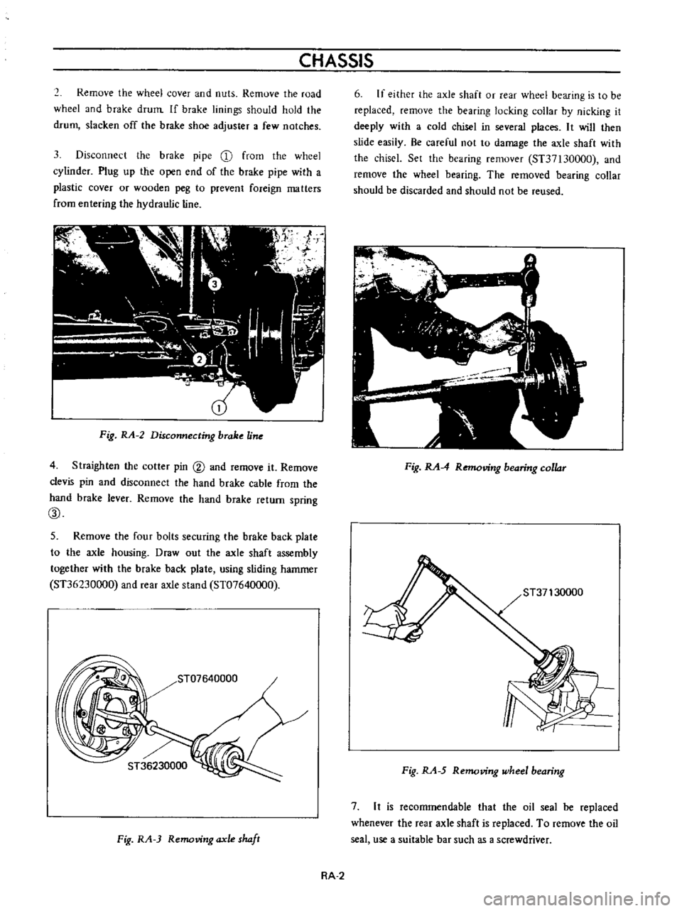
CHASSIS
2
Remove
the
wheel
cover
and
nuts
Remove
the
road
wheel
and
b
rake
drum
If
brake
linings
should
hold
the
drum
slacken
off
the
brake
shoe
adjuster
a
few
notches
3
Disconnect
the
brake
pipe
CD
from
the
wheel
cylinder
Plug
up
the
open
end
of
the
brake
pipe
with
a
plastic
cover
or
wooden
peg
to
prevent
foreign
matters
from
entering
the
hydraulic
line
Fig
RA
2
Disconnecting
brake
Une
4
Straighten
the
cotler
pin
@
and
remove
it
Remove
clevis
pin
and
disconnect
the
hand
brake
cable
from
the
hand
brake
lever
Remove
the
hand
brake
return
spring
CID
5
Remove
the
four
bolts
securing
the
brake
back
plate
to
the
axle
housing
Draw
out
the
axle
shaft
assembly
together
with
the
brake
back
plate
using
sliding
hammer
ST36230000
and
rear
axle
stand
ST07640000
ST07640000
I
Fig
RA
3
Removing
axle
shaft
6
If
either
the
axle
shaft
or
rear
wheel
bearing
is
to
be
replaced
remove
the
bearing
locking
collar
by
nicking
it
deeply
with
a
cold
chisel
in
several
places
It
will
then
slide
easily
Be
careful
not
to
damage
the
axle
shaft
with
the
chiscl
Set
the
bearing
remover
ST37130000
and
remove
the
wheel
bearing
The
removed
bearing
collar
should
be
discarded
and
should
not
be
reused
Fig
RA
4
Removing
bearing
collar
Fig
RA
5
Removing
wheel
bearing
7
It
is
recommendable
that
the
oil
seal
be
replaced
whenever
the
rear
axle
shaft
is
replaced
To
remove
the
oil
seal
use
a
suitable
bar
such
as
a
screwdriver
RA
2
Page 120 of 513
REAR
AXLE
REAR
SUSPENSION
DESCRIPTION
Rear
suspension
consists
of
semi
elliptic
leaf
springs
telescopic
hydraulic
shock
absorbers
and
rubber
bumpers
The
rear
spring
center
pin
is
off
set
110
mm
4
33
in
toward
the
front
from
the
center
of
the
spring
This
is
done
to
reduce
spring
wind
up
and
to
decrease
the
arc
while
the
rear
wheel
swings
through
Thereby
minimizing
the
possibility
of
the
rear
suspension
effecting
vehicle
stability
Iso
clamp
devices
are
used
for
attaching
the
axle
housing
to
the
spring
The
leaf
springs
shock
absorbers
and
rear
axle
housing
are
mounted
on
rubber
bushings
at
each
end
to
minimize
noise
and
vibration
of
the
transmission
to
the
car
body
and
passenger
compartment
REAR
SPRING
Removal
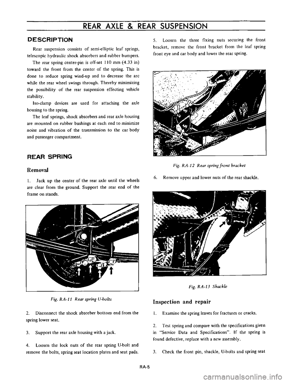
1
Jack
up
the
center
of
the
rear
axle
until
the
wheels
are
clear
from
the
ground
Support
the
rear
end
of
the
frame
on
stands
Fig
RA
l1
Rear
spring
U
bo
ts
2
Disconnect
the
shock
absorber
bottom
end
from
the
spring
lower
seat
3
Support
the
rear
axle
housing
with
a
jack
4
Loosen
the
lock
nuts
of
the
rear
spring
U
bolt
and
remove
the
bolts
spring
seat
location
plates
and
seat
pads
5
Loosen
the
three
fixing
nuts
securing
the
front
bracket
remove
the
front
bracket
from
the
leaf
spring
front
eye
and
car
body
and
lower
the
rear
spring
Fig
RA
12
Rear
spring
front
bracket
6
Remove
upper
and
lower
nuts
of
the
rear
shackle
Fig
RA
13
Shackle
Inspection
and
repair
1
Examine
the
spring
leaves
for
fractures
or
cracks
2
Test
spring
and
compare
with
the
specifications
given
in
Service
Data
and
Specifications
If
the
spring
is
found
defective
replace
with
a
new
assembly
3
Check
the
front
pin
shackle
U
bolts
and
spring
seat
RA
5
Page 134 of 513
CHASSIS
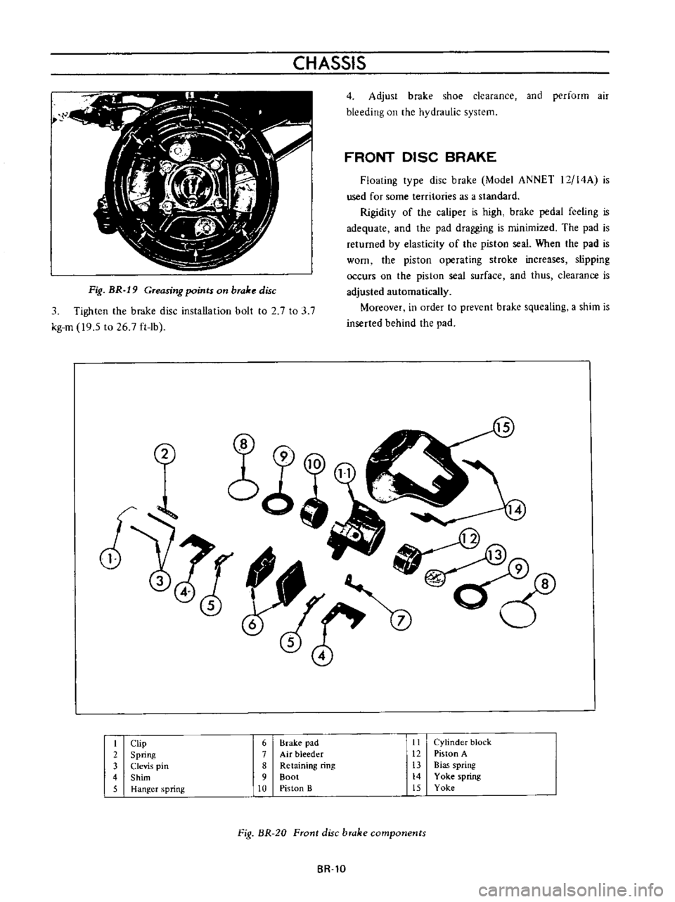
Fig
BR
19
Greasing
points
on
brake
disc
3
Tighten
the
brake
disc
installation
bolt
to
2
7
to
3
7
kg
m
19
5
to
26
7
ft
lb
4
Adjust
brake
shoe
clearance
and
perform
air
bleeding
on
the
hydraulic
system
FRONT
DISC
BRAKE
Floating
type
disc
brake
Model
ANNET
12
14A
is
used
for
some
territories
as
a
standard
Rigidity
of
the
caliper
is
high
brake
pedal
feeling
is
adequate
and
the
pad
dragging
is
minimized
The
pad
is
returned
by
elasticity
of
the
piston
seal
When
the
pad
is
worn
the
piston
operating
stroke
increases
slipping
occurs
on
the
piston
seal
surface
and
thus
clearance
is
adjusted
automatically
Moreover
in
order
to
prevent
brake
squealing
a
shim
is
inserted
behind
the
pad
2
I
Clip
6
Brake
pad
II
Cylinder
block
2
Spring
7
Air
bleeder
12
Piston
A
3
Clevis
pin
8
Retaining
ring
13
Bias
spring
4
Shim
9
Boot
14
Yoke
spring
5
Hanger
spring
10
Piston
B
15
Yoke
Fig
BR
20
Front
disc
brake
components
BR
lO