1973 DATSUN B110 lock
[x] Cancel search: lockPage 166 of 513
I
CHASSIS
4
Adjust
the
preload
of
the
worm
bearing
by
selecting
the
thickness
of
he
worm
bearing
shim
five
kinds
0
05
to
0
20
mm
0
0020
to
0
0079
in
so
that
the
initial
torque
of
the
steering
wheel
is
2
0
to
5
0
kg
cm
27
8
to
694
in
oz
without
sector
shaft
J
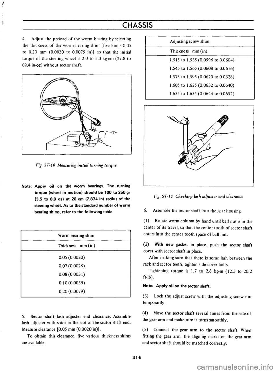
Fig
ST
10
Measuring
initial
tunring
torque
Note
Apply
oil
on
the
worm
bearings
The
turning
torque
wheel
in
motion
should
be
100
to
250
gr
13
5
to
8
8
oz
at
20
em
7
874
in
radius
of
the
steering
wheel
As
to
the
standard
number
of
worm
bearing
shims
refer
to
the
following
table
Worm
bearing
shim
Thickness
mm
in
0
05
0
0020
0
07
0
0028
0
08
0
0031
0
10
0
0039
0
20
0
0079
5
Sector
shaft
lash
adjuster
end
clearance
Assemble
lash
adjuster
with
shim
in
the
slot
of
the
sector
shaft
end
Measure
clearance
0
05
mm
0
0020
in
To
obtain
this
clearance
five
various
thickness
shims
are
available
Adjusting
screw
shim
Thickness
mm
in
1
515
to
1
535
0
0596
to
0
0604
1
545
to
1
565
0
0608
to
0
0616
1
575
to
1
595
0
0620
to
0
0628
1
605
to
1
625
0
0632
to
0
0640
1
63510
1
655
0
0644
to
0
0652
Fig
ST
J
J
Checking
lash
adjuster
end
clearance
6
Assemble
the
sector
shaft
into
the
gear
housing
I
Rotate
worm
column
by
hand
unlil
ball
nut
is
in
the
center
of
its
travel
so
that
the
center
tooth
of
sector
shaft
enters
into
the
center
tooth
space
of
ball
nut
2
With
new
gasket
in
place
push
the
sector
shaft
cover
with
sector
shaft
in
place
After
making
sure
that
there
is
some
lash
between
the
rack
and
sector
teeth
tighten
side
cover
bolts
Tightening
torque
is
I
7
to
2
8
kg
m
I2
3
to
20
2
ft
lb
Note
Apply
oil
on
the
sector
shaft
3
Lock
the
adjust
screw
with
the
adjusting
screw
nut
temporarily
4
Move
the
sector
shaft
several
times
from
the
side
of
the
gear
arm
and
make
sure
it
turns
smoothly
5
Connect
the
gear
arm
to
the
sector
shaft
When
fitting
the
gear
arm
the
aligning
marks
on
the
gear
arm
and
sector
shaft
should
be
matched
correctly
ST
6
Page 167 of 513
STEERING
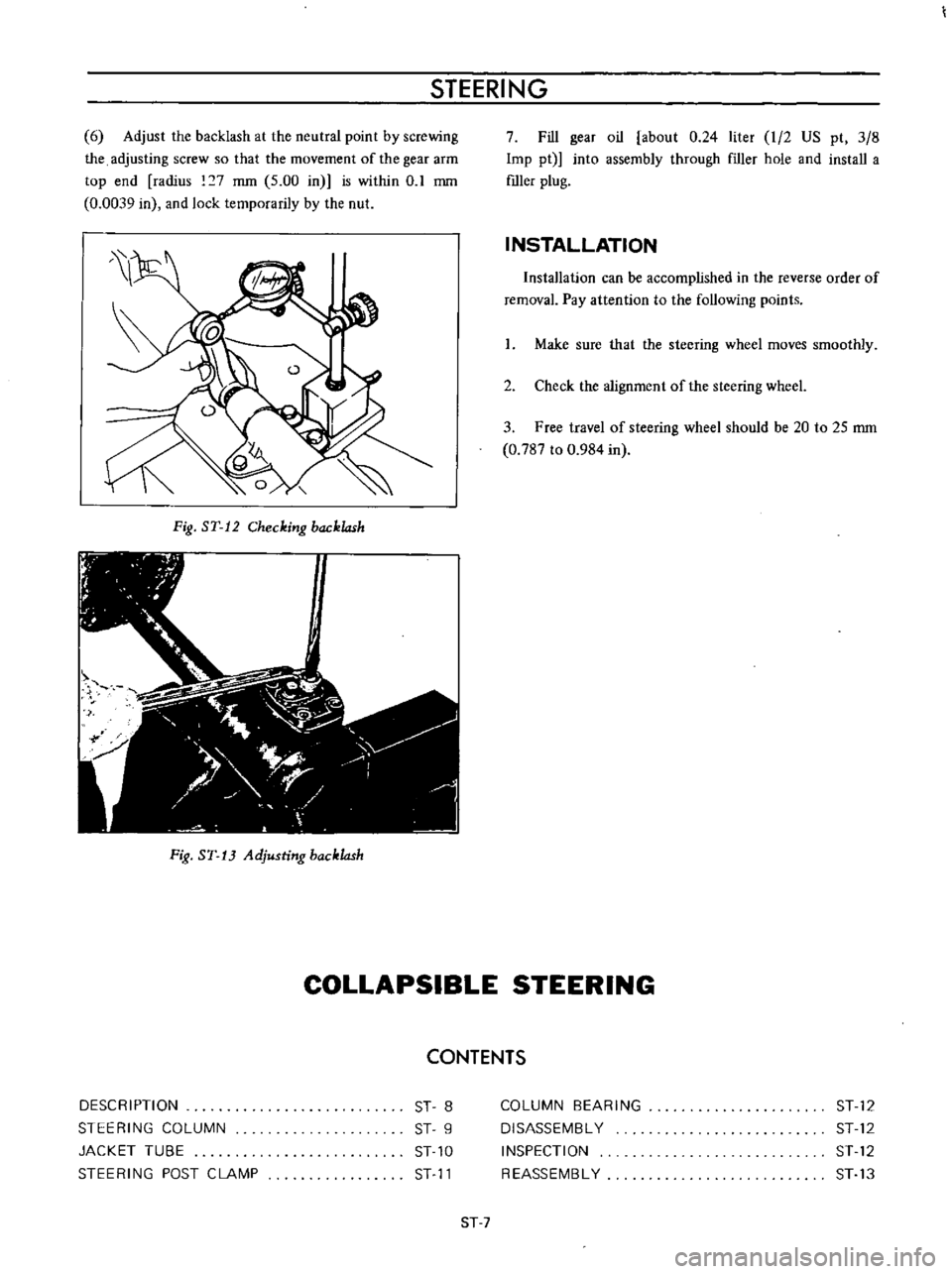
6
Adjust
the
backlash
at
the
neutral
point
by
screwing
the
adjusting
screw
so
that
the
movement
of
the
gear
arm
top
end
radius
7
mm
5
00
in
is
within
0
1
mm
0
0039
in
and
lock
temporarily
by
the
nut
Fig
ST
12
Checking
backlash
Fig
ST
13
Adjusting
backlash
7
Fill
gear
oil
about
0
24
liter
I
2
US
pt
3
8
Imp
pt
into
assembly
through
f1ller
hole
and
install
a
mIer
plug
INSTALLATION
Installation
can
be
accomplished
in
the
reverse
order
of
removal
Pay
attention
to
the
following
points
I
Make
sure
that
the
steering
wheel
moves
smoothly
2
Check
the
alignment
of
the
steering
wheeL
3
Free
travel
of
steering
wheel
should
be
20
to
25
mm
0
787
to
0
984
in
COLLAPSIBLE
STEERING
CONTENTS
DESCRIPTION
STEERING
COLUMN
JACKET
TUBE
STEERING
POST
CLAMP
ST
8
ST
9
ST
10
ST
11
COLUMN
BEARING
DISASSEMBL
Y
INSPECTION
REASSEMBL
Y
ST
12
ST
12
ST
12
ST
13
ST
7
Page 170 of 513

CHASSIS
The
construction
of
the
steering
column
is
as
such
that
the
lower
shaft
is
fitted
into
the
upper
tube
when
a
compressing
force
is
applied
to
the
lower
shaft
r
I
1
V
f
7
Steering
torque
is
transmitted
by
the
lower
shaft
and
upper
tube
The
lower
shaft
adopts
a
special
shape
a
circle
with
two
straight
cut
edges
and
the
upper
tube
interior
is
tightly
fitted
against
the
lower
shaft
exterior
toward
the
entire
area
In
addition
four
plastic
pins
completely
eliminate
gap
between
the
lower
shaft
exterior
and
upper
tube
interior
I
I
Jacket
lube
2
Shaft
stopper
I
3
I
Column
coUar
4
Column
shaft
When
a
compressing
force
is
applied
the
above
described
plastic
pins
are
cut
and
the
lower
shaft
is
fitted
into
the
upper
tube
When
the
lower
shaft
is
once
fitted
into
the
upper
tube
the
shaft
end
spreads
and
the
lower
shaft
cannot
be
withdrawn
unless
an
extremely
high
load
is
applied
Fig
ST
1
7
Shaft
stopper
Moreover
for
rearward
column
shaft
projection
the
collar
for
steering
lock
installed
on
the
shaft
runs
against
stoppers
in
three
places
on
the
jacket
tube
which
allows
the
column
shaft
fitting
and
thus
reaIWard
projection
is
prevented
Note
In
no
event
should
an
impact
or
large
power
be
applied
to
the
shaft
with
a
hammer
or
other
matter
during
disassembly
or
reassembly
The
column
shaft
lower
end
and
upper
end
are
supported
respectively
by
two
worm
hearings
and
a
colwnn
bushing
JACKET
TUBE
w
1
U
II
I
II
I
r
liJl
I
I
D
I
1
1
Mesh
tube
I
2
Jacket
tube
Fig
ST
18
Jacket
tube
ST
10
Page 171 of 513
STEERING
The
jacket
tube
is
of
a
mesh
and
a
part
of
which
is
punched
in
rhombus
forming
an
energy
absorbing
part
of
the
collapsible
steering
Upper
and
lower
guide
tubes
two
guide
tubes
joined
with
polyacetal
resin
are
inserted
into
the
mesh
tube
so
STEERING
POST
CLAMP
that
an
energy
generated
by
collision
can
be
absorbed
as
smoothly
as
possible
with
a
low
load
The
guide
tubes
function
as
a
guide
for
mesh
tube
while
the
mesh
tube
is
collapsed
and
improve
bending
rigidity
of
the
entire
jacket
tube
1
1
Plastic
pin
I
2
I
Clamp
1
3
I
Sliding
block
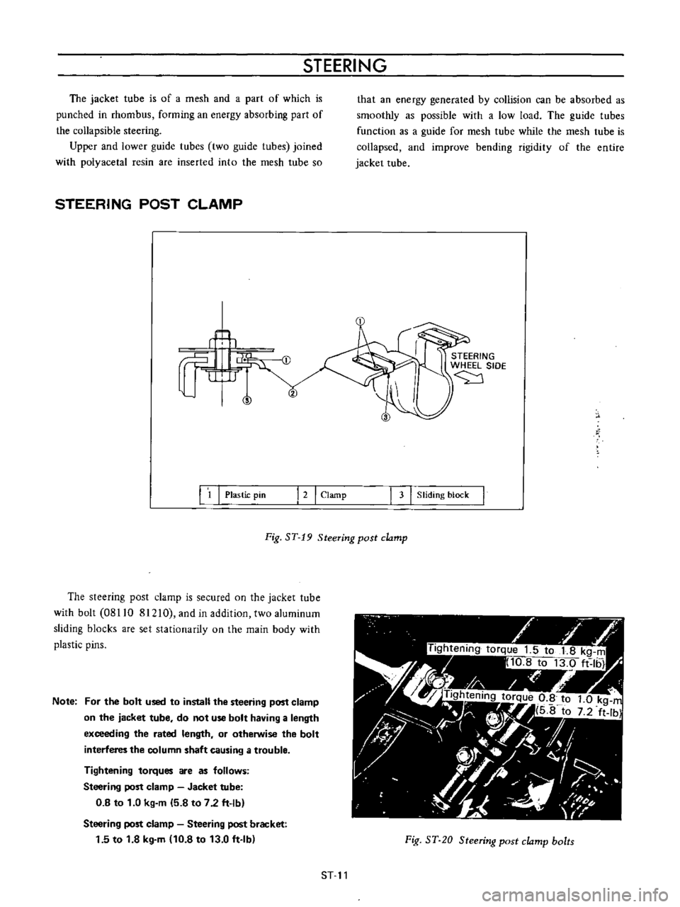
Fig
ST
19
Steering
post
clamp
The
steering
post
clamp
is
secured
on
the
jacket
tube
with
bolt
08110
81210
and
in
addition
two
aluminum
sliding
blocks
are
set
stationarity
on
the
main
body
with
plastic
pins
Note
For
the
bolt
used
to
install
the
steering
post
clamp
on
the
jacket
tube
do
not
use
bolt
having
a
length
exceeding
the
rated
length
or
otherwise
the
bolt
interferes
the
column
shaft
causing
a
trouble
Tightening
torques
are
as
follows
Steering
post
clamp
Jacket
tube
0
8
to
1
0
kg
m
5
8
to
7
2
ft
lb
Steering
post
clamp
Steering
post
bracket
1
5
to
1
8
kg
m
10
8
to
13
0
ft
Ib
Fig
ST
20
Steering
post
clamp
bolts
ST
11
Page 172 of 513
CHASSIS
The
sliding
block
is
secured
on
the
steering
post
bracket
with
bolts
upper
half
of
the
steering
column
is
supported
on
the
bracket
and
thus
the
steering
post
clamp
is
installed
on
the
body
When
a
large
impact
is
applied
from
the
driver
side
the
plastic
pins
are
cut
off
and
leaving
the
sliding
block
in
the
steering
post
bracket
side
the
clamp
proper
is
disengaged
downward
together
with
the
jacket
tube
For
any
force
applied
from
front
direction
of
the
vehicle
the
steering
post
clamp
sliding
block
does
not
move
rearward
This
construction
is
called
One
way
slide
system
and
with
this
construction
projection
of
the
column
shaft
toward
the
driver
is
prevented
completely
COLUMN
BEARING
b
ciJ
STEERING
WHEEL
SIDE
1
Jacket
tube
2
Washer
3
Snap
ring
4
Column
bush
5
ColurtlO
shaft
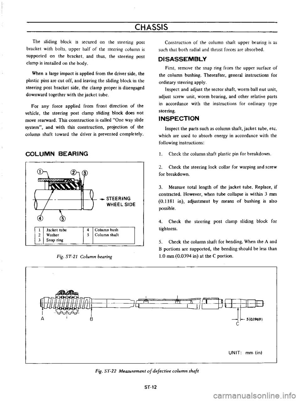
Fig
ST
21
Column
bearing
Construction
of
the
column
shaft
upper
bearing
is
as
such
that
both
radial
and
thrust
forces
are
absorbed
DISASSEMBLY
First
remove
the
snap
ring
from
the
upper
surface
of
the
column
bushing
Thereafter
general
instructions
for
ordinary
steering
apply
Inspect
and
adjust
the
sector
shaft
worm
ball
nut
unit
adjust
screw
unit
worm
bearing
and
other
relative
parts
in
accordance
with
the
instructions
for
ordinary
type
steering
INSPECTION
Inspect
the
parts
such
as
column
shaft
jacket
tube
etc
which
are
used
to
absorb
energy
in
accordance
with
the
following
instructions
Check
the
column
shaft
plastic
pin
for
breakdown
2
Check
the
steering
lock
collar
for
warping
and
screw
for
breakdown
3
Measure
tolal
length
of
the
jacket
tube
Replace
if
contracted
However
when
tube
collapse
is
within
3
mm
0
1181
in
adjustmenl
by
means
of
bushing
is
also
possible
4
Check
the
steering
post
clamp
sliding
block
for
tightness
5
Check
the
column
shaft
for
bending
When
the
A
and
B
portions
are
supported
the
bending
should
be
less
than
1
0
mm
0
0394
in
at
the
C
portion
I
l
j
B
H
I
I
lO
J
L
5
0
1969
C
J6
A
UNIT
mm
in
Fig
ST
22
Measurement
of
defective
column
shafr
ST
12
Page 177 of 513
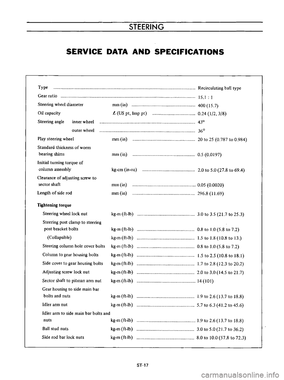
STEERING
SERVICE
DATA
AND
SPECIFICATIONS
Type
Gear
ratio
Steering
wheel
diameter
Oil
capacity
Steering
angle
inner
wheel
outer
wheel
Play
steering
wheel
Standard
thickness
of
worrn
bearing
shims
Initial
turning
torque
of
column
assembly
Clearance
of
adjusting
screw
to
sector
shaft
Length
of
side
rod
Tightening
torque
Steering
wheel
lock
nut
Steering
post
clamp
to
steering
post
bracket
bolls
Collapsible
Steering
column
hole
cover
bolts
Column
to
gear
housing
bolts
Side
cover
to
gear
housing
bolts
Adjusting
screw
lock
nut
Sector
shaft
to
pitman
arm
nut
Gear
housing
to
side
main
bar
bolts
and
nuts
Idler
arm
nut
Recirculating
ball
type
mm
in
L
US
pt
Imp
pt
15
I
I
400
157
0
24
I
2
3
8
430
360
mm
in
20
to
25
0
787
to
0
984
mm
in
0
5
0
0197
kg
em
in
oz
2
0
to
5
0
27
8
to
69
4
mrn
in
mm
in
0
05
0
0020
296
8
11
69
kg
m
ft
lb
3
0
to
3
5
217
to
25
3
kg
m
ft
lb
kg
m
ft
Ib
kg
m
ft
lb
kg
m
ft
lb
kg
m
ft
lb
kg
m
ft
lb
kg
m
ft
lb
0
8
to
1
0
5
8
to
7
2
1
5
to
1
8
10
8
to
13
0
8
to
1
0
5
8
to
7
2
1
5
to
2
5
10
8
to
18
1
I
7
to
2
8
12
3
to
20
2
2
0
to
3
0
14
5
to
21
7
14
101
kg
m
ft
lb
kg
m
ft
lb
1
9
to
2
6
13
7
to
18
8
57
to
6
3
41
2
to
45
6
Idler
arm
to
side
main
bar
bolts
and
nuts
kg
m
ft
Ib
Ball
stud
nuts
kg
m
ft
lb
Side
rod
bar
lock
nuts
kg
m
ft
lb
1
9
to
2
6
13
7
to
18
8
3
0
to
5
0
21
7
to
36
2
8
0
to
10
0
57
8
to
72
3
ST
17
Page 178 of 513
CHASSIS
TROUBLE
DIAGNOSES
AND
CORRECTIONS
Condition
Heavy
steering
Loose
steering
PuU
to
one
side
Steering
shock
Probable
cause
Low
tire
pressure
Incorrect
front
wheel
alignment
Lack
of
lubricant
Firm
sticking
of
the
ball
joint
and
strut
bearing
Improper
adjustment
and
damage
of
steering
gear
housing
Hard
locking
of
column
bearing
Incorrect
front
wheel
bearing
adjustment
Loose
steering
linkage
connections
Loose
steering
gear
housing
mounting
Incorrect
adjustment
of
adjust
nut
Incorrect
tire
pressure
Incorrect
front
wheel
alignment
Incorrect
front
wheel
bearing
adjustment
Unequal
brake
adjustment
Weak
front
suspension
units
Deformation
or
improper
fitting
of
sus
pension
Incorrect
front
wheel
alignment
Loose
front
wheel
bearings
Loose
steering
linkage
connection
and
trans
verse
link
Incorrect
adjustment
of
ball
nut
Wheels
out
of
balance
ST
18
Corrective
action
Inflate
tires
to
recommended
pressure
Adjust
to
specifications
Lubricate
steering
gear
and
ball
joints
or
replace
worn
ball
joint
Replace
Adjust
or
replace
according
to
instructions
Lubricate
with
bearing
grease
Adjust
or
replace
as
required
Inspect
replace
worn
parts
if
any
and
tighten
nuts
to
recommended
torque
Tighten
mounting
bolts
to
proper
torque
Adjust
according
to
instructions
Inflate
to
recommended
pressure
Inspect
and
correct
front
wheel
alignment
Adjust
bearings
according
to
instructions
Adjust
brakes
Replace
Check
correct
or
replace
Inspect
and
correct
front
wheel
alignment
Adjust
bearings
Inspect
replace
worn
parts
if
any
and
tighten
nuts
to
proper
torque
Adjust
steering
gear
according
to
in
structions
Inspect
and
correct
wheel
balance
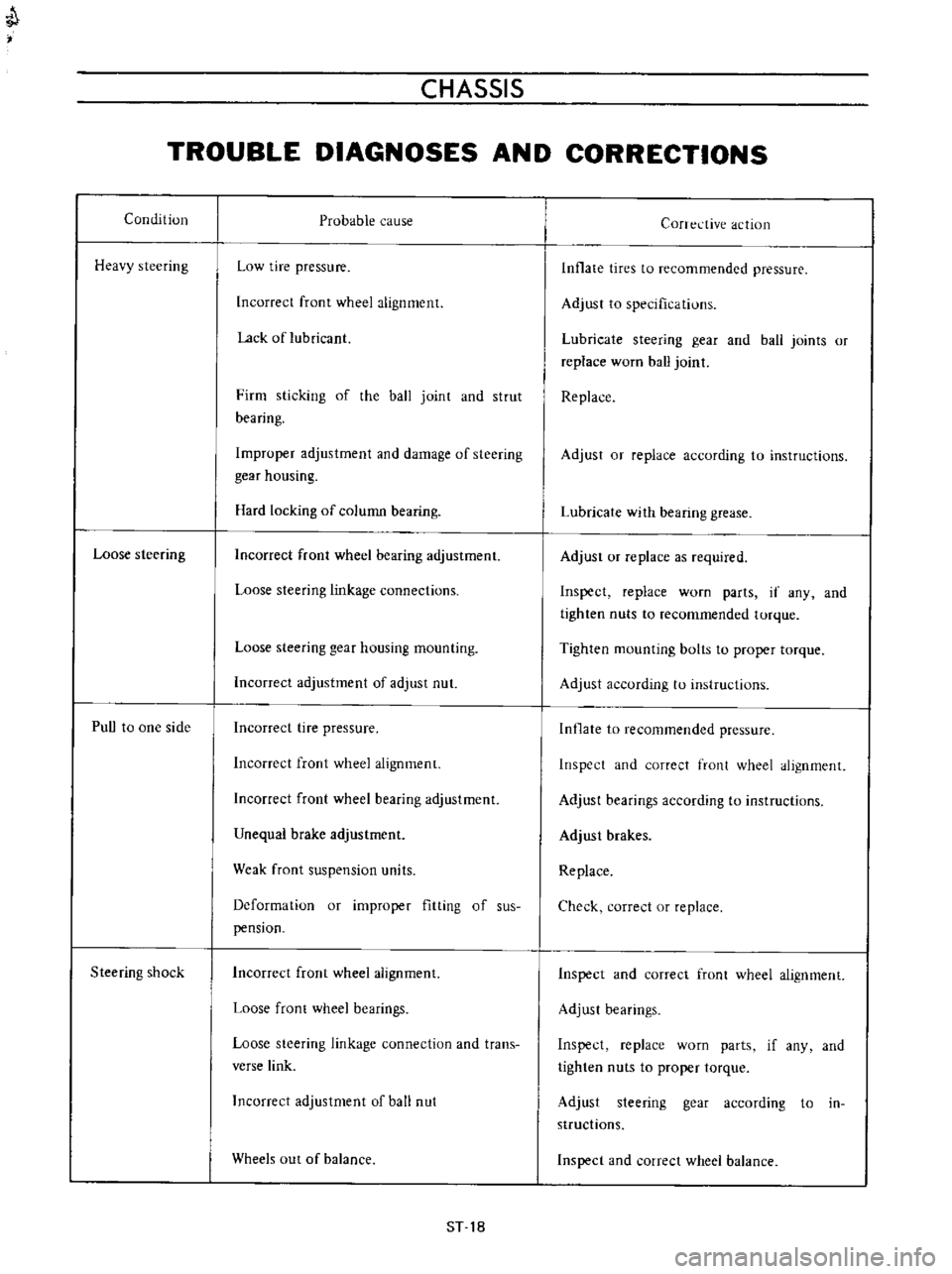
Page 181 of 513
CHASSIS
Description
The
accelerator
linkage
is
lightv
eighL
and
onstfuction
is
such
that
the
linkage
operates
smoothly
and
is
unaffected
bv
engine
vibration
Adjustment
Play
of
accelerator
wire
I
Install
the
pedal
arm
side
securely
with
a
spring
clamp
2
Set
the
dash
board
side
Quter
case
stationarily
with
a
cap
nut
Do
not
set
the
carburetor
side
adjusting
unit
stationarily
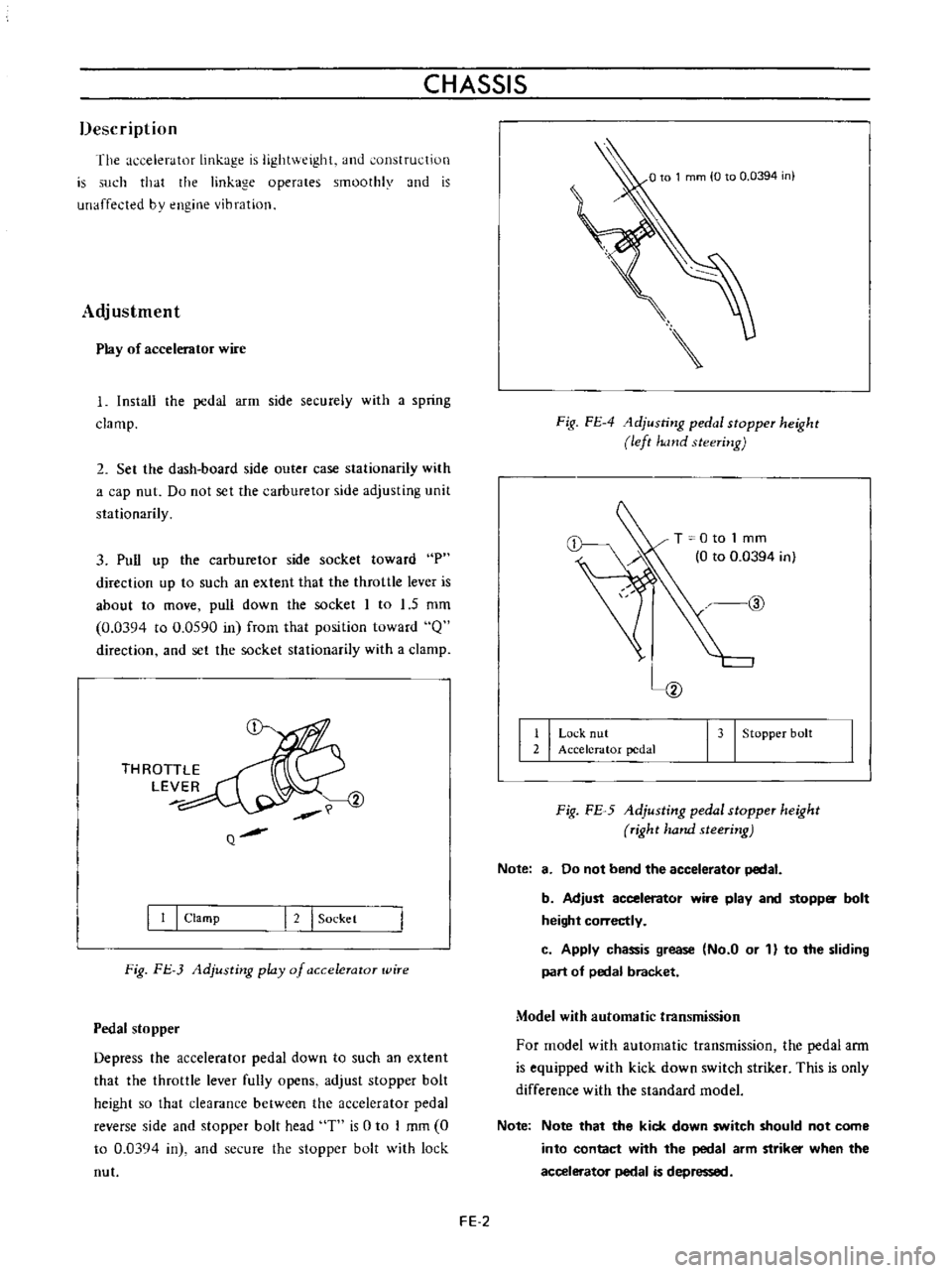
3
Pull
up
the
carburetor
side
socket
toward
P
direction
up
to
such
an
extent
that
the
throttle
lever
is
about
to
move
pull
down
the
socket
I
to
1
5
mm
0
0394
to
0
0590
in
frorn
that
position
toward
Q
direction
and
set
the
socket
stationarily
with
a
clamp
THROTTLE
LEVER
Q
I
I
I
Clamp
I
2
I
Sockel
Fig
FJ
3
Adjusting
play
of
a
ccelerator
wire
Pedal
stopper
Depress
the
accelerator
pedal
down
to
such
an
extent
that
the
throttle
lever
fully
opens
adjust
stopper
bolt
height
so
that
clearance
between
the
accelerator
pedal
reverse
side
and
stopper
bolt
head
T
is
0
to
I
mm
0
to
0
03Q4
in
and
secure
the
stopper
bolt
with
lock
nut
Fig
FE
4
1djusting
pedal
stopper
height
left
hand
steering
T
0
to
1
mm
0
to
0
0394
in
@
I
I
Lo
k
nut
2
Accelerator
pedal
I
3
I
Stopper
bolt
Fig
FE
5
Adjusting
pedal
stopper
height
right
hand
steering
Note
8
Do
not
bend
the
accelerator
pedal
b
Adjust
accelerator
wire
play
and
stopp
bolt
height
correctly
c
Apply
chassis
grease
No
a
or
1
to
the
sliding
part
of
pedal
bracket
Model
with
automatic
transmission
For
model
with
automatic
transmission
the
pedal
ann
is
equipped
with
kick
down
switch
striker
This
is
only
difference
with
the
standard
model
Note
Note
that
the
kick
down
switch
should
not
come
into
contact
with
the
pedal
arm
striker
when
the
accelerator
pedal
is
depressed
FE
2