Page 491 of 513

CHASSIS
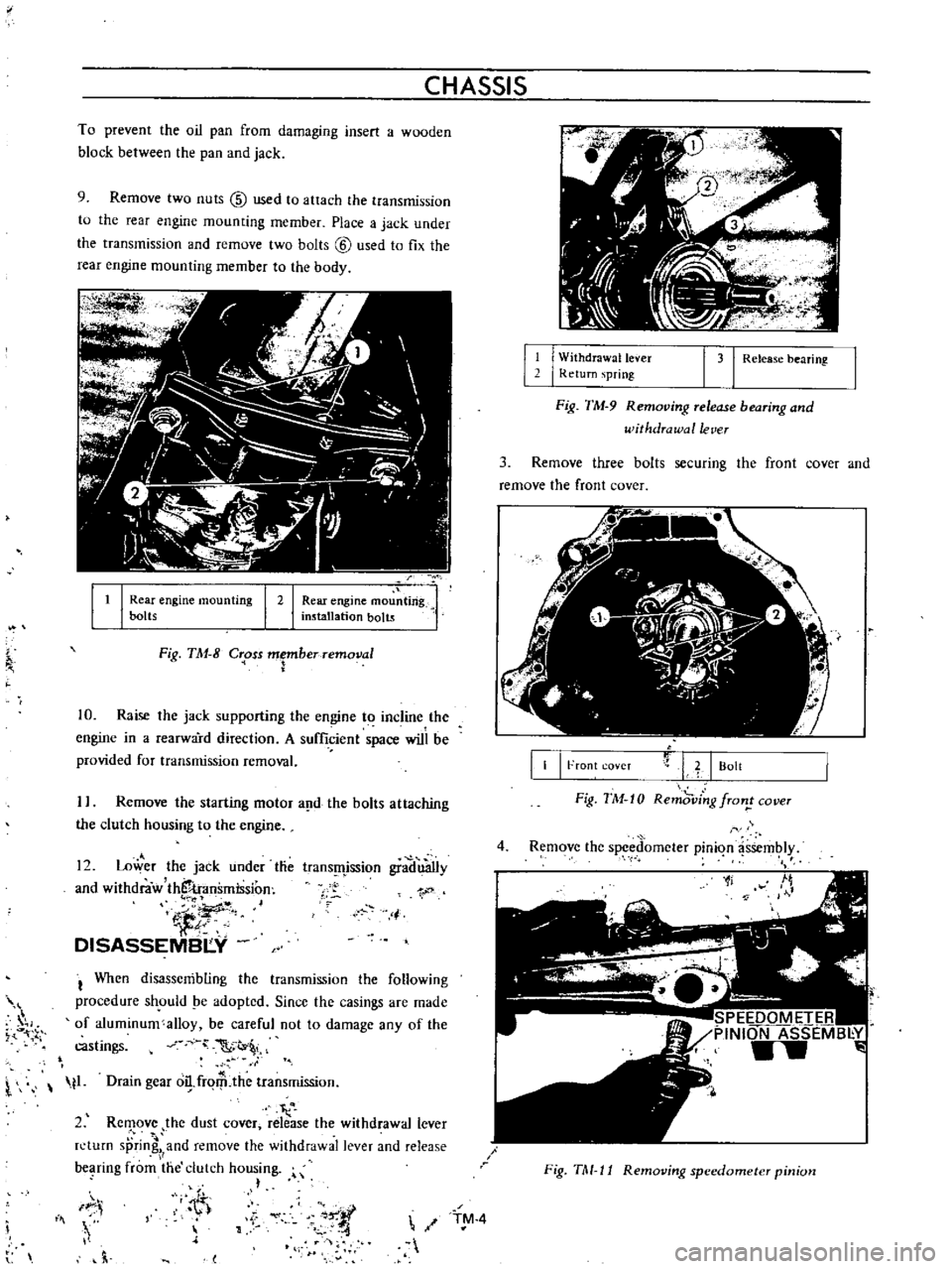
To
prevent
the
oil
pan
from
damaging
insert
a
wooden
block
between
the
pan
and
jack
9
Remove
two
nuts
@
used
to
attach
the
transmission
to
the
rear
engine
mounting
member
Place
a
jack
under
the
transmission
and
remove
two
bolts
@
used
to
fix
the
rear
engine
mounting
member
to
the
body
It
I
Rear
engine
mou
ting
installation
bolts
I
Rear
engine
mounting
bolts
I
2
Fig
TM
8
C
oss
Fberremoval
10
Raise
the
jack
supporting
the
engine
to
incline
the
engine
in
a
rearward
direction
A
sufficient
space
will
be
provided
for
transmission
removal
I
Remove
the
starting
motor
a
d
the
bolts
attaching
the
clutch
housing
to
the
engine
12
Lower
the
jack
under
tlie
and
withdraw
thS
transmission
iJ
DISASSEMBI
Y
trans
fljssion
gradu3Ily
1
j
I
When
disassembling
the
transmission
the
following
procedure
sh
ould
pe
adopted
Since
the
casings
are
made
of
aluminum
alloy
be
careful
not
to
damage
any
of
the
castings
C
t
l
t1
Drain
gear
o
frqrP
the
transmission
I
2
Rc
ove
the
dust
cover
release
the
withdrawal
lever
n
turn
sprin
and
remove
the
withdrawal
lever
and
release
bC
lring
from
the
clutch
housing
h
IF
i
Iii
h
l
11
I
W
ithdrawallever
I
Return
spring
1
31
Release
bearing
Fig
TM
9
Removing
release
bearing
and
withdrawal
lever
3
Remove
three
bolts
securing
the
front
cover
and
remove
the
front
cover
II
I
Front
coveT
L
I
Bolt
Fig
TM
10
Remd
ving
fron
cover
4
Remove
the
spced
omcter
pinion
assembly
1f
SPEEDOMETER
PINION
ASSEMB
Y
w
Fig
TM
11
Removing
speedometer
pinion
TM
4
Page 500 of 513

j
TRANSMISSION
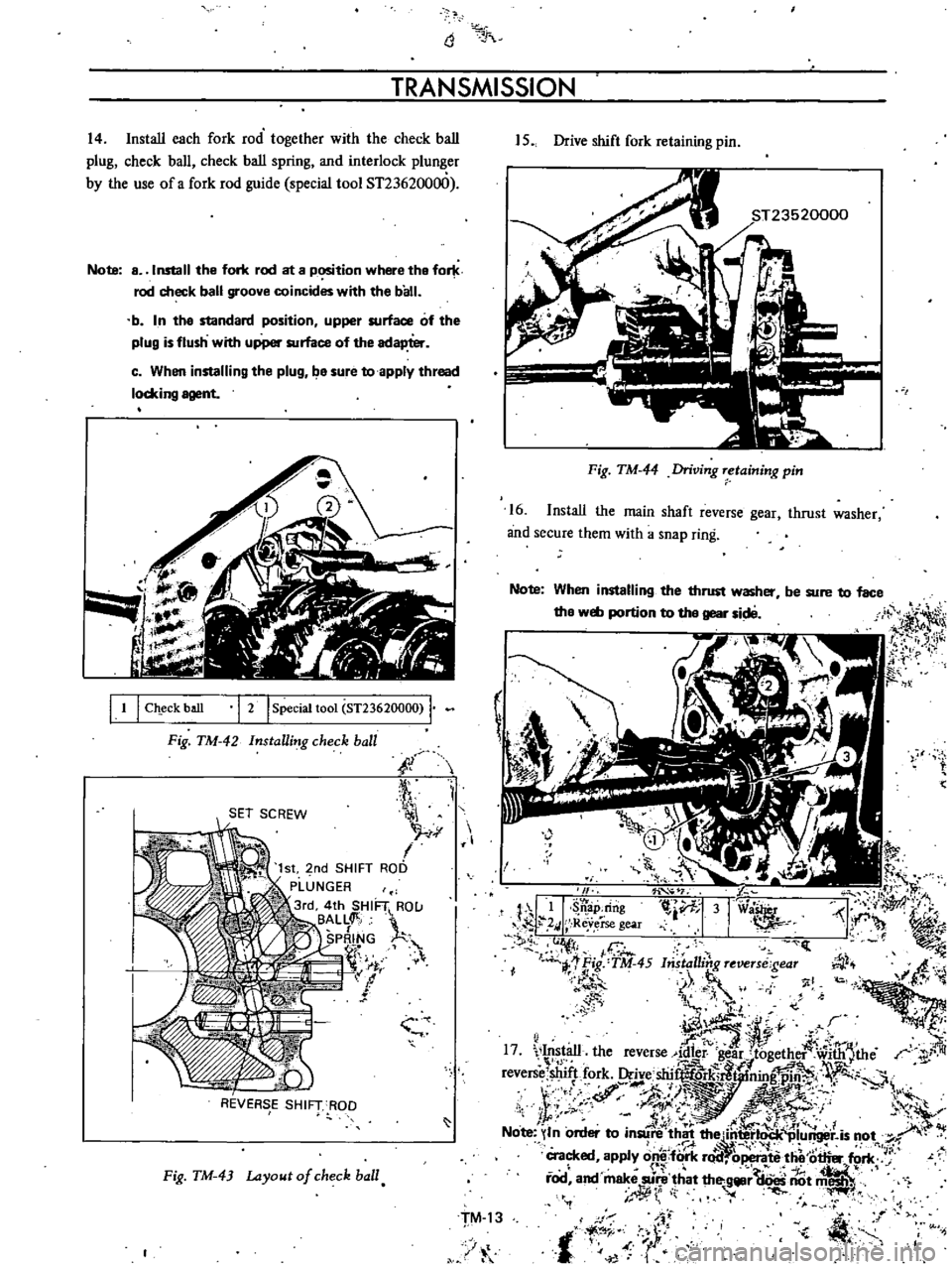
14
Install
each
fork
rod
together
with
the
check
ball
plug
check
ball
check
ball
spring
and
interlock
plu
er
by
the
use
of
a
fork
rod
guide
special
tool
ST236200
0
Note
a
Install
the
fori
rod
at
a
p
tion
where
tha
for
rod
check
ball
groove
coincides
with
the
ball
b
In
tha
standard
position
upper
surface
of
the
plug
is
flush
with
upper
surface
of
the
adapter
c
When
installing
the
plug
ba
sure
to
apply
thread
locking
agent
I
1
I
Ch
eck
ball
I
2
I
Special
toot
ST23620000
Fig
TM
42
InstaUing
check
ball
i
l
SET
SCREW
J
r
r
I
1st
2nd
SHIFT
ROD
PLUNGER
3rd
4th
SHIF1
RO
U
BALL
lt
SPRING
r
if
If
f
J
REVERSE
SHIFT
ROD
Fig
TM
43
Layout
of
check
ball
15
Drive
shift
fork
retaining
pin
Fig
TM
44
Driving
retaining
pin
16
Install
the
main
shaft
reverse
gear
thrust
washer
and
secure
them
with
a
snap
ring
Note
When
installing
the
thrust
washer
tha
web
portion
to
the
gear
sid8
be
sure
to
face
I
J
ll
it
ij
I
r
7
I
t
Lt
l
i
JI
h
l
p
II
Si
ap
dng
l
iVf
31
via
I
i
i
2
I
Reverse
gear
rll
f
F
O
1
Ii
ct
I
C
I
jf
1
Fig
TM
45
bista
ling
reveTS
gear
fJ
i
tJ
i
J
I
1
i
4
1
a
ot
j
l
i1i
o
f
tJ
r
w
i6
J
t
F
I
f
1
it
IV
I
17
1
t
1
the
reverse
@Isr
e
r
tilgether
wi1
tJthe
r
shift
k
Oc
shi
k
7i
fN
revers
lO
r
r
1
mg
1
1
f
i
J
4t
z
1
if
f
St
J
f
l
p
t
A
J
t
M
ff
J
1
A
Note
In
order
to
in
re
t
1h
f
t
li
u
r
is
O
cracked
apply
onl
fo
rk
r
id
ope
te
thet6t1ier
fori
J
t
i
fod
an
make
sU
r
e
that
th
gljllr
aoes
nOt
miiSli
J
o
I
t
J
t
if
z
TM
13
1
t
Page 509 of 513

CHASSIS
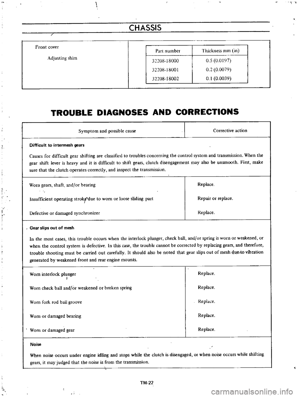
Front
cover
Part
number
Thickness
mm
Un
Adjusting
shim
32208
18000
32208
18001
32208
18002
0
5
0
0197
0
2
0
0079
0
1
0
0039
TROUBLE
DIAGNOSES
AND
CORRECTIONS
Symptom
and
possible
cause
Corrective
action
Difficult
to
intermesh
gears
Causes
for
difficult
gear
shifting
are
classified
to
troubles
concerning
the
control
system
and
transmission
When
the
gear
shift
lever
is
heavy
and
it
is
difficult
to
shift
gears
clutch
disengagement
may
also
be
unsmooth
First
make
sure
that
the
clutch
operates
correctly
and
inspect
the
transmission
Worn
gears
shaft
and
or
bearing
Replace
Insufficient
operating
strokfdue
to
wom
or
loose
sliding
part
Repair
or
replace
Defective
or
damaged
synchronizer
Replace
Gear
slips
out
of
mesh
In
the
most
cases
this
trouble
occurs
when
the
interlock
plunger
check
ball
and
or
spring
is
wuro
or
weakened
or
when
the
control
system
is
defective
In
this
case
the
trouble
cannot
be
corrected
by
replacing
gears
and
therefure
trouble
shooting
must
be
carried
out
carefully
It
should
also
be
noted
that
gear
slips
out
of
mesh
due
to
vibration
generated
by
weakened
front
and
rear
engine
mounts
Worn
interlock
plunger
1
Replace
Worn
check
ball
and
or
weakened
or
broken
spring
Replace
Worn
fork
rod
ball
groove
Replace
Worn
or
damaged
bearing
Replace
Worn
or
damaged
gear
Replace
Noise
When
noise
occurs
under
engine
idling
and
stops
while
the
clutch
is
disengaged
or
when
noise
occurs
while
shifting
gears
it
may
judged
that
the
noise
is
from
the
transmissiun
TM
22