1973 DATSUN B110 lock
[x] Cancel search: lockPage 408 of 513

FUEL
SYSTEM
c
Oke
valve
1
Or
Rubber
band
Fig
EF
2B
Adjusting
choke
unloadeT
Hi
metal
setting
Measurement
of
bi
metal
heater
resistance
Install
the
bi
metal
cover
in
place
on
the
carburetor
Make
sure
that
the
resistance
across
the
terminal
and
the
carburetor
body
is
in
the
range
from
8
6
to
9
0
ohms
Measure
the
resistance
without
electric
current
through
the
heater
and
at
about
210e
700F
Note
Use
an
accurate
measuring
instrument
such
as
a
wheatstone
bridge
2
Bi
metal
cover
setting
Position
the
hi
metal
cover
until
the
index
mark
is
aligned
at
the
middle
point
of
the
scale
Note
When
somewhat
over
choked
set
bi
metal
cover
after
turning
it
clockwise
slightly
Fig
EF
29
Setting
hi
metal
cover
EF
17
Page 409 of 513
ENGINE
Adjustment
of
interlock
opening
of
primary
and
secondary
throttle
valves
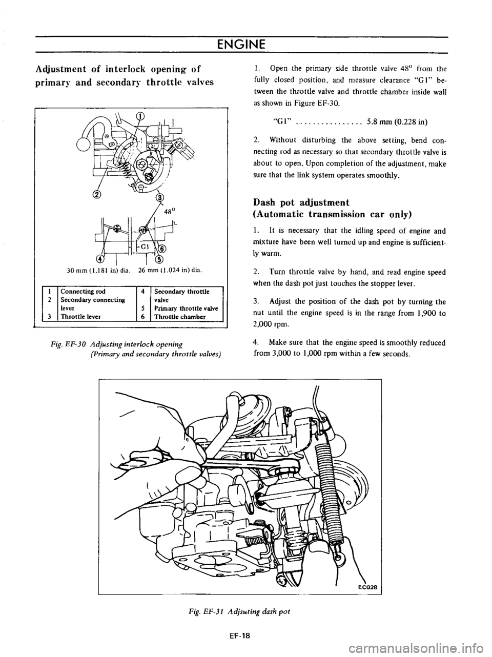
Open
the
primary
side
throttle
valve
480
from
the
fully
closed
position
and
measure
clearance
G
1
be
tween
the
throttle
valve
and
throttle
chamber
inside
wall
as
shown
in
Figure
EF
30
@I
30
rom
1
181
in
dia
Gl
5
8
mm
0
228
in
I
V
2
Without
disturbing
the
above
setting
bend
con
necting
rod
as
necessary
so
that
secondary
throttle
valve
is
about
to
open
Upon
completion
of
the
adjustment
make
sure
that
the
link
system
operates
smoothly
2
Dash
pot
adjustment
Automatic
transmission
car
only
It
is
necessary
that
the
idling
speed
of
engine
and
mixture
have
been
weB
turned
up
and
engine
is
sufficient
Iywarm
2
Turn
throttle
valve
by
hand
and
read
engine
speed
when
the
dash
pot
just
touches
the
stopper
lever
1
Connecting
rod
2
Secondary
connecting
lever
3
Throttle
lever
4
Secondary
throttle
valve
5
Primuy
throttle
valve
6
Throttle
chamber
3
Adjust
the
position
of
the
dash
pot
by
turning
the
nut
until
the
engine
speed
is
in
the
range
from
1
900
to
2
000
rpm
Fig
EF
30
Adjusting
interlock
opening
Primary
and
secondary
throttle
valves
4
Make
sure
that
the
engine
speed
is
smoothly
reduced
from
3
000
to
1
000
rpm
within
a
few
seconds
Fig
EF
1
Adjsuting
dash
pot
EF
18
Page 411 of 513
ENGINE
Y
Q
0
Fig
EF
34
Disassembling
accelerator
pump
and
hi
metal
cover
1
EC013
Fig
EF
35
Removing
throttle
chamber
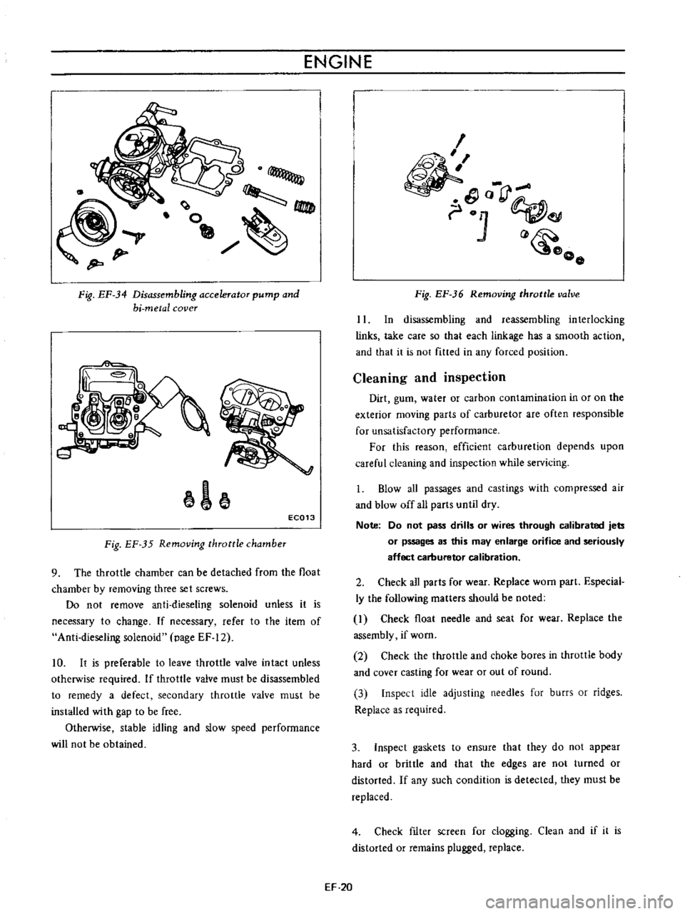
9
The
throttle
chamber
can
be
detached
from
the
float
chamber
by
removing
three
set
screws
Do
not
remove
anti
dieseling
solenoid
unless
it
is
necessary
to
change
If
necessary
refer
to
the
item
of
Anti
dieseling
solenoid
page
EF
12
10
It
is
preferable
to
leave
throttle
valve
intact
unless
otherwise
required
If
throttle
valve
must
be
disassembled
to
remedy
a
defect
secondary
throttle
valve
must
be
installed
with
gap
to
be
free
Otherwise
stable
idling
and
slow
speed
performance
will
not
be
obtained
I
o
rJ
01
o
o
Fig
EF
36
Removing
throttle
valve
II
In
disassembling
and
reassembling
interlocking
links
take
care
so
that
each
linkage
has
a
smooth
action
and
that
it
is
not
fitted
in
any
forced
position
Cleaning
and
inspection
Dirt
gum
water
or
carbon
contamination
in
or
on
the
exterior
moving
parts
of
carburetor
are
often
responsible
for
unsatisfactory
performance
For
this
reason
efficient
carburetion
depends
upon
careful
cleaning
and
inspection
while
servicing
1
Blow
aU
passages
and
castings
with
compressed
air
and
blow
off
all
parts
until
dry
Note
Do
not
pass
drills
or
wires
through
calibrated
jets
or
pssages
as
this
may
enlarge
orifice
and
seriously
affect
carburetor
calibration
2
Check
all
parts
for
wear
Replace
worn
part
Especial
ly
the
following
matters
should
be
noted
I
Check
float
needle
and
seat
for
wear
Replace
the
assembly
if
worn
2
Check
the
throttle
and
choke
bores
in
throttle
body
and
cover
casting
for
wear
or
out
of
round
3
Inspect
idle
adjusting
needles
fur
burrs
or
ridges
Replace
as
required
3
Inspect
gaskets
to
ensure
that
they
do
not
appear
hard
or
brittle
and
that
the
edges
are
not
turned
or
distorted
If
any
such
condition
is
detected
they
must
be
replaced
4
Check
fIlter
screen
for
clogging
Clean
and
if
it
is
distorted
or
remains
plugged
replace
EF
20
Page 412 of 513
FUEL
SYSTEM
5
Check
venturi
clusters
for
loose
or
worn
parts
If
damage
or
looseness
exists
replace
cluster
assembly
6
Check
the
linkage
for
operating
condition
7
Inspect
the
operation
of
accelerating
pump
Pour
gasoline
into
the
float
chamber
and
operate
the
throttle
lever
Check
condition
of
gasoline
injection
from
the
accelerating
nozzle
Assembly
and
instalIetion
Assemble
and
install
the
carburetor
in
reverse
sequence
of
disassembly
and
removal
Replace
the
gaskets
if
necessary
When
disassembling
and
reassembling
the
interlock
link
and
related
components
be
careful
not
to
bend
or
deform
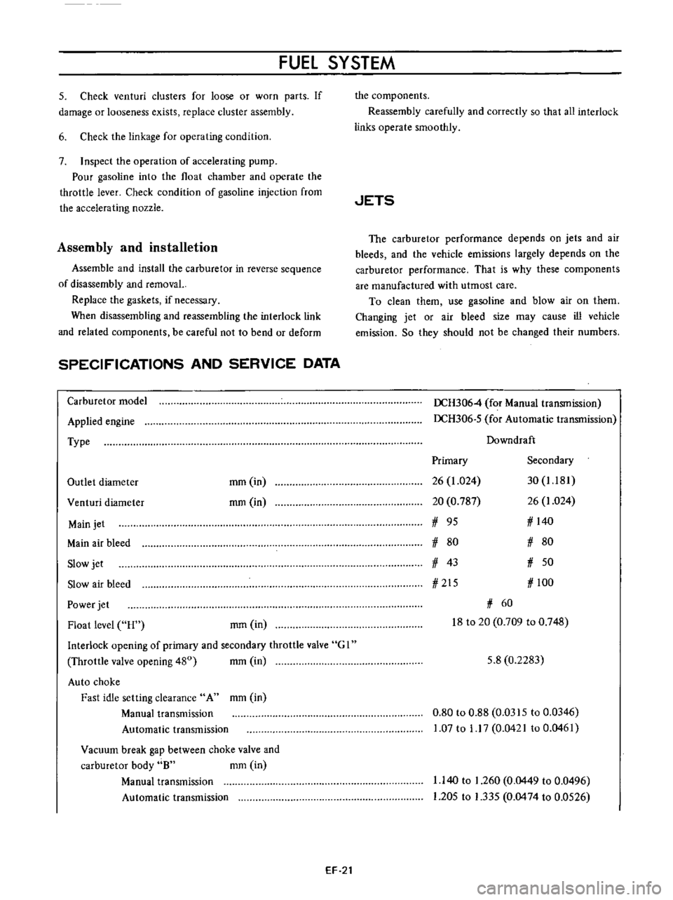
SPECIFICATIONS
AND
SERVICE
DATA
Carburetor
model
Applied
engine
Type
Outlet
diameter
mm
in
rom
in
Venturi
diameter
Main
jet
Main
air
bleed
Slow
jet
Slow
air
bleed
Power
jet
Float
level
H
rom
in
Interlock
opening
of
primary
and
secondary
throttle
valve
G
I
Throttle
valve
opening
480
mm
in
Auto
choke
Fast
idle
setting
clearance
A
mm
in
Manual
transmission
Automatic
transmission
Vacuum
break
gap
between
choke
valve
and
carburetor
body
8
mm
in
Manual
transmission
Automatic
transmission
EF
21
the
components
Reassembly
carefully
and
correctly
so
that
all
interlock
links
operate
smoothly
JETS
The
carburetor
performance
depends
on
jets
and
air
bleeds
and
the
vehicle
emissions
largely
depends
on
the
carburetor
performance
That
is
why
these
components
are
manufactured
with
utmost
care
To
clean
them
use
gasoline
and
blow
air
on
them
Changing
jet
or
air
bleed
size
may
cause
ill
vehicle
emission
So
they
should
not
be
changed
their
numbers
DCH3064
for
Manual
transmission
DCH306
5
for
Automatic
transmission
Downdraft
Primary
Secondary
26
1
024
30
1
181
20
0
787
26
1
024
1
95
1
140
1
80
1
80
1
43
1
50
1
215
1
100
1
60
18
to
20
0
709
to
0
748
5
8
0
2283
0
80
to
0
88
0
0315
to
0
0346
1
07
to
1
17
0
0421
to
0
0461
1
140
to
1
260
0
0449
to
0
0496
1
205
to
1
335
0
0474
to
0
0526
Page 417 of 513
ENGINE
ffi68
mmAq
14
5
mAq
3
way
connector
Cock
II
M
nam
e
Flow
guide
valve
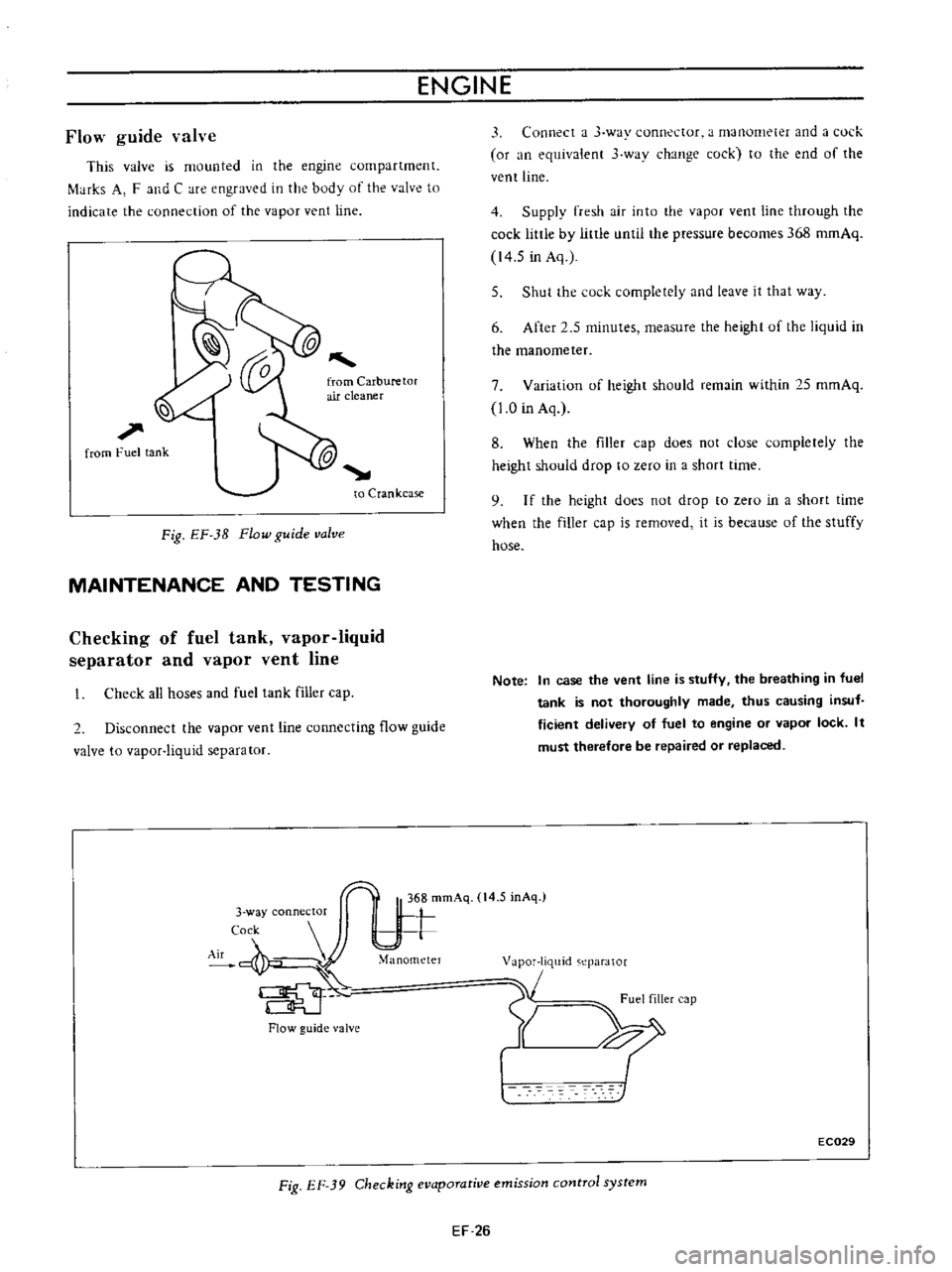
This
valve
is
mounted
in
the
engine
compartment
f
tHks
A
F
and
C
are
engraved
in
the
body
of
the
valve
to
indicate
the
connection
of
the
vapor
vent
line
l
l
1
from
Fuel
tank
to
Crankcase
Fig
EF
3B
Flow
guide
valve
MAINTENANCE
AND
TESTING
Checking
of
fuel
tank
vapor
liquid
separator
and
vapor
vent
line
Check
all
hoses
and
fuel
tank
filler
cap
2
Disconnect
the
vapor
vent
line
connecting
flow
guide
valve
to
vapor
liquid
separator
Flow
guide
valve
3
Connect
a
J
way
connector
a
manometer
and
a
l
ul
k
or
an
equivalent
3
wav
change
cock
to
the
end
of
the
vent
line
4
Supply
fresh
air
into
the
vapor
vent
line
through
the
cock
little
by
little
until
the
pressure
becomes
368
romAq
14
5
in
Aq
5
Shut
the
cock
completely
and
leave
it
that
way
6
After
2
5
minutes
measure
the
height
uf
the
liquid
in
the
manometer
7
Variation
of
height
should
remain
within
25
mmAq
1
0
in
Aq
8
When
the
filler
cap
does
not
close
completely
the
height
should
drop
to
zero
in
a
short
time
9
I
f
the
height
docs
not
drop
to
zero
in
a
short
time
when
the
filler
cap
is
removed
it
is
because
of
the
stuffy
hose
Note
In
case
the
vent
line
is
stuffy
the
breathing
in
fuel
tank
is
not
thoroughly
made
thus
causing
insuf
ficient
delivery
of
fuel
to
engine
or
vapor
lock
It
must
therefore
be
repaired
or
replaced
1
m
eparator
1
Fuel
filler
cap
Y
XI
EC029
Fig
EF
39
Checking
evaporative
emission
control
system
EF
26
Page 429 of 513
ENGINE
ElECTRICAL
SYSTEM
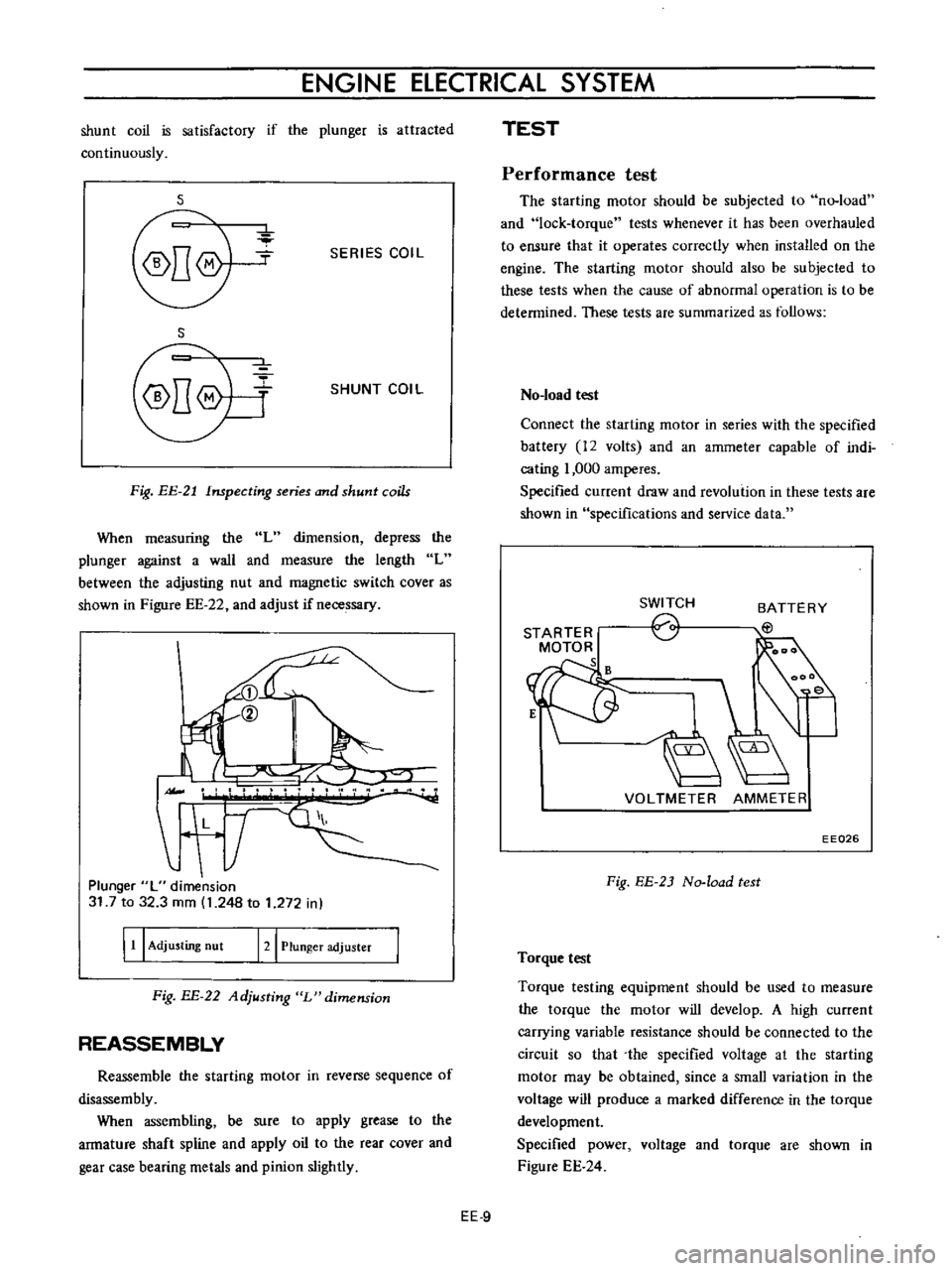
shunt
coil
is
satisfactory
if
the
plunger
is
attracted
continuously
s
SERIES
COIL
S
SHUNT
COIL
Fig
EE
21
Inspecting
series
and
shunt
coils
When
measuring
the
L
dimension
depress
the
plunger
against
a
wall
and
measure
the
length
L
between
the
adjusting
nut
and
magnetic
switch
cover
as
shown
in
Figure
EE
22
and
adjust
if
necessary
II
L
T
Plunger
L
dimension
31
7
to
32
3
mm
1
248
to
1
272
in
I
11
I
Adjusting
nut
121
Plunger
adjuster
Fig
BE
22
Adjusting
L
dimension
REASSEMBLY
Reassemble
the
starting
motor
in
reverse
sequence
of
disassembly
When
assembling
be
sure
to
apply
grease
to
the
armature
shaft
spline
and
apply
oil
to
the
rear
cover
and
gear
case
bearing
metals
and
pinion
slightly
TEST
Performance
test
The
starting
motor
should
be
subjected
to
no
load
and
lock
torque
tests
whenever
it
has
been
overhauled
to
ensure
that
it
operates
correctly
when
installed
on
the
engine
The
starting
motor
should
also
be
subjected
to
these
tests
when
the
cause
of
abnormal
operation
is
to
be
determined
These
tests
are
summarized
as
follows
No
load
test
Connect
the
starting
motor
in
series
with
the
specified
battery
12
volts
and
an
ammeter
capable
of
indi
cating
1
000
amperes
Specified
current
draw
and
revolution
in
these
tests
are
shown
in
specifications
and
service
data
STARTER
MOTOR
s
SWITCH
o
BATTERY
EtJ
VOLTMETER
AMMETER
EE026
Fig
EE
2J
No
load
test
Torque
test
Torque
testing
equipment
should
be
used
to
measure
the
torque
the
motor
will
develop
A
high
current
carrying
variable
resistance
should
be
connected
to
the
circuit
so
that
the
specified
voltage
at
the
starting
motor
may
be
obtained
since
a
small
variation
in
the
voltage
will
produce
a
marked
difference
in
the
torque
development
Specified
power
voltage
and
torque
are
shown
in
Figure
EE
24
EE
9
Page 443 of 513
Charge
relay
SPECIFICATIONS
AND
SERVICE
DATA
TROUBLE
DIAGNOSES
AND
CORRECTIONS
ENGINE
ElECTRICAL
SYSTEM
Reduction
limit
Repair
limit
Repair
accuracy
mm
in
mm
in
mm
in
REGULATOR
CONTENTS
DESCRIPTiON
MEASUREMENT
OF
REGULATING
VOLTAGE
ADJUSTMENT
Voltage
regu
lator
EE
23
EE
24
EE
25
EE
25
DESCRIPTION
I
0
0394
0
3
0
0118
0
05
0
0197
EE
26
EE
26
EE
27
1
I
T
r
@
V
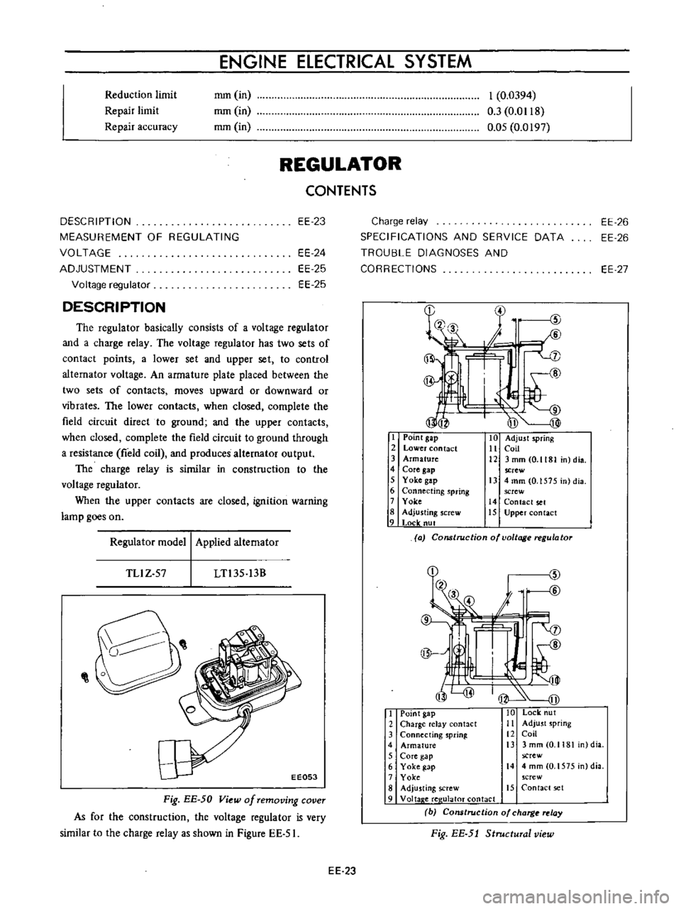
The
regulator
basically
consists
of
a
voltage
regulator
and
a
charge
relay
The
voltage
regulator
has
two
sets
of
contact
points
a
lower
set
and
upper
set
to
control
altemator
voltage
An
armature
plate
placed
between
the
two
sets
of
contacts
moves
upward
or
downward
or
vibrates
The
lower
contacts
when
closed
complete
the
field
circuit
direct
to
ground
and
the
upper
contacts
when
closed
complete
the
field
circuit
to
ground
through
a
resistance
field
coil
and
produces
alternator
output
The
charge
relay
is
similar
in
construction
to
the
voltage
regulator
When
the
upper
contacts
are
closed
ignition
warning
lamp
goes
on
I
Point
gap
2
Lower
contact
3
Armature
4
Core
gap
5
Yoke
gap
6
Connecting
spring
7
Yoke
8
Adjusting
screw
9
Locle
nut
10
Adjust
spring
11
Coil
12
3mmCO
1181
n
dia
screw
13
4
mm
0
1575
in
dia
screw
14
Contact
set
15
Upper
contact
Regulator
model
Applied
alternator
a
Construction
of
voltage
regulator
TLlZ
57
LTl35
13B
I
Point
gap
10
Lock
ut
2
Charge
elay
antact
Ii
Adjust
spring
3
Connecting
sprinl
12
Coil
4
Armature
i3
3
mm
0
1181
dia
5
Core
gap
screw
6
Yoke
gap
14
4mm
O
1575
n
dia
7
Yoke
crew
8
Adju
ting
screw
15
Contact
set
9
Voltap
e
ree
ulaloT
contact
b
Cons
rue
ion
of
charg
relay
Fig
EE
5J
Structural
view
Fig
EE
50
View
of
removing
cover
As
for
the
construction
the
voltage
regulator
is
very
similar
to
the
charge
relay
as
shown
in
Figure
EE
51
EE
23
Page 445 of 513
ENGINE
ElECTRICAL
SYSTEM
Ambient
temperature
Rated
regulating
voltage
roC
OF
V
10
14
14
6
to
15
6
0
32
14
45
to
15
45
10
50
14
3
to
15
3
20
68
14
15
to
15
15
30
86
14
0
to
15
0
40
104
13
85
to
14
85
Note
8
Do
not
measure
voltage
immediately
after
driv
ing
Do
this
while
regulator
is
cold
b
To
measure
voltage
raise
engine
speed
gradual
ly
from
idling
to
rated
speed
c
Voltage
may
be
approximately
O
3V
higher
than
the
rated
for
two
to
three
minutes
after
engine
is
started
or
more
specifically
when
regulator
becomes
self
heated
Measurements
should
then
be
made
within
one
minute
after
starting
engine
or
when
regulator
is
cold
d
The
regulator
is
of
a
temperature
compensating
type
Before
measuring
voltage
be
sure
to
meas
ure
surrounding
temperature
and
correct
measure
ments
according
to
the
table
in
the
left
hand
side
ADJUSTMENT
Voltage
regulator
As
the
result
of
above
measurement
when
the
regu
lating
voltage
is
deviated
from
the
rated
value
adjust
the
regulator
in
accordance
with
the
following
instructions
I
Inspect
contact
surface
and
if
rough
lightly
polish
the
surface
with
fine
emery
paper
500
or
600
2
Measure
each
gap
and
adjust
if
necessary
Adjust
the
core
gap
and
point
gap
in
that
order
No
adjustment
is
required
for
the
yoke
gap
J
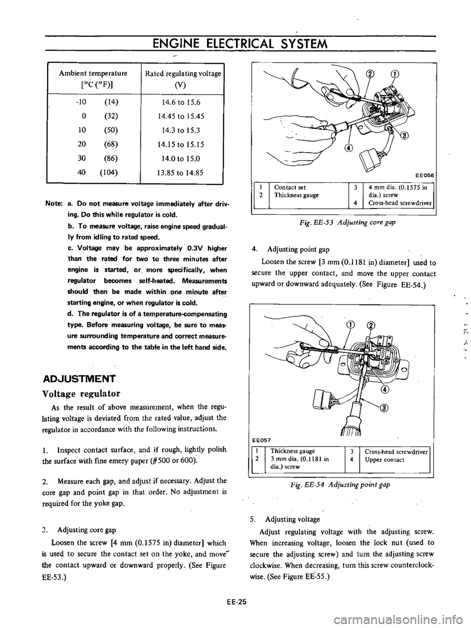
Adjusting
core
gap
Loosen
the
screw
4
mm
0
1575
in
diameter
which
is
used
to
secure
the
contact
set
on
the
yoke
and
move
the
contact
upward
or
downward
properly
See
Figure
EE
53
t
2
I
I
EE056
4
mm
dia
0
1575
in
dia
screw
Cross
head
screwdriver
Contact
set
Thickness
gauge
Fig
EE
53
Adjusting
COTe
gap
4
Adjusting
point
gap
Loosen
the
screw
3
mm
0
1181
in
diameter
used
to
secure
the
upper
contact
and
move
the
upper
contact
upward
or
downward
adequately
See
Figure
EE
54
EE057
1
Thickness
gauge
2
3
mm
dia
0
1181
in
dia
screw
3
Cross
head
screwdriver
4
Upper
con
tact
Fig
EE
54
Adjusting
point
gap
5
Adjusting
voltage
Adjust
regulating
voltage
with
the
adjusting
screw
When
increasing
voltage
loosen
the
lock
nut
used
to
secure
the
adjusting
screw
and
turn
the
adjusting
screw
clockwise
When
decreasing
turn
this
screw
counterclock
wise
See
Figure
EE
55
EE
25