1973 DATSUN B110 lock
[x] Cancel search: lockPage 307 of 513
ENGINE
operating
mechanism
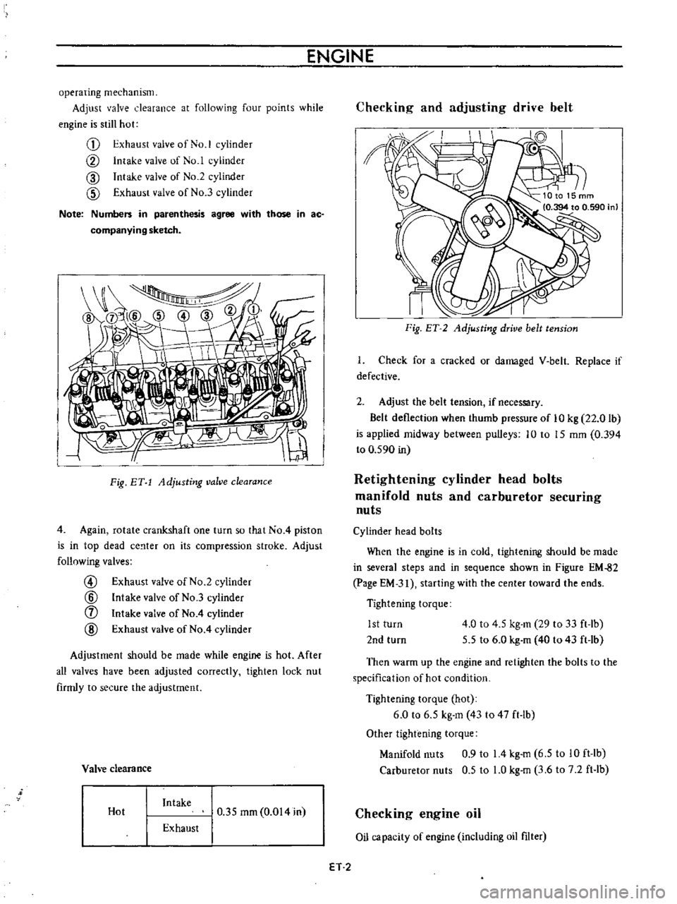
Adjust
valve
clearance
at
following
four
points
while
engine
is
still
hot
G
Exhaust
valve
of
No
1
cylinder
CV
Intake
valve
of
No
1
cylinder
CID
Intake
valve
of
No
2
cylinder
CID
Exhaust
valve
of
No
3
cylinder
Note
Numbers
in
parenthesis
agree
with
those
in
ac
companying
sketch
I
Fig
BY
1
Adjusting
valve
clearance
4
Again
rotate
crankshaft
one
turn
so
that
No
4
piston
is
in
top
dead
ce
lter
on
its
compression
stroke
Adjust
follnwing
valves
@
Exhaust
valve
of
No
2
cylinder
@
Intake
valve
of
No
3
cylinder
f
Intake
valve
of
No
4
cylinder
@
Exhaust
valve
of
No
4
cylinder
Adjustment
should
be
made
while
engine
is
hot
After
all
valves
have
been
adjusted
correctly
tighten
lock
nut
firmly
to
secure
the
adjustment
Vah
e
clearance
Hot
Intake
0
35
mm
0
014
in
Exhaust
Checking
and
adjusting
drive
belt
II
I
Fig
ET
2
Adjusting
drive
belt
tension
I
Check
for
a
cracked
or
damaged
V
belt
Replace
if
defective
2
Adjust
the
belt
tension
if
necessary
Belt
deflection
when
thumb
pressure
of
10
kg
22
0
lb
is
applied
midway
between
pulleys
10
to
15
mm
0
394
to
0
590
in
Retightening
cylinder
head
bolts
manifold
nuts
and
carburetor
securing
nuts
Cylinder
head
bolts
When
the
engine
is
in
cold
tightening
should
be
made
in
several
steps
and
in
sequence
shown
in
Figure
EM
82
page
EM
31
starting
with
the
center
toward
the
ends
Tightening
torque
1st
turn
2nd
turn
4
0
to
4
5
kg
m
29
to
33
ft
lb
5
5
to
6
0
kg
m
40
to
43
ft
lb
Then
warm
up
the
engine
and
retighten
the
bolts
to
the
specification
of
hot
condition
Tightening
torque
hot
6
0
to
6
5
kg
m
43
to
47
ft
lb
Other
tightening
torque
Manifold
nuts
0
9
to
14
kg
m
6
5
to
10
ft
lb
Carburetor
nuts
0
5
to
LO
kg
m
3
6
to
7
2
ft
lb
Checking
engine
oil
Oil
capacity
of
engine
including
oil
filter
ET
2
Page 311 of 513

ENGINE
4
Install
a
timing
light
on
No
cylinder
spark
plug
wire
and
install
a
tachometer
5
Set
idling
speed
to
approximately
800
rpm
6
Check
ignition
timing
if
it
is
50BTDC
Before
Top
of
Dead
Center
by
the
use
of
timing
light
If
necessary
adjust
it
as
follows
Loosen
set
screw
to
such
an
extent
that
distributor
can
be
moved
by
hand
2
Adjust
ignition
timing
to
50BTDC
3
Lock
distributor
set
screw
and
make
sure
that
timing
is
correct
Fig
ET
9
Checking
ignition
timing
Ignition
timing
degree
50
B
T
D
C
Checking
or
replacing
distributor
breaker
point
condenser
and
spark
plugs
Distributor
breaker
point
Check
distributot
breaker
points
for
abnormal
pitting
and
wear
Replace
if
necessary
Make
sure
they
are
in
correct
alignment
for
full
contact
and
that
point
dwell
and
gap
are
correct
Clean
and
apply
distributor
grease
to
earn
and
wick
Note
Do
not
apply
grease
excessively
Distributor
Point
gap
0
45
to
0
55
mm
0
018
to
0
Q22
in
49
to
55
degrees
Dwell
angle
ET004
Fig
ET
10
Checking
distributor
point
gap
Condenser
I
Clean
outlet
of
condenser
lead
wire
and
check
for
loose
set
screw
Retighten
if
necessary
2
Check
condenser
capacity
with
a
capacity
meter
Condenser
insulation
resistance
may
be
also
checked
using
a
tester
by
adjusting
its
range
to
measure
large
resistance
value
When
condenser
is
normal
the
tester
pointer
swings
largely
and
rapidly
and
moves
gradually
back
to
the
infmite
side
When
the
pointet
does
not
stay
still
or
it
points
zero
in
resistance
replacement
is
necessary
Condenser
capacity
0
221LF
Micro
Farad
Condenser
insulation
resistance
5
Mn
Mega
ohms
Spark
plugs
Remove
and
clean
plugs
in
a
sand
blast
cleaner
Inspect
each
spark
plug
Make
sure
that
they
are
of
the
specified
heat
tange
Inspect
insulator
for
cracks
and
chips
Check
both
center
and
ground
electrodes
If
they
are
excessi
ely
worn
replace
with
new
spark
plugs
File
center
electrode
flat
Set
the
gap
to
0
8
to
0
9
rom
0
031
to
0
035
in
using
the
proper
adjusting
tool
Tighten
plugs
to
1
5
to
2
0
kg
m
11
0
to
15
0
ft
lb
torque
ET
6
Page 313 of 513
ENGINE
Adjusting
carburetor
idle
rpm
mixture
ratio
Idle
mixture
adjustment
requires
the
use
of
a
CO
meter
When
preparing
to
adjust
idle
mixture
it
is
essential
to
have
the
meter
thoroughly
warmed
and
calibrated
Warm
up
the
engine
sufficiently
2
Continue
engine
operation
for
one
minute
under
idling
speed
3
Adjust
throttle
adjusting
screw
so
that
engine
speed
is
800
rpm
in
NO
position
for
automatic
transmission
4
Check
ignition
timing
if
necessary
adjust
it
to
the
specifications
Ignition
timing
SO
800
rpm
S
Adjust
idle
adjusting
screw
so
that
CO
percentage
is
1
5
t
O
S
6
Repeat
the
adjustments
as
described
in
steps
3
and
S
above
so
that
CO
percentage
is
I
i
t
O
S
at
800
rpm
Cautions
a
On
automatic
transmission
equipped
model
check
must
be
done
in
the
0
position
Be
sure
to
apply
parking
brake
and
to
lock
both
front
and
rear
wheels
with
wheel
chocks
b
Hold
brake
pedal
while
stepping
down
on
accelerator
pedal
Otherwise
car
will
rush
out
dangerously
7
On
automatic
transmission
equipped
model
make
sure
that
the
adjustment
has
been
made
with
the
selector
lever
in
N
position
And
then
check
the
specifications
with
the
lever
in
D
position
Insure
that
CO
percent
and
idle
speed
are
as
follows
Idle
rpm
CO
percentage
with
lever
in
D
position
6S0
I
S
t
O
S
If
necessary
adjust
by
progressively
turning
throttle
adjusting
screw
and
idle
adjusting
screw
until
correct
adjustments
are
made
Notes
a
Do
not
attempt
to
screw
down
the
idle
adjusting
screw
completely
to
avoid
damage
to
the
tip
which
will
tend
to
cause
malfunctions
b
After
idle
adjustment
has
been
made
shift
the
lever
to
N
or
p
position
for
automatic
transmission
c
Remove
wheel
chocks
before
starting
the
car
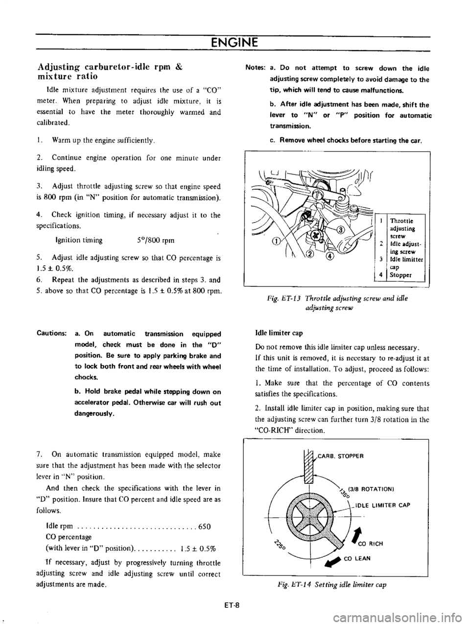
Throttle
adjusting
screw
Idle
adjust
ing
screw
3
Idle
limitter
cap
4
Stopper
Fig
ET
13
Throttle
adjusting
screw
and
idle
adjusting
screw
Idle
limiter
cap
Do
not
remove
this
idle
limiter
cap
unless
necessary
If
this
unit
is
removed
it
is
necessary
to
re
adjust
it
at
the
time
of
installation
To
adjust
proceed
as
follows
L
Make
sure
that
the
percentage
of
CO
contents
satisfies
the
specifications
2
Install
idle
limiter
cap
in
position
making
sure
that
the
adjusting
screw
can
further
turn
3
8
rotation
in
the
CO
RICH
direction
CARB
STOPPER
J
Z
3
8
ROTATION
0
IDLE
LIMITER
CAP
0
to
RICH
CO
LEAN
Fig
l
T
14
Setting
idle
limiter
cap
ET
8
Page 314 of 513

EMISSION
CONTROL
AND
TUNE
UP
Checking
and
adjusting
dash
pot
automatic
transmission
model
only
Check
operation
of
dash
pot
It
should
not
be
cracked
or
bound
It
is
also
essential
to
check
to
be
certain
that
it
is
in
correct
adjustment
L
Check
to
be
sure
that
dash
pot
contacts
stopper
lever
when
engine
speed
reaches
1
900
to
2
000
rpm
2
Engine
should
be
slowed
down
from
3
000
to
1
000
rpm
within
a
few
seconds
Readjust
dash
pot
or
replace
it
with
a
new
one
if
it
fails
to
meet
the
above
conditions
Checking
carburetor
return
spring
Check
throttle
return
spring
for
sign
of
damage
wear
or
squareness
Discard
spring
if
found
with
any
of
above
excessively
beyond
use
Checking
choke
mechanism
choke
valve
and
linkage
1
Check
choke
valve
and
mechanism
for
free
operation
and
clean
or
replace
if
necessary
A
binding
condition
may
have
developed
from
petro
leum
gum
for
motion
on
choke
shaft
or
from
damage
2
Check
bimetal
cover
setting
position
The
index
mark
of
bimetal
cover
is
usually
aligned
at
the
middle
point
of
the
scale
Note
When
somewhat
over
choked
turn
bimetal
caver
clockwise
slightly
3
Prior
to
starting
check
to
be
sure
that
choke
valve
closes
automatically
when
pressing
down
on
accelerator
pedal
Should
it
fail
to
close
automatically
the
likelihood
is
that
fast
idle
cam
is
out
of
proper
adjustment
or
that
bimetal
is
not
properly
adjusted
calling
for
adjustment
Refer
to
Carburetor
in
Section
EF
Page
EF
15
Checking
anti
dieseling
solenoid
If
engine
will
not
stop
when
ignition
switch
is
turned
off
this
indicates
a
striking
closed
solenoid
valve
shutting
off
supply
of
fuel
to
engine
If
harness
is
in
good
condition
replace
solenoid
as
a
unit
To
replace
proceed
as
follows
Removal
and
installation
of
anti
dieseling
solenoid
Removal
Solenoid
is
cemented
at
factory
Use
special
tool
STl
91
50000
to
remove
a
solenoid
When
this
tool
is
not
effective
use
a
pair
of
pliers
to
loosen
body
out
of
position
lnstalltion
I
Before
installing
a
solenoid
it
is
essential
to
clean
all
threaded
parts
of
carburetor
and
solenoid
Supply
screws
in
holes
and
turn
them
in
two
or
three
pitches
2
First
without
disturbing
the
above
setting
coat
all
exposed
threads
with
adhensive
the
Stud
Lock
of
LOCTlTE
or
equivalent
Then
torque
screws
to
35
to
55
kg
cm
30
to
48
in
lb
using
a
special
tool
STl9150000
After
installing
anti
dieseling
solenoid
leave
the
carbu
retor
more
than
12
hours
without
operation
3
After
replacement
is
over
start
engine
and
check
to
be
sure
that
fuel
is
not
leaking
and
that
anti
dieseling
solenoid
is
in
good
condition
Notes
a
Do
not
allow
adhesive
getting
on
valve
Failure
to
follow
this
caution
would
result
in
improper
valve
performance
or
clogged
fuel
passage
b
I
n
installing
valve
use
caution
not
to
hold
body
directly
Instead
use
special
tool
tighten
ing
nuts
as
required
ET
9
Page 319 of 513

ENGINE
Adjusting
throttle
opener
setting
engine
speed
1
Connect
servo
diaphragm
vacuum
hose
directly
to
intake
manifold
connector
without
laying
through
vacuum
control
valve
2
With
negative
pressure
vacuum
in
intake
manifold
servo
diaphragm
operates
and
thus
the
primary
throttle
valve
is
opened
When
servo
diaphragm
nor
mally
operates
engine
speed
rises
reaching
1
650
to
1
850
rpm
When
engine
speed
is
not
within
this
range
turn
adjusting
screw
as
necessary
See
Figure
ET
20
l
When
engine
speed
is
lower
than
the
prescribed
range
turn
adjusting
screw
clockwise
2
When
engine
speed
is
higher
than
the
prescribed
range
turn
adjusting
screw
counterclockwise
Upon
completion
of
the
adjustment
set
adjusting
screw
lock
nut
secwely
making
sure
that
engine
speed
is
in
the
prescribed
range
@
II
I
AdJustmg
screw
2
Lock
nut
Fig
ET
20
Servo
diaphragm
adjusting
screw
Servo
diaphragm
Servo
diaphragm
stroke
Link
EC015
3
Disconnect
servo
diaphragm
vacuum
hose
from
intake
manifold
and
connect
it
to
vacuum
control
valve
Connect
vacuum
hose
of
control
valve
to
intake
manifold
normal
piping
Racing
Place
shift
lever
in
neutral
for
MfT
or
N
or
p
for
AlT
Raise
engine
speed
up
to
approximately
3
000
rpm
under
no
load
and
close
throttle
valve
by
releasing
it
from
hand
Examine
engine
speed
to
see
whether
it
falls
to
idling
speed
I
When
engine
revolution
rails
to
idling
speed
See
Figure
ET
24
The
primary
throttle
valve
is
opened
by
the
link
connected
to
it
When
the
engine
speed
is
increased
to
approximately
3
000
rpm
and
lowered
natually
from
this
speed
changes
in
servo
diaphragm
link
stroke
manifold
vacuum
and
en
ine
speed
are
as
shown
in
Figure
ET
21
o
u
u
0
2
Se
o
diaphragm
link
stroke
I
u
2
Full
0
o
Intake
manifold
vacuum
u
c
E
c
O
3000
c
e
Engine
speed
2000
g
i
c
1000
T
j
Time
second
Fig
ET
21
Changes
in
servo
diaphragm
link
stroke
intake
manifold
vacuum
and
engine
speed
ET
14
Page 321 of 513
ENGINE
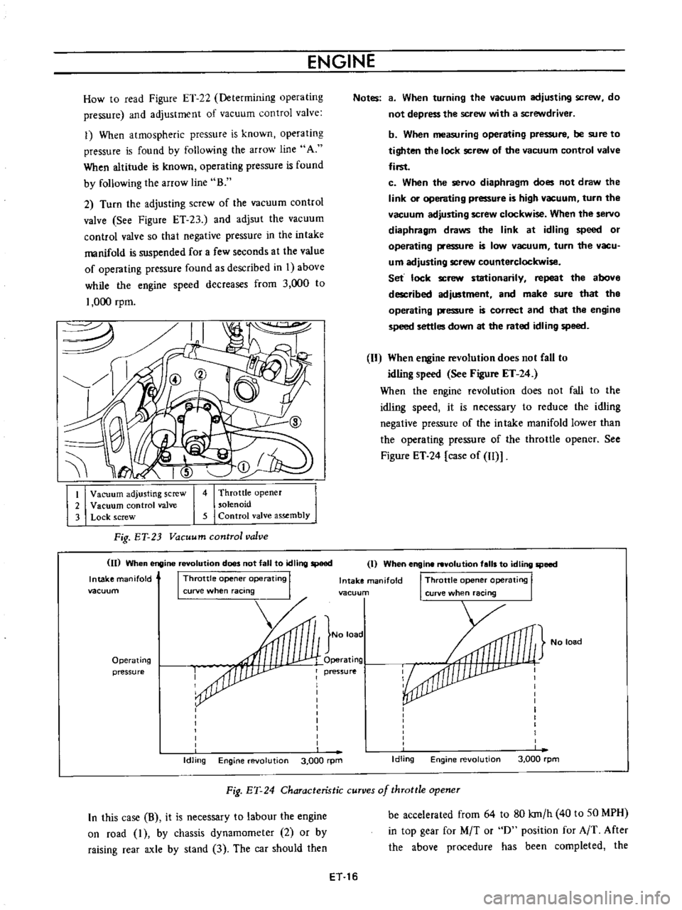
How
to
read
Figure
ET
22
Determining
operating
pressure
and
adjustment
of
vacuum
control
valve
1
When
atmospheric
pressure
is
known
operating
pressure
is
found
by
following
the
arrow
line
A
When
altitude
is
known
operating
pressure
is
found
by
following
the
arroW
line
B
2
Turn
the
adjusting
screw
of
the
vacuum
control
valve
See
Figure
ET
23
and
adjsut
the
vacuum
control
valve
so
that
negative
pressure
in
the
intake
manifold
is
suspended
for
a
few
seconds
at
the
value
of
operating
pressure
found
as
described
in
I
above
while
the
engine
speed
decreases
from
3
000
to
1
000
rpm
I
Vacuum
adjusting
screw
2
Vacuum
control
valve
3
Lock
screw
4
Throttle
opener
solenoid
5
Control
valve
assembly
Fig
ET
23
Vacuum
control
valve
II
When
engine
revolution
does
not
fall
to
tdling
speed
Intake
manifold
I
Throttle
opene
operating
I
vacuum
curve
when
racing
Operating
pressure
Idling
Engine
evolution
3
000
rpm
Notes
a
When
turning
the
vacuum
adjusting
scre
N
do
not
depress
the
screw
with
a
screwdriver
b
When
measuring
operating
pressure
be
sure
to
tighten
the
lock
screw
of
the
vacuum
control
valve
first
c
When
the
servo
diaphragm
does
not
draw
the
link
or
operating
pressure
is
high
vacuum
turn
the
vacuum
adjusting
screw
clockwise
When
the
servo
diaphragm
draws
the
link
at
idling
speed
or
operating
pressure
is
low
vacuum
turn
the
vacu
um
adjusting
screw
counterclockwise
Set
lock
screw
stationarily
repeat
the
above
described
adjustment
and
make
sure
that
tho
operating
pressure
is
correct
and
that
the
engine
speed
settles
down
at
the
rated
idling
speed
When
engine
revolution
does
not
CaU
to
idling
speed
See
Figure
ET
24
When
the
engine
revolution
does
not
fall
to
the
idling
speed
it
is
necessary
to
reduce
the
idling
negative
pressure
of
the
intake
manifold
lower
than
the
operating
pressure
of
the
throttle
opener
See
Figure
ET
24
case
of
Il
Il
I
When
engine
revolution
falls
to
idling
speed
Intake
manifold
I
Throttle
opene
operating
I
vacuun
curve
when
racing
No
load
No
load
Operating
pressure
I
I
I
I
I
I
I
I
I
Idling
Engine
revolution
3
000
rpm
Fig
EY
24
Characteristic
curves
of
throttle
opener
In
this
case
B
it
is
necessary
to
labour
the
engine
on
road
I
by
chassis
dynamometer
2
or
by
raising
rear
axle
by
stand
3
The
car
should
then
be
accelerated
from
64
to
80
kro
h
40
to
SO
MPH
in
top
gear
for
M
T
or
0
position
for
A
T
After
the
above
procedure
has
been
completed
the
ET
16
Page 322 of 513
EMISSION
CONTROL
AND
TUNE
UP
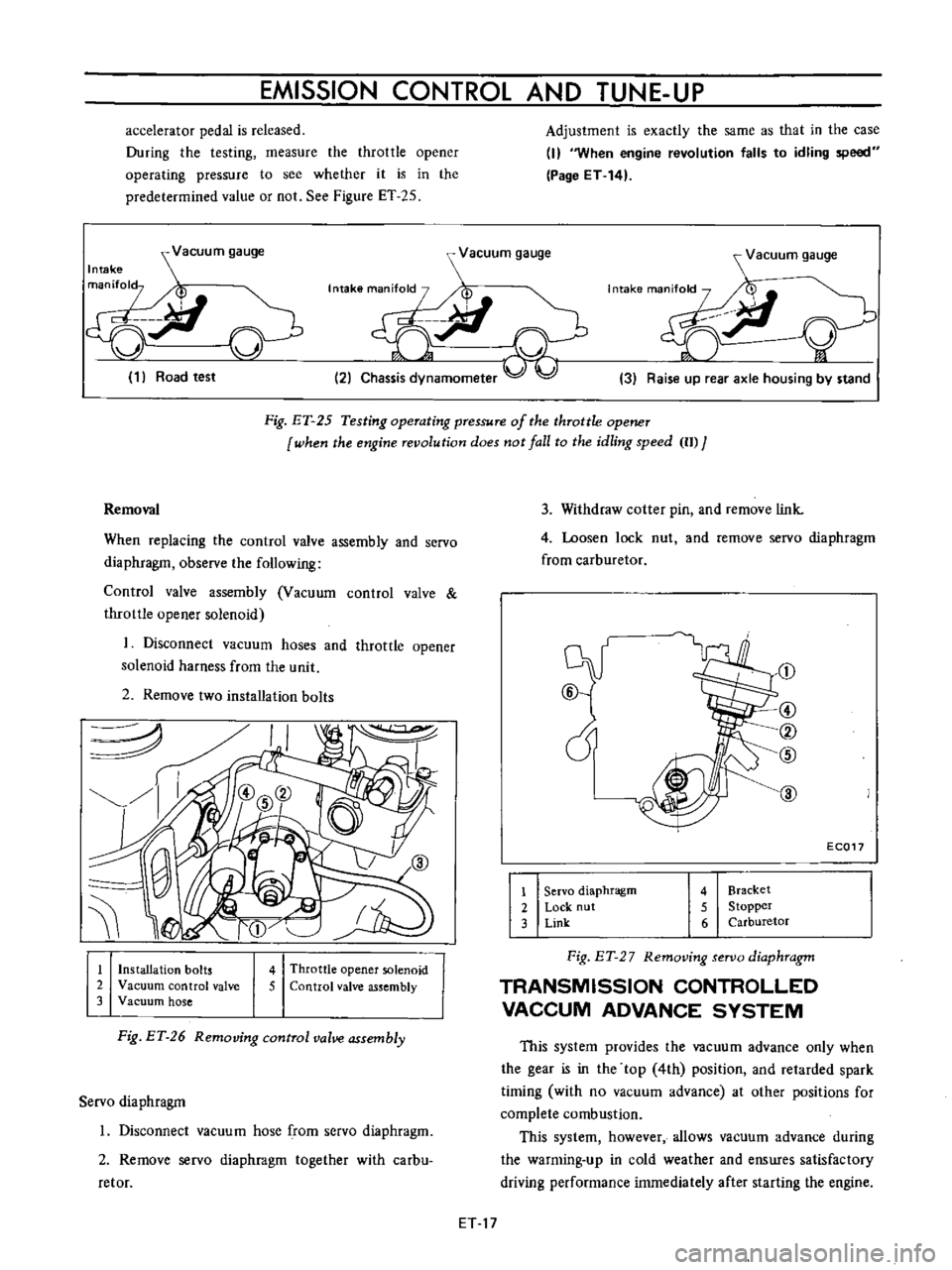
accelerator
pedal
is
released
During
the
testing
measure
the
throttle
opener
operating
pressure
to
see
whether
it
is
in
the
predetermined
value
or
not
See
Figure
ET
25
Adjustment
is
exactly
the
same
as
that
in
the
case
I
When
engine
revolution
falls
to
idling
speed
Page
ET
14
Vacuum
gauge
Intake
man
fol
p
ci
J
v
1
Road
test
r
Vacuum
gauge
7I
t
i
2
Chassis
dynamometer
Vacuum
gauge
y
3
Raise
up
rear
axle
housing
by
stand
Fig
ET
25
Testing
operating
pressure
of
the
throttle
opener
when
fhe
engine
revolufion
does
not
lall
fo
fhe
idling
speed
II
J
3
Withdraw
cotter
pin
and
remove
link
4
Loosen
lock
nut
and
remove
servo
diaphragm
from
carburetor
Removal
When
replacing
the
control
valve
assembly
and
servo
diaphragm
observe
the
following
Control
valve
assembly
Vacuum
control
valve
throttle
opener
solenoid
1
Disconnect
vacuum
hoses
and
throttle
opener
solenoid
harness
from
the
unit
2
Remove
two
installation
bolts
J
@
cY
@
1
Servo
diaphragm
2
Lock
nut
3
Link
@
CV
@
EC017
4
Bracket
5
Stopper
6
Carburetor
1
Installation
bolts
2
Vacuum
control
valve
3
Vacuum
hose
4
Throttle
opener
solenoid
5
Control
valve
assembly
Fig
ET
2
7
Removing
servo
diaphragm
TRANSMISSION
CONTROLLED
VACCUM
ADVANCE
SYSTEM
Fig
ET
26
Removing
control
valve
assembly
This
system
provides
the
vacuum
advance
only
when
the
gear
is
in
the
top
4th
position
and
retarded
spark
timing
with
no
vacuum
advance
at
other
positions
for
complete
combustion
This
system
however
allows
vacuum
advance
during
the
warming
up
in
cold
weather
and
enswes
satisfactory
driving
performance
immediately
after
starting
the
engine
Servo
diaphragm
1
Disconnect
vacuum
hose
from
servo
diaphragm
2
Remove
servo
diaphragm
together
with
carbu
retor
ET
17
Page 325 of 513
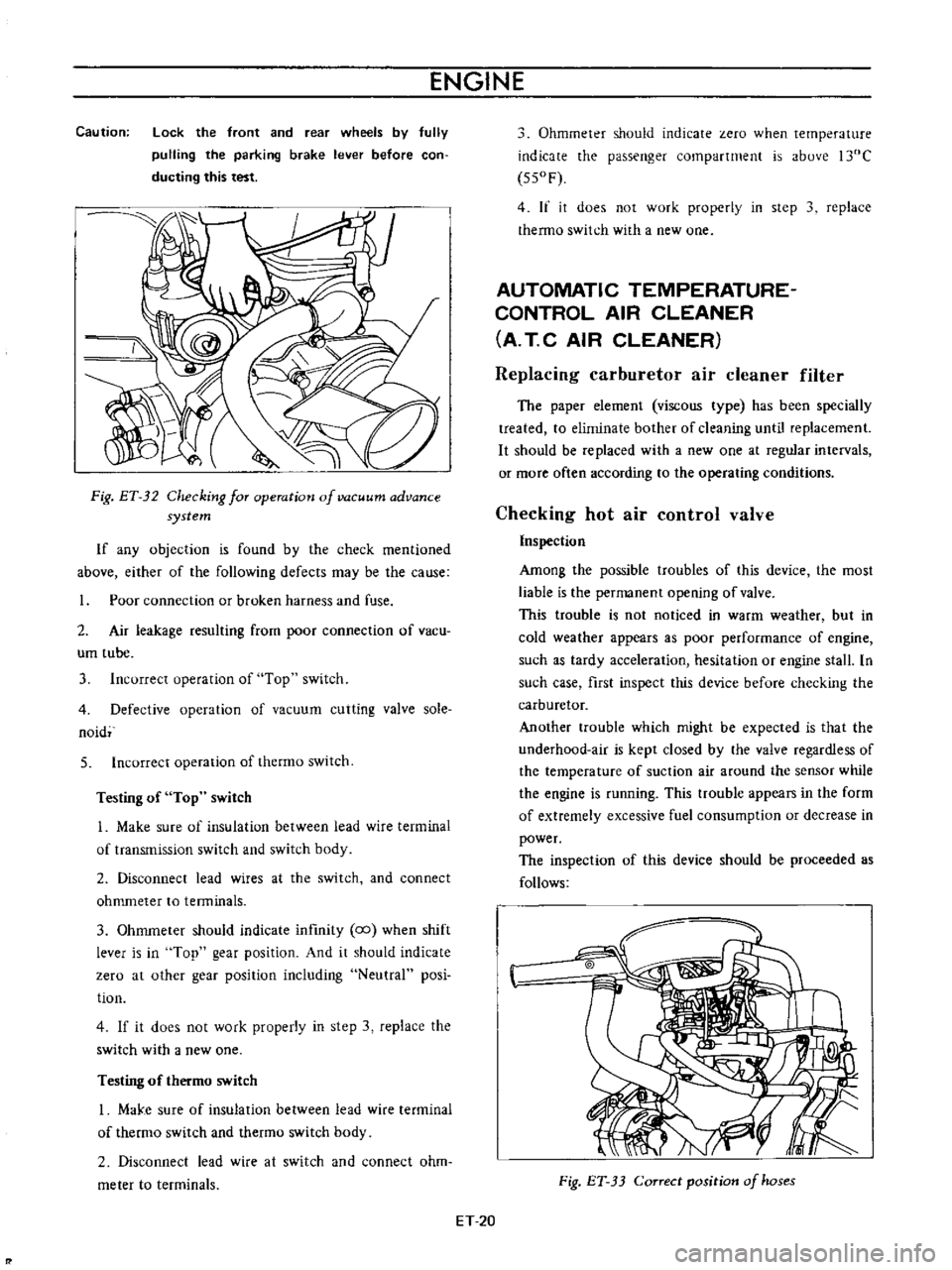
ENGINE
Caution
lock
the
front
and
rear
wheels
by
fully
pulling
the
parking
brake
lever
before
con
ducting
this
test
Fig
ET
32
Checking
for
operation
of
vacuum
advance
system
If
any
objection
is
found
by
the
check
mentioned
above
either
of
the
following
defects
may
be
the
cause
Poor
connection
or
broken
harness
and
fuse
2
Air
leakage
resulting
from
poor
connection
of
vacu
um
tube
3
Incorrect
operation
of
Top
switch
4
Defective
operation
of
vacuum
cutting
valve
sole
naid
5
Incorrect
operation
of
thermo
switch
Testing
of
Top
switch
1
Make
sure
of
insulation
between
lead
wire
terminal
of
transmission
switch
and
switch
body
2
Disconnect
lead
wires
at
the
switch
and
connect
ohmmeter
to
tenninals
3
Ohmmeter
should
indicate
infmity
co
when
shift
lever
is
in
Top
gear
position
And
it
should
indicate
zero
at
other
gear
position
including
Neutral
posi
tion
4
If
it
does
not
work
properly
in
step
3
replace
the
switch
with
a
new
one
Testing
of
thermo
switch
I
MaJ
e
sure
of
insulation
between
lead
wire
terminal
of
thermo
switch
and
thetmo
switch
body
2
Disconnect
lead
wire
at
switch
and
connect
ohm
meter
to
terminals
Ohmmeter
should
indicate
zero
when
temperature
indicate
the
passenger
compartment
is
above
l30C
550F
4
If
it
does
not
work
properly
in
step
3
replace
thermo
switch
with
a
new
one
AUTOMATIC
TEMPERATURE
CONTROL
AIR
CLEANER
A
T
C
AIR
CLEANER
Replacing
carburetor
air
cleaner
filter
The
paper
element
viscous
type
has
been
specially
treated
to
eliminate
bother
of
cleaning
until
replacement
It
should
be
replaced
with
a
new
one
at
regular
intervals
or
more
often
according
to
the
operating
conditions
Checking
hot
air
control
valve
Inspection
Among
the
possible
troubles
of
this
device
the
most
liable
is
the
permanent
opening
of
valve
This
trouble
is
not
noticed
in
warm
weather
but
in
cold
weather
appears
as
poor
performance
of
engine
such
as
tardy
acceleration
hesitation
or
engine
stall
In
such
case
first
inspect
this
device
before
checking
the
carburetor
Another
trouble
which
might
be
expected
is
that
the
underhood
air
is
kept
closed
by
the
valve
regardless
of
the
temperature
of
suction
air
around
the
sensor
while
the
engine
is
running
This
ttOuble
appears
in
the
form
of
extremely
excessive
fuel
consumption
or
decrease
in
power
The
inspection
of
this
device
should
be
proceeded
as
follows
Fig
ET
33
Correct
position
of
hoses
ET
20