1973 DATSUN B110 lock
[x] Cancel search: lockPage 235 of 513
DATSUN
1200
MODEL
B
11
0
SERIES
I
NISSAN
I
NISSAN
MOTOR
CO
LTD
TOKYO
JAPAN
SECTION
BE
BODY
ELECTRICAL
WIRING
FUSE
LIGHTING
SYSTEM
HORN
METERS
AND
GAUGES
WINDSHIELD
WIPER
AND
WASHER
IGNITION
SWITCH
AND
STEERING
LOCK
CLOCK
RADIO
HEATER
BE
1
BE
6
BE
7
BE
15
BE
18
BE
26
BE
29
BE
31
BE
32
BE
34
Page 243 of 513
n
YR
f
f1
JC
1
r
8bD
l
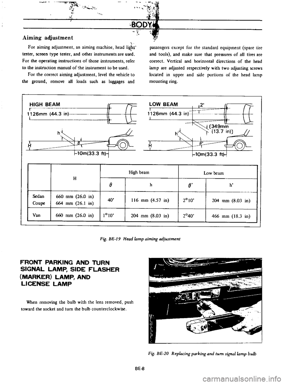
Aiming
adjustment
For
aiming
adjustment
an
aiming
machine
head
i
l
tester
screen
type
tester
and
other
instruments
are
used
For
the
operating
instructions
of
those
instruments
refer
to
the
instruction
manual
of
the
instrument
to
be
used
For
the
correct
airning
adjustment
level
the
vehicle
to
the
ground
remove
all
loads
such
as
luggages
and
HIGH
BEAM
I
1126mm
44
3
in
I
it
E
U
o
h
H
I
10m
33
3
ft
1
r
passengers
except
for
the
standard
equipment
spare
tire
and
tools
and
make
sure
that
pressures
of
all
tires
are
correct
Vertical
and
horizontal
directions
of
the
head
lamp
are
adjusted
respectively
with
two
adjusting
screws
located
in
upper
and
side
portions
of
the
head
lamp
mounting
ring
lOW
BEAM
12
I
f
tt
1126mm
44
3
in
I
l
349mm
h
t
13
7
in
10m
33
3
ft
I
H
I
High
beam
Low
beam
H
j
h
j
h
Sedan
660
mm
26
0
in
2010
Coupe
664
mm
26
1
in
40
116
mm
4
57
in
204
mm
8
03
in
Van
660
mm
26
0
in
1010
204
mm
8
03
in
2040
466
mm
18
3
in
Fig
BE
19
Head
lamp
aiming
adjustment
FRONT
PARKING
AND
TURN
SIGNAL
LAMP
SIDE
FLASHER
MARKER
LAMP
AND
LICENSE
LAMP
When
removing
the
bulb
with
the
lens
removed
push
toward
the
socket
and
turn
the
bulb
counterclockwise
Fig
BE
20
Replacing
parking
and
turn
signa
lamp
bulb
BE
8
Page 244 of 513
r
BODY
ELECTRICAL
Fig
BE
21
Replacing
side
lasher
lamp
bulb
Fig
BE
22
Replacing
license
lamp
bulb
REAR
COMBINATION
LAMPS
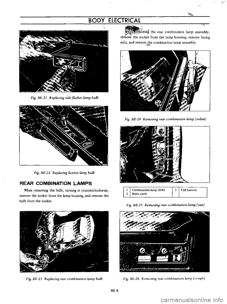
When
removing
the
bulb
turning
it
counterclockwise
remove
the
socket
from
the
lamp
housing
and
rernove
the
bulb
from
the
socket
Fig
BE
23
Replacing
rear
combination
lamp
bulb
r
oving
the
rear
combination
lamp
assembly
remove
the
socket
from
the
lamp
housing
remove
fixing
nuts
and
remove
the
combination
lamp
assembly
1
0
Fig
BE
24
Removing
rear
combination
lamp
sedan
1
I
Combination
lamp
RH
2
Body
earth
I
J
I
Tail
harness
Fig
BE
25
Removing
Tear
combination
lamp
van
Fig
BE
26
Remavinit
r
ar
combirwtioH
lamI
coupe
BE
9
Page 246 of 513

BODY
ELECTRICAL
8
G
J
r
ICENSE
LAMPS
10
0
I
I
g
N
Ap
KING
10
00
01
2
I
NATION
J
J
r
j
a
iii
a
g
Lv
F
a
G
G
Lo
o
0
I
I
m
L
J
HER
UNIT
DIMMER
SWITCH
TURN
SIONAl
SWITCH
I
I
Fig
BE
28
Circuit
diagram
for
turn
signal
and
dimmer
switch
system
LIGHTING
SWITCH
HAZARD
WARNING
SWITCH
Removal
The
hazard
lamp
system
4
way
flasher
consists
of
hazard
warning
switch
and
flasher
unit
When
the
hazard
warning
switch
is
turned
on
all
signal
lamps
flash
simultaneously
telling
other
drivers
that
the
vehicle
is
stopped
When
the
turn
signal
lamps
flash
the
pilot
lamps
on
the
instrument
panel
also
flash
telling
you
of
hazard
lamp
operation
1
Rernove
the
connector
from
back
of
the
lighting
switch
2
Depressing
the
lighting
switch
knob
turn
it
counter
clockwise
and
remove
it
3
Loosen
the
escutcheon
switch
frorn
the
cluster
lid
and
remove
the
lighting
IGNITION
SWITCH
EZ
L
I
U
I
JJ
u
HAZARD
UNIT
Ip
FLASHER
UNIT
HAZARD
WARNING
SWITCH
161
6
6
g
Q
a
ll
Zll
Zll
CE
O
a
We
a
l
e
rY
1
LEFT
SiDE
RIGHT
SIDE
Fig
BE
29
Circuit
diagram
for
hazard
lamp
system
BE
11
Page 247 of 513
BODY
PASSING
LIGHT
SWITCH
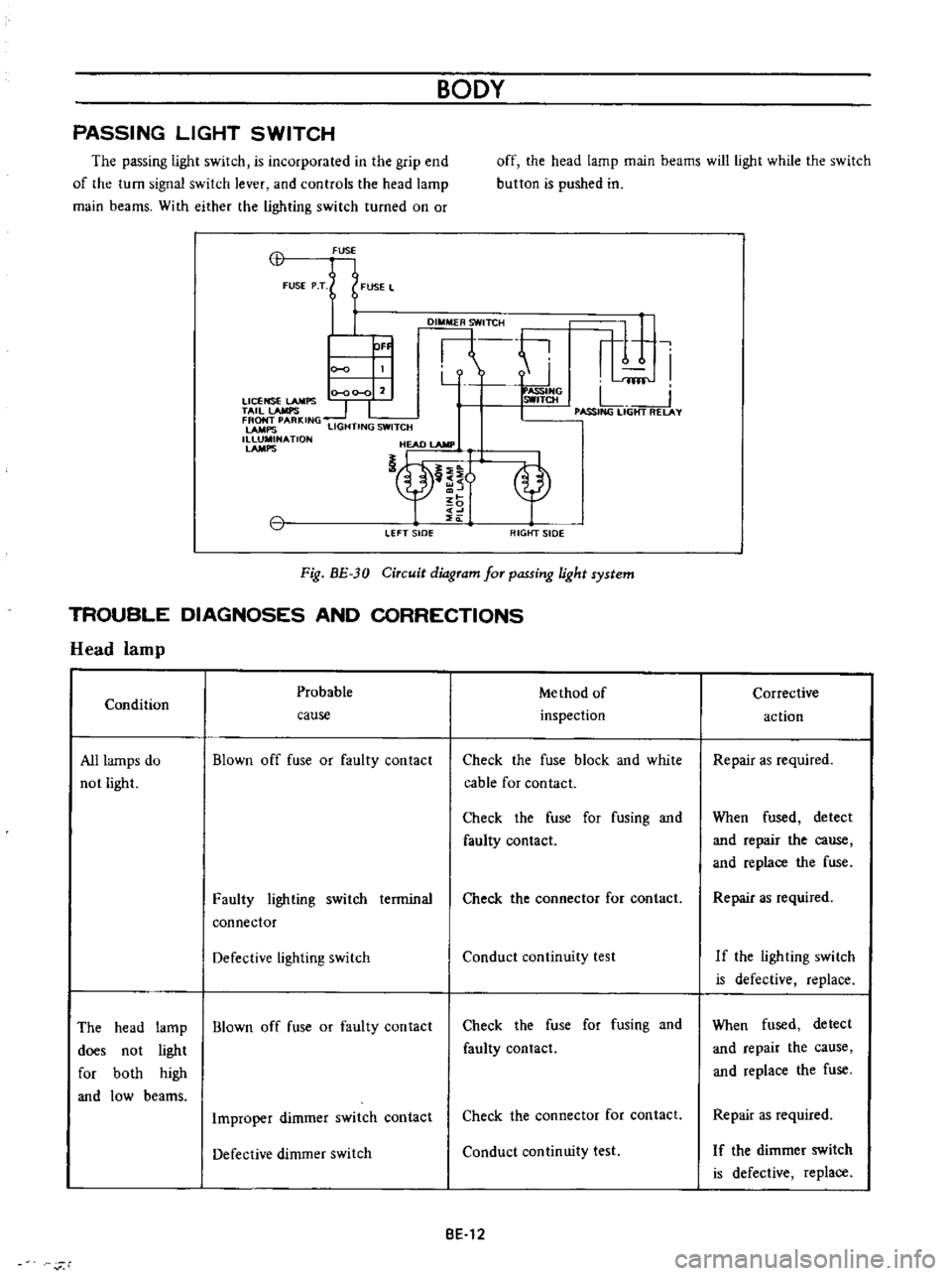
The
passing
light
switch
is
incorporated
in
the
grip
end
of
the
turn
signal
switch
lever
and
controls
the
head
lamp
main
beams
With
either
the
lighting
switch
turned
on
or
off
the
head
lamp
main
beams
will
light
while
the
switch
button
is
pushed
in
CB
FUSE
FUSE
P
T
FUSE
L
DI
TCH
ti
r
1
I
Y
fflf
0
00
0
2
ASSIHG
LICENSE
LAMPS
SWITCH
L
TAil
lAMPS
1
I
I
PASSING
LIGHT
RELAY
FRONT
PARKING
LAMPS
LIGHTING
SWITCH
1
NATlON
HEAD
lAMP
nt
OF
LEFT
sIDe
RIGtfT
SIDE
Fig
BE
30
Circuit
diagram
for
passing
light
system
TROUBLE
DIAGNOSES
AND
CORRECTIONS
Head
lamp
Probable
Me
thod
of
Condition
inspection
cause
All
lamps
do
not
light
Blown
off
fuse
or
faulty
contact
Check
the
fuse
block
and
white
cable
for
contact
Check
the
fuse
for
fusing
and
faulty
contact
Faulty
lighting
switch
terminal
connector
Check
the
connector
for
contact
Defective
lighting
switch
Conduct
continuity
test
The
head
lamp
Blown
off
fuse
or
faulty
contact
does
not
light
for
both
high
and
low
beams
Check
the
fuse
for
fusing
and
faulty
contact
Improper
dimmer
switch
contact
Check
the
connector
for
contact
Defective
dimmer
switch
Conduct
continuity
test
BE
12
r
Corrective
action
Repair
as
required
When
fused
detect
and
repair
the
cause
and
replace
the
fuse
Repair
as
required
If
the
ligh
ting
swi
tch
is
defective
replace
When
fused
detect
and
repair
the
cause
and
replace
the
fuse
Repair
as
required
I
f
the
dimmer
switch
is
defective
replace
Page 251 of 513
9HORN
r
I
01
8ATTERY
HI
IGI
s
ILl
C
iORN
BODY
FUSE
H
S
HORN
BUTTON
BGI
J
H
B
S
Il
I
n6lm
I
L
J
L
HORN
RELAY
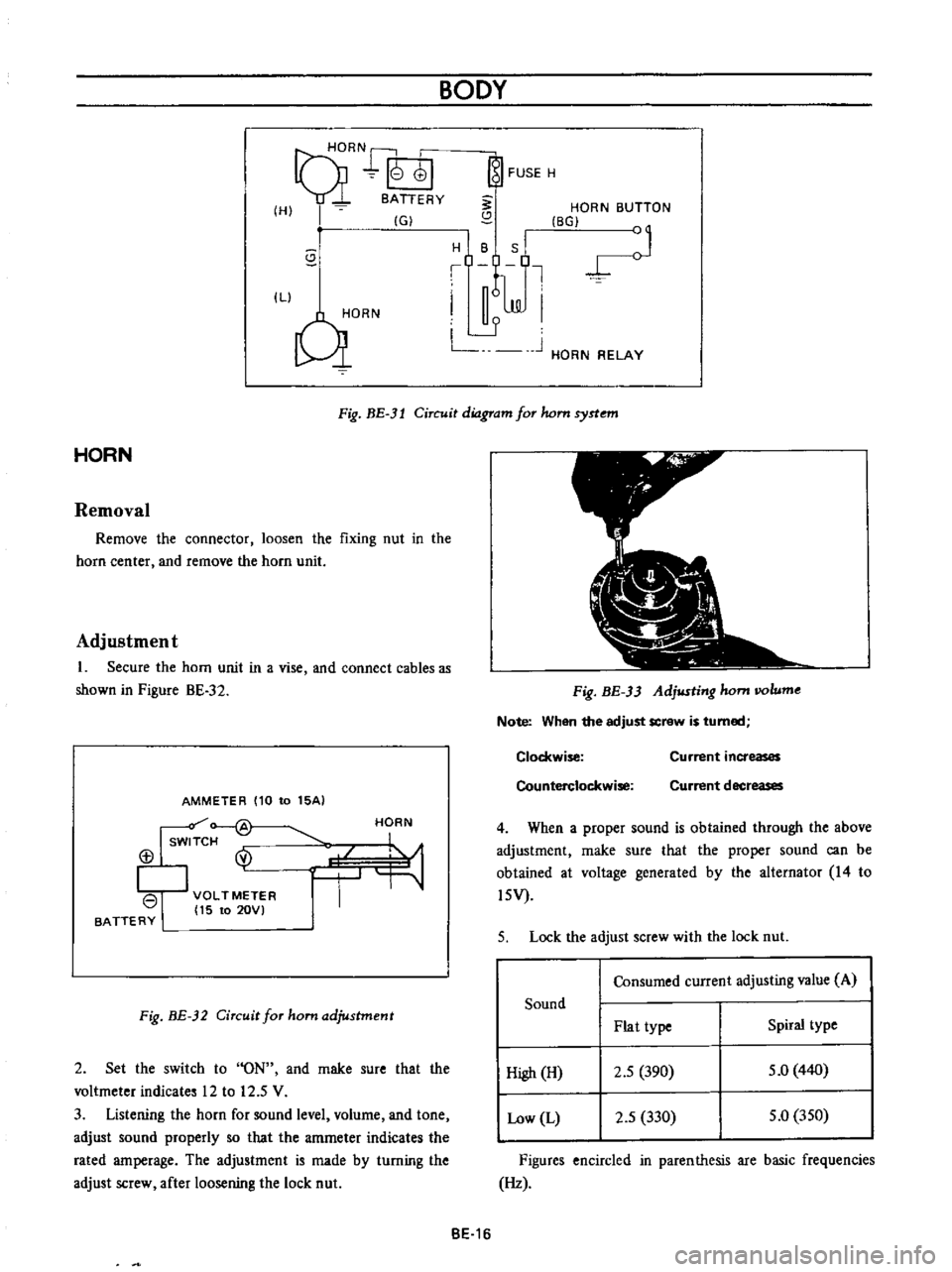
Fig
BE
3l
Circuit
diagram
for
hom
syrtem
HORN
Removal
Remove
the
connector
loosen
the
fixing
nut
in
the
horn
center
and
remove
the
horn
unit
Adjustment
1
Secure
the
horn
unit
in
a
vise
and
connect
cables
as
shown
in
Pigure
BE
32
AMMETER
110
to
15AI
Isw
f
@
113
I
VOLTMETER
I
15
to
20VI
BATTERY
HORN
Fig
BE
32
Circuit
for
ham
adjustment
2
Set
the
switch
to
ON
and
rnake
sure
that
the
voltmeter
indicates
12
to
12
5
V
3
Listening
the
horn
for
sound
level
volurne
and
tone
adjust
sound
properly
so
that
the
amrneter
indicates
the
rated
amperage
The
adjustment
is
made
by
turning
the
adjust
screw
after
loosening
the
lock
nut
Fig
BE
33
Adjusting
hom
IIOlume
Note
When
the
adjust
screw
is
turned
Clockwise
Counterclockwise
Current
increases
Current
decreases
4
When
a
proper
sound
is
obtained
through
the
above
adjustment
rnake
sure
that
the
proper
sound
can
be
obtained
at
voltage
generated
by
the
alternator
14
to
l5V
5
Lock
the
adjust
screw
with
the
lock
nut
Consumed
current
adjusting
value
A
Sound
Plat
type
Spiral
type
High
H
2
5
390
5
0
440
Low
L
2
5
330
5
0
350
Figures
encircled
in
parenthesis
are
basic
frequencies
Hz
BE
16
Page 253 of 513

BODY
METERS
AND
GAUGES
CONTENTS
CLUSTER
LID
Oescri
ption
Removal
SPEEDOMETER
Replacement
FUEL
GAUGE
AND
TEMPERATURE
GAUGE
Description
Replacement
BE
1B
BE
18
BE
18
BE
19
BE
19
BE
19
BE
19
BE
20
CLUSTER
LID
Description
The
cluster
lid
holds
various
rneters
indicators
and
clock
located
around
the
speedorneter
Printed
circuit
board
is
used
at
the
back
of
the
meter
as
shown
in
Figure
BE
38
and
the
printed
circuit
board
is
connected
with
multiple
connectors
Thus
the
meters
Can
be
inspected
and
serviced
extremely
easily
Except
for
the
speed
ometer
all
rneters
are
operated
electrically
The
fuel
gauge
and
therrnometer
are
very
reliable
and
they
are
equipped
with
bimetal
devices
F
a
o
ill
I
1
a
a
Fig
BE
34
Combination
meters
Removal
Disconnect
the
battery
terminal
depressing
the
OIL
PRESSURE
AND
IGNITION
WARNING
LAMPS
HAND
BRAKE
WARNING
LAMP
BULB
SPECIFICATIONS
TROUBLE
DIAGNOSES
AND
CORRECTIONS
Speedometer
Thermometer
and
fuel
meter
Oil
pressure
and
ignition
warning
lamps
BE
20
BE
21
BE
21
BE
22
BE
22
BE
23
BE
25
windshield
wiper
switch
lighting
switch
and
choke
lever
knobs
turn
them
counterclockwise
to
remove
Remove
the
escutcheon
2
Inserting
your
hand
into
back
of
the
cluster
lid
disconnect
the
cigarette
lighter
cable
and
turn
and
remove
the
cigarette
lighter
outer
case
3
Remove
the
radio
and
heater
control
knobs
4
Remove
the
shell
cover
from
the
steering
tube
loosen
the
screws
used
to
secure
the
meter
housing
to
the
instrument
panel
and
remove
the
cluster
lid
5
Pull
out
the
l2
pole
round
shape
connector
and
remove
the
speedometer
cable
union
nut
6
Remove
the
cluster
lid
from
the
instrument
panel
Fig
BE
35
Removing
clllSter
jd
BE
18
Page 254 of 513
BODY
ELECTRICAL
SPEEDOMETER
The
speedometer
is
equipped
with
a
total
odometer
which
records
travelled
distance
Replacement
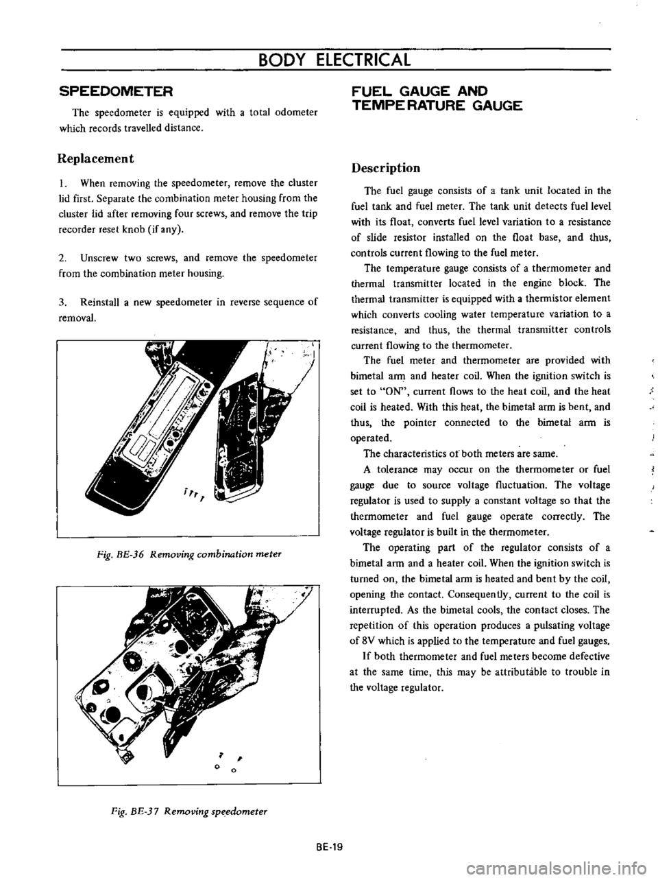
1
When
removing
the
speedometer
remove
the
cluster
lid
first
Separate
the
combination
meter
housing
from
the
cluster
lid
after
removing
four
screws
and
remove
the
trip
recorder
reset
knob
if
any
2
Unscrew
two
screws
and
remove
the
speedometer
from
the
combination
meter
housing
3
Reinstall
a
new
speedometer
in
reverse
sequence
of
removal
Fig
BE
36
Removing
combination
meter
o
Fig
BE
37
Removing
sp
edometer
FUEL
GAUGE
AND
TEMPE
RATURE
GAUGE
Description
The
fuel
gauge
consists
of
a
tank
unit
located
in
the
fuel
tank
and
fuel
meter
The
tank
unit
detects
fuel
level
with
its
float
converts
fuel
level
variation
to
a
resistance
of
slide
resistor
installed
on
the
float
base
and
thus
controls
current
flowing
to
the
fuel
meter
The
temperature
gauge
consists
of
a
thermorneter
and
thermal
transmitter
located
in
the
engine
block
The
thermal
transmitter
is
equipped
with
a
thermistor
element
which
converts
cooling
water
temperature
variation
to
a
resistance
and
thus
the
thermal
transmitter
controls
current
flowing
to
the
thermometer
The
fuel
rneter
and
thermometer
are
provided
with
bimetal
a
and
heater
coil
When
the
ignition
switch
is
set
to
ON
current
flows
to
the
heat
coil
and
the
heat
coil
is
heated
With
this
heat
the
bimetal
arm
is
bent
and
thus
the
pointer
connected
to
the
bimetal
ann
is
operated
The
characteristics
ot
both
meters
are
same
A
tolerance
may
occur
on
the
thermometer
or
fuel
gauge
due
to
source
voltage
fluctuation
The
voltage
regulator
is
used
to
supply
a
constant
voltage
so
that
the
therrnorneter
and
fuel
gauge
operate
correctly
The
voltage
regulator
is
built
in
the
thermometer
The
operating
part
of
the
regulator
consists
of
a
bimetal
arm
and
a
heater
coil
When
the
ignition
switch
is
turned
on
the
birnetal
arm
is
heated
and
bent
by
the
coil
opening
the
contact
Consequently
current
to
the
coil
is
interrupted
As
the
bimetal
cools
the
contact
closes
The
repetition
of
this
operation
produces
a
pulsating
voltage
of
8V
which
is
applied
to
the
ternperature
and
fuel
gauges
If
both
thermometer
and
fuel
meters
become
defective
at
the
same
time
this
may
be
attributable
to
trouble
in
the
voltage
regulator
BE
19