1973 DATSUN B110 lock
[x] Cancel search: lockPage 142 of 513
CHASSIS
Reassembly
and
reinstallation
Reassemble
and
reinstall
the
rear
brake
in
reverse
sequence
of
disassembly
and
removal
nuting
the
follow
ing
matters
When
reassembling
refer
to
the
notes
for
front
drum
brake
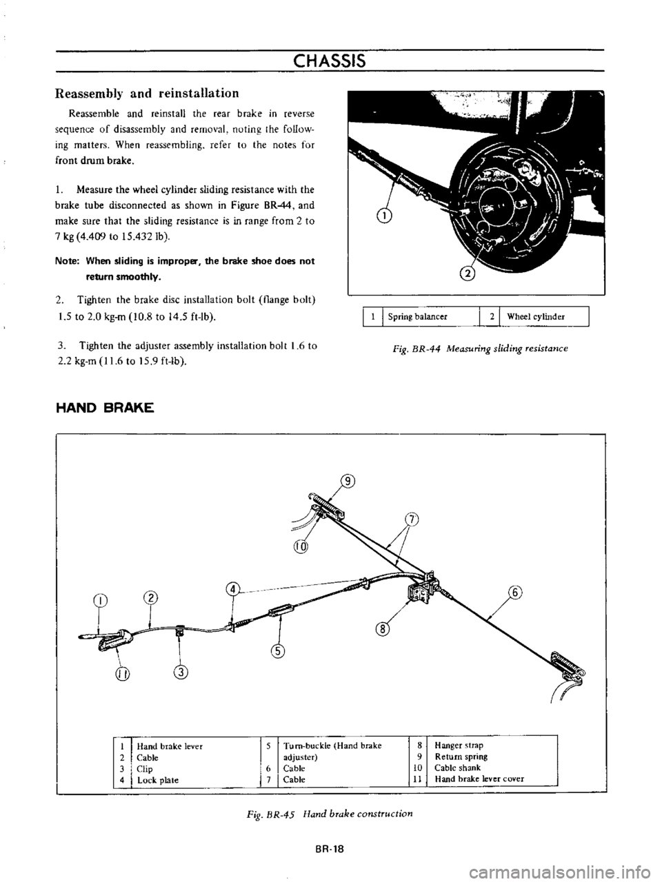
1
Measure
the
wheel
cylinder
sliding
resistance
with
the
brake
tube
disconnected
as
shown
in
Figure
BRM
and
make
sure
that
the
sliding
resistance
is
in
range
from
2
to
7
kg
4
409
to
15
432Ib
Note
When
sliding
is
improper
the
brake
shoe
does
not
return
smoothly
2
Tighten
the
brake
disc
installation
bolt
flange
bolt
1
5
to
2
0
kg
m
10
8
to
14
5
ft
lb
3
Tighten
the
adjuster
assembly
installation
bolt
1
6
to
2
2
kg
m
11
6
to
15
9
ft
lb
HAND
BRAKE
4
j
1
I
1
I
Spring
balancer
I
2
I
Wheel
cylinder
Fig
BR
44
Measuring
sliding
resistance
1
Hand
brak
e
lever
2
Cable
3
Clip
4
Lock
plate
5
Tu
m
buckle
Hand
brake
adjuster
6
Cable
7
Cable
8
Hanger
strap
9
Return
spring
10
Cable
shank
11
Hand
brake
lever
cover
Fig
BR
45
Hand
brake
construction
BR
1B
Page 143 of 513
Removal
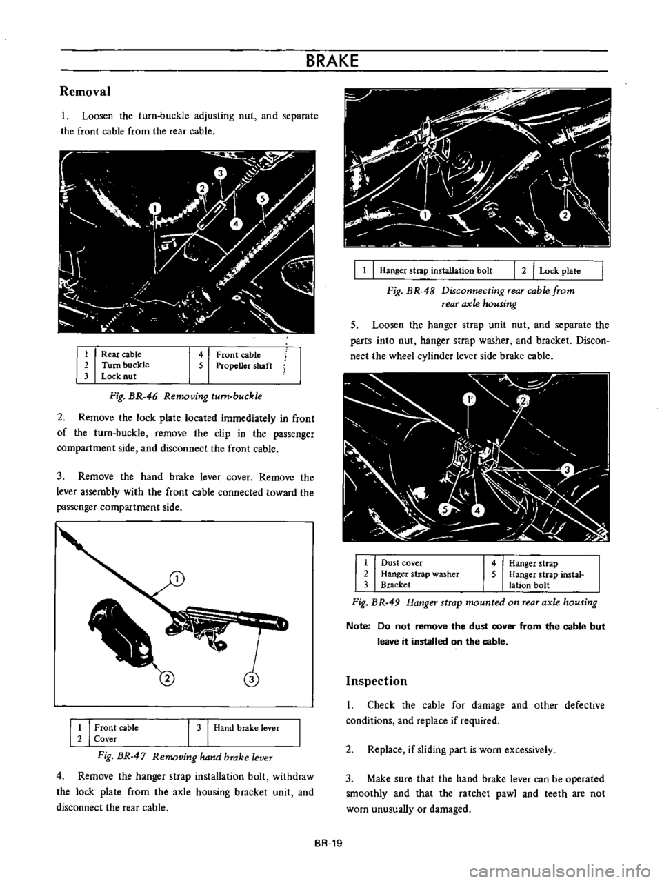
Loosen
the
turn
buckle
adjusting
nut
and
separate
the
front
cable
from
the
rear
cable
1
Rear
cable
2
Turn
buckle
3
Lock
nut
4
Front
cable
5
Propeller
shaft
Fig
BR
46
Removing
turn
buckle
2
Remove
the
lock
plate
located
immediately
in
front
of
the
turn
buckle
remove
the
clip
in
the
passenger
compartment
side
and
disconnect
the
front
cable
3
Remove
the
hand
brake
lever
cover
Remove
the
lever
assembly
with
the
front
cable
connected
toward
the
passenger
compartment
side
1
I
Front
cable
2
Cover
I
3
Hand
brake
lever
Fig
BR
47
Removing
hand
brake
lever
4
Remove
the
hanger
strap
installation
bolt
withdraw
the
lock
plate
from
the
axle
housing
brncket
unit
and
disconnect
the
rear
cable
BRAKE
I
1
I
Hanger
strap
installation
bolt
r
2
I
Lock
plate
Fig
BR
48
Disconnecting
Tear
cable
from
rear
axle
housing
5
Loosen
the
hanger
slrap
unit
nut
and
separate
the
parts
into
nut
hanger
strap
washer
and
bracket
Discon
nect
the
wheel
cylinder
lever
side
brake
cable
r
v
I
j
1
r
1fil
lt
J
l
1
1
I
c
2
1
Dust
cover
2
Hanger
strap
washer
3
Bracket
4
Hanger
strap
5
Hanger
strap
instal
lation
bolt
Fig
BR
49
Hanger
strap
mounted
on
rear
axle
housing
Note
Do
not
remove
the
dust
cover
from
the
cable
but
leave
it
installed
on
the
cable
Inspection
Check
the
cable
for
damage
and
other
defective
conditions
and
replace
if
required
2
Replace
if
sliding
part
is
worn
excessively
3
Make
sure
that
the
hand
brake
lever
can
be
operated
smoothly
and
that
the
ratchet
pawl
and
teeth
are
not
wom
unusually
or
damaged
BR
19
Page 144 of 513

CHASSIS
4
With
the
hand
brake
lever
pulled
depress
the
push
button
and
make
sure
that
the
pawl
disengages
the
teeth
when
the
push
button
is
depressed
5
to
6
mm
0
1969
to
0
2362
in
completely
5
Make
sure
that
the
cable
dust
cover
is
not
damaged
or
warped
Reinstallation
Reinstall
the
hand
brake
in
reverse
sequence
of
removal
noting
the
following
matters
Be
careful
not
to
damage
or
twist
the
dust
cover
2
Tighten
the
hanger
strap
and
the
cable
connecting
nut
to
0
8
to
1
0
kg
m
5
8
to
7
2
ft
1b
3
When
adjusting
rear
brake
shoe
clearance
be
sure
to
loosen
the
inner
cable
sufficiently
4
Grease
the
sliding
parts
with
multi
purpose
grease
MIL
G
2108
or
G
10924
AD
JUSTMENT
Brake
shoe
clearance
Front
drum
brake
Jack
up
the
vehicle
and
remove
the
wheeL
2
With
the
brake
drum
installed
tighten
the
cam
adjusting
stud
clockwise
up
to
such
an
extent
that
the
brake
shoe
comes
into
contact
with
the
brake
drum
by
applying
your
hand
and
tool
from
reverse
side
of
the
brake
disc
Fig
BR
50
Adjusting
front
brake
shoe
clearance
Turn
the
cam
adjusting
5
ud
counterclockwise
up
to
such
an
extent
that
the
brake
shoe
is
separated
slightly
from
the
brake
drum
4
Turn
the
brake
drum
and
if
the
brake
shoe
interferes
the
brake
drum
readjust
the
clearance
In
addition
depress
the
brake
pedal
and
make
sure
that
the
brake
operates
effectively
and
correctly
Front
disc
brake
Ordinarily
adjustment
is
not
required
because
clear
ance
between
pad
and
rotor
is
adjusted
automatically
by
elasticity
of
the
piston
seal
Rear
brake
Jack
up
the
vehicle
and
remove
the
wheeL
2
Appiying
your
hand
and
tool
from
reverse
side
of
the
brake
disc
tighten
the
brake
adjuster
wedge
clockwise
up
to
such
an
extent
that
the
brake
shoe
comes
into
contact
with
the
brake
drum
Fig
BR
51
Adjusting
rear
brake
shoe
clearance
3
Return
the
adjuster
wedge
properly
so
that
the
brake
shoe
is
separated
from
the
brake
drum
slightly
4
Turn
the
brake
drum
and
if
the
brake
shoe
interferes
the
brake
drum
readjust
In
addition
de
press
the
brake
pedal
and
make
sure
that
the
brake
operates
effectively
and
correctly
BR
20
Page 145 of 513
BRAKE
Brake
pedal
height
I
Fl
I
Jl
BRAKE
MASTER
CYllN
ADJU
SHI
1
I
195mm
001971011
THICKNESSIO
8
mm
00315
Inl
116mm
00630In
TOP
LAMP
SWrTCH
r
b
O
ZOlTlI
I
A
12
n
Y
1
O
09
ttr
i
l
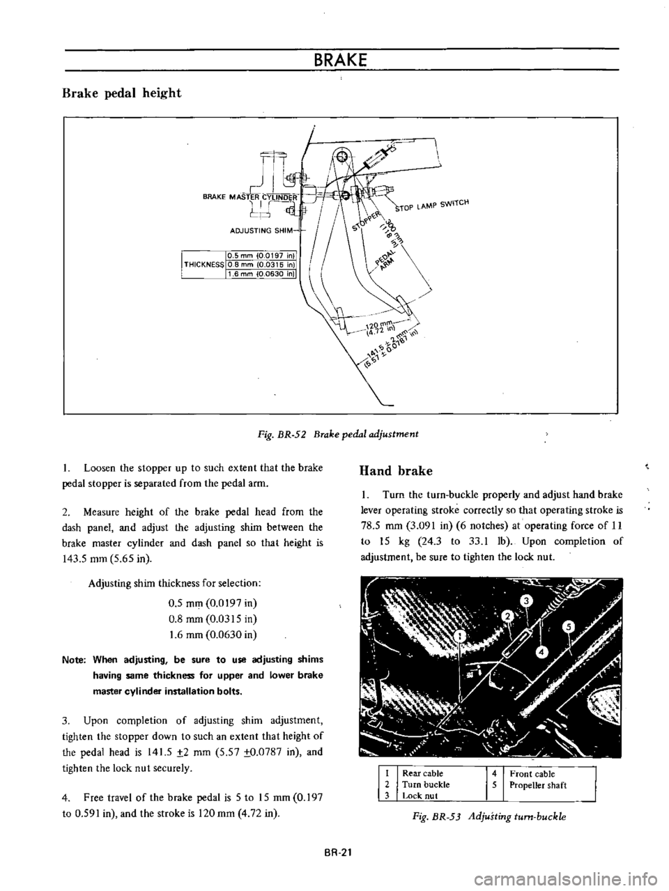
Fig
BR
52
Brake
pedal
adjustment
1
Loosen
the
stopper
up
to
such
extent
that
the
brake
pedal
stopper
is
separated
from
the
pedal
arm
2
Measure
height
of
the
brake
pedal
head
from
the
dash
panel
and
adjust
the
adjusting
shim
between
the
brake
master
cylinder
and
dash
panel
so
that
height
is
143
5
mm
5
65
in
Adjusting
shim
thickness
for
selection
0
5
mm
0
0197
in
0
8
mm
0
0315
in
1
6
mm
0
0630
in
Note
When
adjusting
be
sure
to
use
adjusting
shims
having
same
thickness
for
upper
and
lower
brake
master
cylinder
installation
bolts
3
Upon
completion
of
adjusting
shim
adjustment
tighten
the
stopper
down
to
such
an
extent
that
height
of
the
pedal
head
is
141
5
t2
mm
5
57
to
0787
in
and
tighten
the
lock
nut
securely
4
Free
travel
of
the
brake
pedal
is
5
to
15
mm
0
197
to
0
591
in
and
the
stroke
is
120
mm
4
72
in
Hand
brake
Turn
the
turn
buckle
properly
and
adjust
hand
brake
lever
operating
stroke
correctly
so
that
operating
stroke
is
78
5
mm
3
091
in
6
notches
at
operating
force
of
11
to
15
kg
24
3
to
33
1
1b
Upon
completion
of
adjustment
be
sure
to
tighten
the
lock
nut
I
I
Rear
cable
2
Turn
buckle
3
Lock
nut
1451
Front
cable
Propeller
shaft
Fig
BR
53
Adjusting
turn
buckle
BR
21
Page 157 of 513

CHASSIS
Tire
rotation
Tires
wear
unevenly
and
become
unbalanced
according
to
running
distance
Uneven
tire
wear
often
results
in
tire
noise
whkh
is
attributed
to
rear
axle
gears
bearing
ell
Meanwhile
the
front
tires
tend
to
wear
unevenly
because
of
front
wheel
alignment
Accordingly
to
equalize
tire
wear
it
is
necessary
to
rotate
tires
every
10
000
km
6
000
miles
of
operation
RIGHT
FRONT
RIGHT
REAR
r
1
Xl
L
J
LEFT
FRONT
LEFT
REAR
Fig
WT
2
Tire
rotation
The
tires
are
provided
with
tread
wear
indicator
at
six
places
around
tire
circumference
indicating
1
6
nun
0
16
in
tread
depth
When
the
tires
wear
and
then
the
marks
a
ppear
replace
them
with
new
ones
TREAD
WEAR
INDICATOR
7
TREAD
m
Y
X
W
X
v
w
WH024
Fig
WI
3
Tread
wear
illdicator
To
change
tire
with
wheel
using
a
jack
in
the
safe
manner
observe
the
following
procedures
I
Apply
parking
brake
and
block
front
wheels
when
rear
wheel
is
being
changed
2
Remove
wheel
cap
and
loosen
wheel
nuts
3
Place
jack
at
jacking
point
instructed
under
General
Information
and
raise
car
until
wheel
clears
ground
4
Remove
wheel
nuts
and
whed
from
drum
5
To
install
wheel
reverse
the
above
steps
Tighten
whed
nuts
in
criss
cross
fashion
to
8
0
to
9
0
kg
m
58
to
65
ft
lb
Note
Never
get
under
the
car
while
it
is
supported
only
by
the
jack
Always
use
safety
stands
to
support
the
side
member
of
body
construction
when
you
must
get
beneath
the
car
INSPECTION
Wheel
balance
The
wheel
and
tire
assembly
should
be
kept
balanced
statically
and
dynamically
Proper
tire
balance
is
necessary
when
driving
the
car
at
high
speeds
Consequently
the
wheel
and
tire
assembly
should
be
properly
rebalanced
whenever
puncture
is
repaired
The
wheel
and
tire
assembly
becomes
out
of
balance
according
to
uneven
tire
wear
Severe
acceleration
and
braking
or
fast
cornering
is
the
cause
of
wear
on
tire
resulting
in
unbalance
of
tire
and
wheel
assembly
The
symptom
of
unbalance
appears
as
tramp
car
shake
and
steering
trouble
To
correct
unbalance
use
proper
wheel
balancer
Maximum
allowable
unbalance
165
gr
cm
2
3
in
ol
at
rim
circumferences
Balance
weight
10
to
70
gr
0
35
to
2
47
Ol
at
10
gr
0
35
Ol
interval
Note
Be
sure
to
place
the
correct
balance
weights
on
the
inner
edge
of
rim
as
shown
in
Figure
WT
4
Wheel
and
tire
In
order
to
ensure
satisfactory
steering
condition
as
well
as
maximum
tire
life
proceed
as
follows
I
Check
wheel
rim
especially
rim
flange
and
bead
seat
for
rust
distortion
cracks
or
other
defects
which
might
cause
air
leaks
Function
of
tubeless
tire
depends
on
a
good
seal
between
tire
bead
and
wheel
rim
Thoroughly
remove
rust
dust
oxidized
rubber
or
sand
from
wheel
rim
with
wire
brush
emery
cloth
or
paper
Use
dial
gauge
to
examine
wheel
rim
for
lateral
and
diametral
run
out
WT
4
Page 161 of 513
STEERING
DESCRIPTION
The
steering
system
consists
of
recirculating
ball
type
gear
box
and
parallelogram
linkage
These
systems
give
good
response
light
handling
and
utmost
durability
Moreover
the
steering
linkage
is
equipped
with
a
torsion
rubber
system
idler
arm
which
absorbs
shock
from
the
wheel
Check
the
lubricant
of
gear
box
every
10
000
km
6
000
miles
and
replenish
recommended
oil
as
required
The
steering
linkage
should
be
greased
up
with
wheel
bearing
grease
every
50
000
km
30
000
miles
All
necessary
service
procedures
for
the
steering
lock
system
are
described
in
the
BODY
ELECTRICAL
SECTION
of
this
manual
and
therefore
no
instruction
is
given
here
STEERING
CONTENTS
REMOVAL
DISASSEMBL
Y
Ball
nut
assembly
ST
2
ST
3
ST
4
INSPECTION
AND
REPAIR
ASSEMBL
Y
AND
ADJUSTMENT
INSTALLATION
ST
4
ST
5
ST
7
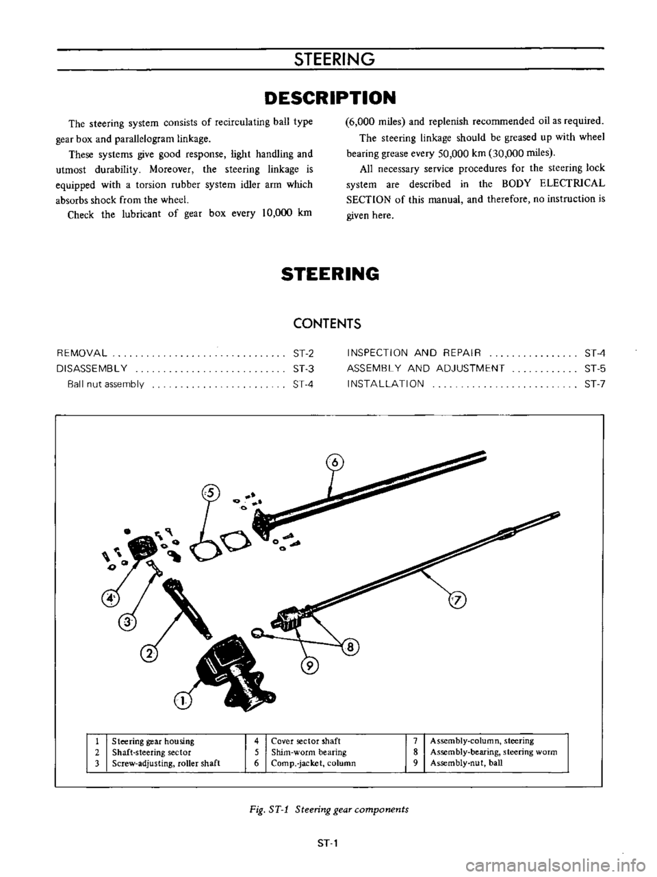
1
Steering
gear
housing
2
Shaft
steering
sector
3
Screw
adjusting
roller
shaft
4
Cover
sector
shaft
5
Shim
worm
bearing
6
Comp
jacket
column
7
Assembly
column
steering
8
Assembly
bearing
steering
worm
9
Assembly
nut
ball
Fig
ST
1
Steering
gear
components
ST
1
Page 162 of 513

Iii
I
o
t
I
I
CHASSIS
Fig
ST
2
Steering
wheel
REMOVAL
1
Remove
the
horn
ring
and
remove
the
steering
wheel
nut
and
pull
out
the
steering
wheel
by
the
use
of
a
Steer
ing
wheel
puller
ST27180000
3
Remove
the
turn
signal
and
lighting
switch
com
pletely
4
Remove
the
hand
lever
assembly
from
the
control
rod
assembly
by
unscrewing
the
fIxing
bolts
5
Remove
two
fIxing
bolts
used
to
secure
the
steering
column
to
the
instrument
panel
ST27180000
Fig
ST
3
Removing
steering
wheel
lock
nut
Note
The
horn
ring
can
be
easily
removed
by
two
bolts
2
Remove
the
steering
column
shell
Fig
ST
4
Removing
steering
column
upper
side
ST
2
Page 163 of 513
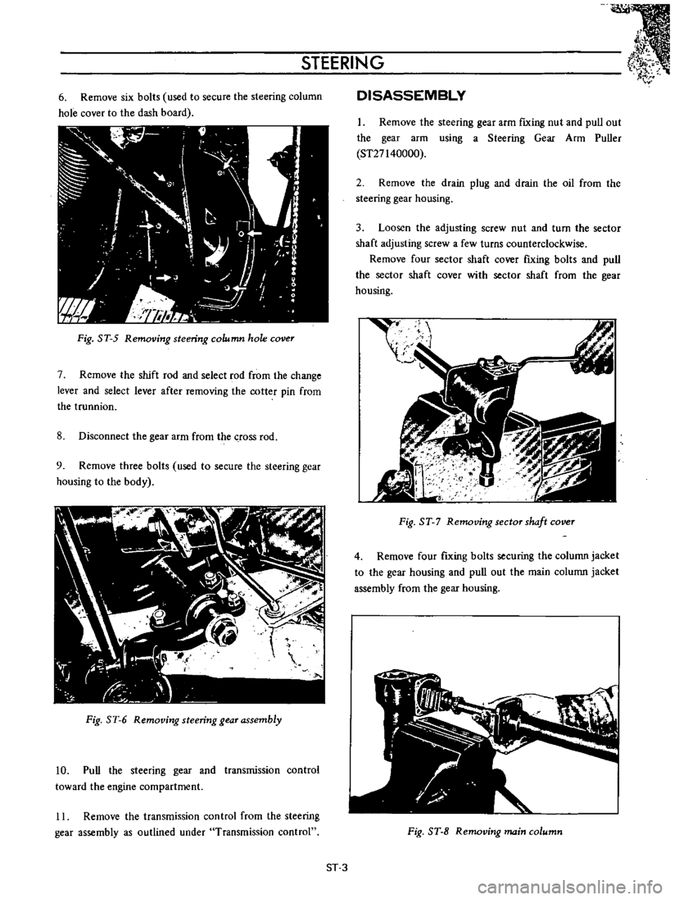
STEERING
6
Remove
six
bolts
used
to
secure
the
steering
column
hole
cover
to
the
dash
board
Fig
ST
5
Removing
steering
column
hole
cover
7
Remove
the
shift
rod
and
select
rod
from
the
change
lever
and
select
lever
after
removing
the
cotter
pin
from
the
trunnion
8
Disconnect
the
gear
arm
from
the
crOSS
rod
9
Remove
three
bolts
used
to
secure
the
steering
gear
housing
to
the
body
Fig
ST
6
Removing
steering
gear
assembly
10
Pull
the
steering
gear
and
transmission
control
toward
the
engine
compartment
11
Remove
the
transmission
control
from
the
steering
gear
assembly
as
outlined
under
Transmission
control
DISASSEMBLY
1
Remove
the
steering
gear
arm
fIxing
nut
and
pull
out
the
gear
arm
using
a
Steering
Gear
Arm
Puller
ST27140000
2
Remove
the
drain
plug
and
drain
the
oil
from
the
steering
gear
housing
3
Loosen
the
adjusting
screw
nut
and
turn
the
sector
shaft
adjusting
screw
a
few
turns
counterclockwise
Remove
four
sector
shaft
cover
fIxing
bolts
and
pull
the
sector
shaft
cover
with
sector
shaft
from
the
gear
housing
t
I
gJ
I
I
Fig
ST
7
Removing
sector
shaft
cover
4
Remove
four
fIxing
bolts
securing
the
column
jacket
to
the
gear
housing
and
pull
out
the
main
column
jacket
assembly
from
the
gear
housing
Fig
ST
8
Removing
main
column
ST
3