1973 DATSUN B110 lock
[x] Cancel search: lockPage 446 of 513
ENGINE
at
4
to
5
V
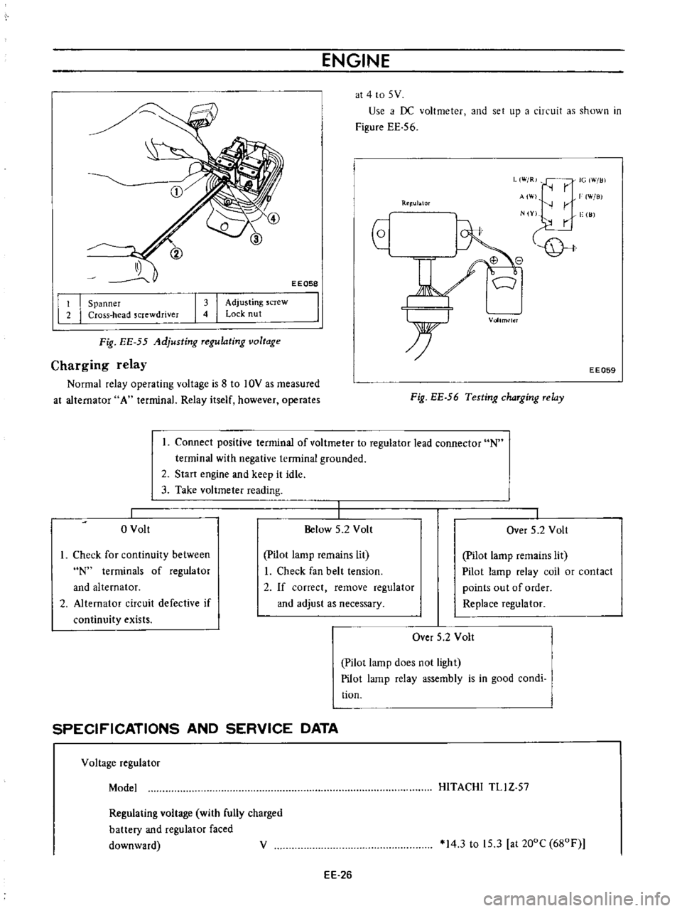
Use
i
f
DC
voltmeter
and
set
up
a
circuit
as
shown
in
Figure
EE
56
EEQ58
L
W
R
IG
Will
r
AI
W
lli
r
N
Y
vge
I
JJ
Rtl
ublOr
I
I
Spanner
Cross
head
screwdriver
I
I
Adjusting
screw
Lock
nut
Vollm
lcl
Fig
EE
55
Adjusting
Tegulating
voltage
Charging
relay
Normal
relay
operating
voltage
is
8
to
10V
as
measured
at
alternator
A
terminal
Relay
itself
however
operates
EE059
Fig
EE
56
Testing
chaTging
Telay
Connect
positive
terminal
of
voltmeter
to
regulator
lead
connector
N
terminal
with
negative
terminal
grounded
2
Start
engine
and
keep
it
idle
3
Take
voltmeter
reading
o
Volt
Below
5
2
Volt
I
Over
5
2
Volt
I
Check
for
continuity
between
N
terminals
of
regulator
and
alternator
2
Alternator
circuit
defective
if
continuity
exists
pilot
lamp
remains
lit
I
Check
fan
belt
tension
2
If
correct
remove
regulator
and
adjust
as
necessary
Pilot
lamp
remains
lit
Pilot
lamp
relay
coil
or
contact
points
out
of
order
Replace
regulator
Over
5
2
Volt
Pilot
lamp
does
not
light
Pilot
lamp
relay
assembly
is
in
good
condi
tion
SPECIFICATIONS
AND
SERVICE
DATA
Voltage
regulator
Model
HITACHI
TLl
Z
57
Regulating
voltage
with
fully
charged
battery
and
regulator
faced
downward
V
14
3
to
15
3
at
200C
680F
EE
26
Page 455 of 513
ENGINE
ElECTRICAL
SYSTEM
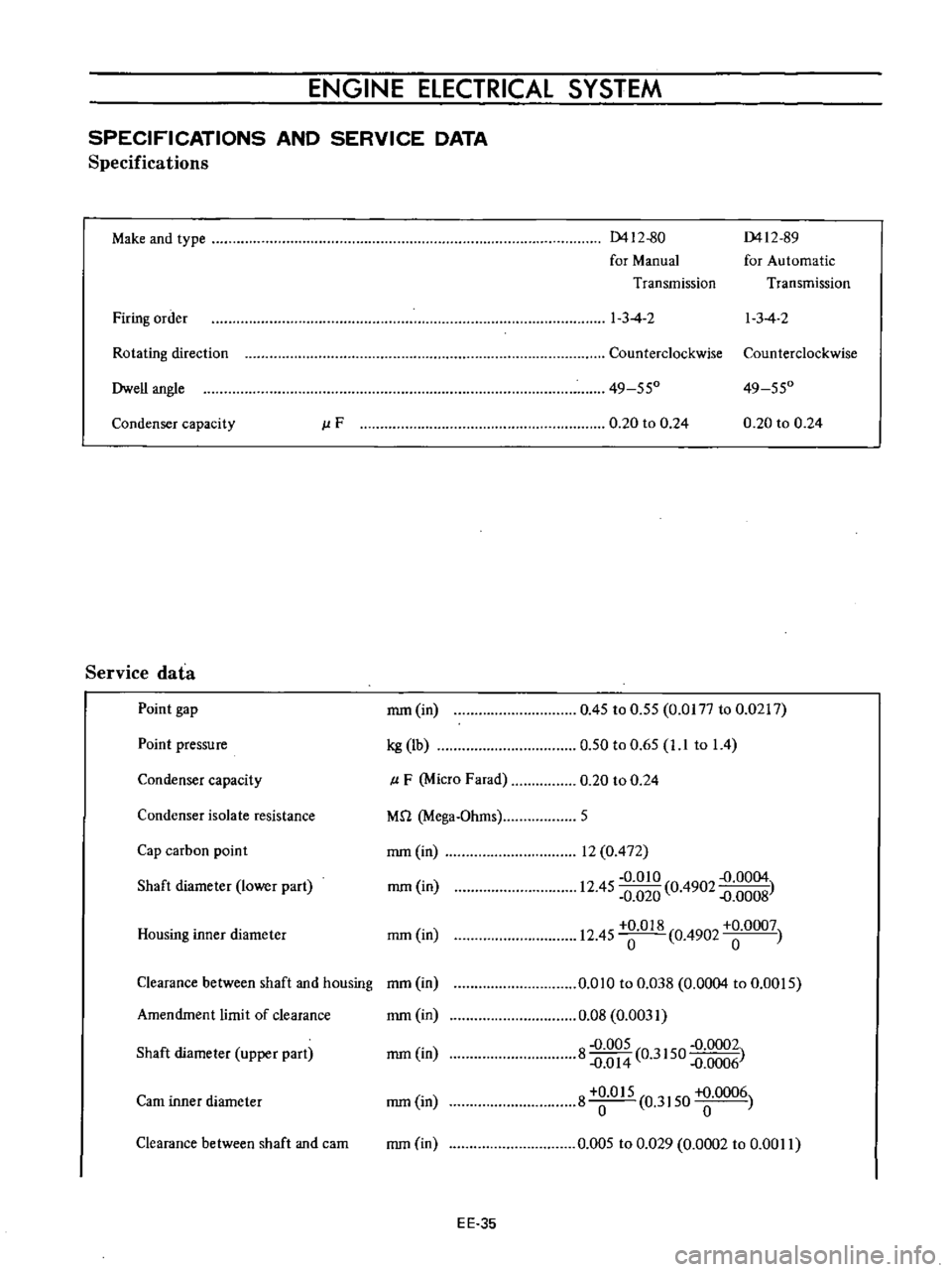
SPECIFICATIONS
AND
SERVICE
DATA
Specifications
Make
and
type
0412
80
0412
89
for
Manual
for
Automatic
Transmission
Transmission
Firing
order
1
3
4
2
I
3
4
2
Rotating
direction
Counterclockwise
Counterclockwise
Dwell
angle
49
550
49
550
Condenser
capacity
J
lF
0
20
to
0
24
0
20
to
0
24
Service
data
Point
gap
mm
in
0
45
to
0
55
0
0177
to
0
0217
0
50
to
0
65
1
1
to
1
4
Point
pressure
kg
lb
Condenser
capacity
p
F
Micro
Farad
0
20
to
0
24
Condenser
isolate
resistance
M
1
Mega
Ohms
5
Cap
carbon
point
mm
in
rom
in
Housing
inner
diameter
mm
in
12
0
472
0
010
D
0004
12
45
0
020
0
4902
D
0008
12
45
018
0
4902
0007
Shaft
diameter
lower
part
Clearance
between
shaft
and
housing
mm
in
Amendment
limit
of
clearance
mm
in
0
010
to
0
Q38
0
0004
to
0
0015
0
08
0
0031
8
0
005
0
3150
0
0002
D
O
14
D
0006
8
O
15
0
3150
0006
0
005
to
0
029
0
0002
to
0
00
II
Shaft
diameter
upper
part
mm
in
earn
inner
diameter
rom
in
Clearance
between
shaft
and
cam
mm
in
EE
35
Page 468 of 513
ENGINE
REMOVAL
INSTAllATION
5
Disconnecting
clutch
wire
on
right
hand
drive
model
On
left
hand
drive
model
disconnect
hydraulic
line
from
the
clutch
slave
cylinder
Disconnect
the
clutch
wire
at
the
portion
of
the
withdrawal
lever
See
the
section
covering
the
clutch
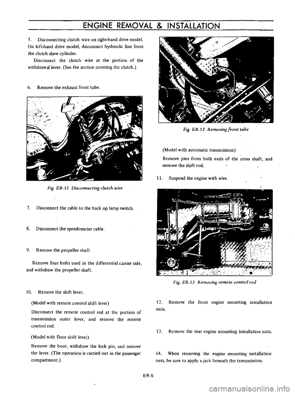
6
Remove
the
exhaust
front
tube
ij
f
I
Fig
ER
11
Disconnecting
dutch
wire
7
Disconnect
the
cable
to
the
back
up
lamp
switch
8
Disconnect
the
speedometer
cable
9
Remove
the
propeller
shaft
Remove
four
bolts
used
in
the
differential
carrier
side
and
withdraw
the
propeller
shaft
10
Remove
the
shift
lever
Model
with
remote
control
shift
lever
Disconnect
the
remote
control
rod
at
the
portion
of
transmission
outer
lever
and
remove
the
remote
control
rod
Model
with
floor
shift
lever
Remove
the
boot
withdraw
the
lock
pin
and
remove
the
lever
The
operation
is
carried
out
in
the
passenger
compartment
Fig
ER
12
Removing
fTont
tube
Model
with
automatic
transmission
Remove
pins
from
both
ends
of
the
cross
shaft
and
remove
the
shift
rod
II
Suspend
the
engine
with
wire
Fig
ER
13
Removing
remote
control
rod
12
Remove
the
front
engine
mounting
installation
nuts
13
Remove
the
rear
engine
mounting
installation
nuts
14
When
removing
the
engine
mounting
installation
nuts
be
sure
to
apply
a
jack
beneath
the
transmission
ER
5
Page 476 of 513
CHASSIS
fulcrum
type
The
mechanical
type
clutch
control
system
consists
of
pendent
clutch
pedal
clutch
control
cable
and
with
drawallever
The
withdrawal
lever
is
of
an
outer
fulcrum
type
which
provides
a
great
lever
ratio
and
thus
force
required
in
depressing
clutch
pedal
is
reduced
CLUTCH
PEDAL
Hydraulic
clutch
Removal
Remove
the
return
spring
2
Loosen
the
lock
nut
of
the
master
cylinder
push
rod
and
disconnect
the
push
rod
end
3
Remove
the
lock
nut
and
washer
of
the
pedal
shaft
and
remove
the
pedal
lever
Inspection
Thoroughly
clean
all
disassembled
parts
indicated
below
and
carefully
check
them
for
wear
damage
and
other
abnormal
conditions
Repair
or
replace
them
with
new
ones
if
required
f
fS
C5
J
dJ
YII
10
1
@
c
i
@
j
1
4
K
Clutch
pedal
free
trrlel
30
mm
1
181
nl
00
@
P
IO
Pedal
head
rubber
2
Return
spring
3
Pedal
lever
bush
4
Fulcrum
pedal
pin
etc
Reinstallation
Reinstall
the
clutch
pedal
in
reverse
sequence
of
removal
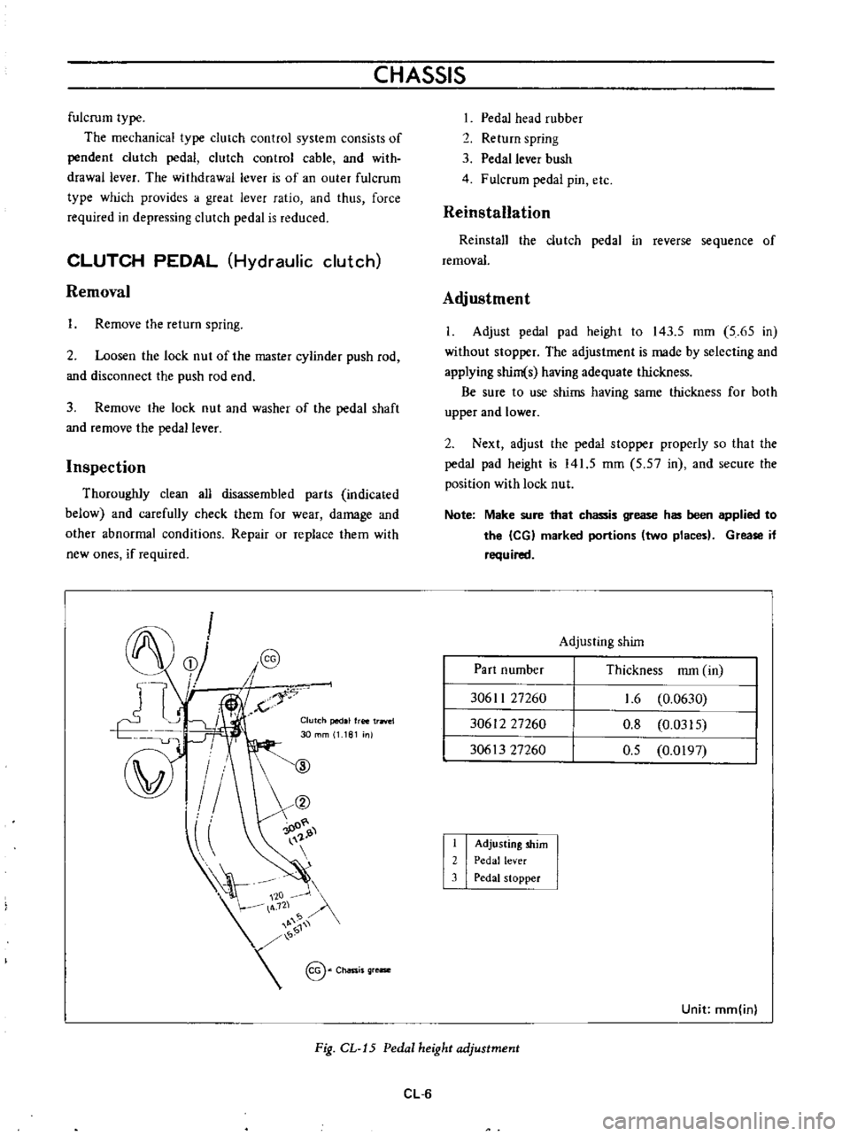
Adjustment
I
Adjust
pedal
pad
height
to
143
5
mm
5
65
in
without
stopper
The
adjustment
is
made
by
selecting
and
applying
shim
s
having
adequate
thickness
Be
sure
to
use
shims
having
same
thickness
for
both
upper
and
lower
2
Next
adjust
the
pedal
stopper
properly
so
that
the
pedal
pad
height
is
141
5
mm
5
57
in
and
secure
the
position
with
lock
nut
Note
Make
sure
that
chassis
grease
has
been
applied
to
the
leG
marked
portions
two
places
Grease
if
required
Adjusting
shim
Part
number
Thickness
mm
in
30611
27260
30612
27260
30613
27260
1
6
0
0630
0
8
0
0315
0
5
0
0197
I
2
3
Adjusting
shim
Pedal
lever
Pedal
stopper
Unit
mm
inl
Fig
CL
J5
Pedal
height
adjustment
CL
6
Page 477 of 513
CLUTCH
CLUTCH
PEDAL
AND
CLUTCH
CONTROL
CABLE
Mechanical
clutch
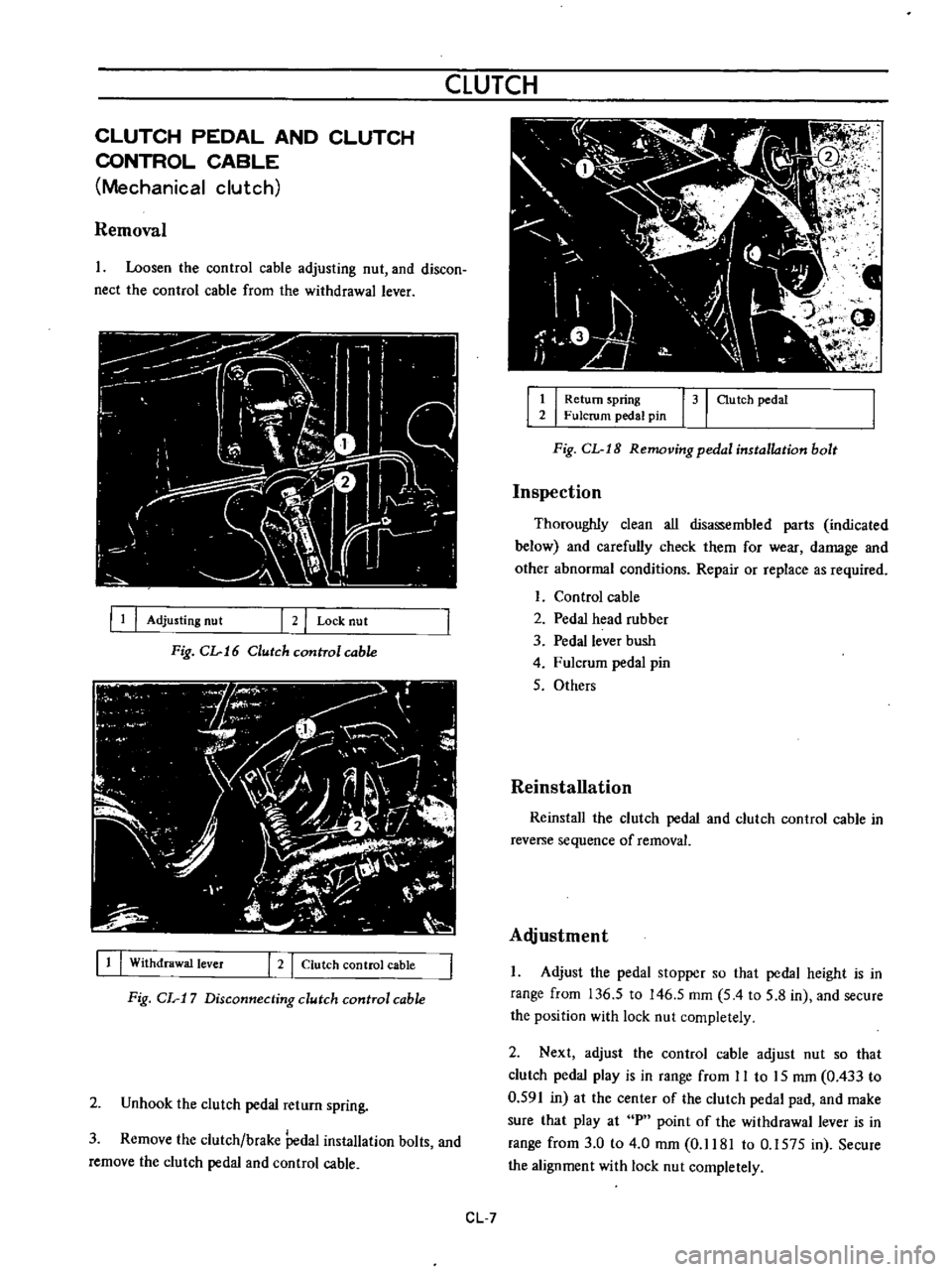
Removal
Loosen
the
control
cable
adjusting
nut
and
discon
nect
the
control
cable
from
the
withdrawal
lever
III
Adjusting
nut
2
I
Lock
nut
Fig
CL
16
Clutch
cunITol
cable
11
I
Withdrawal
lever
I
2
I
Clutch
control
cable
Fig
CL
17
Disconnecting
clutch
control
cable
2
Unhook
the
clutch
pedal
return
spring
3
Remove
the
clutch
brake
Pedal
installation
bolts
and
remove
the
clutch
pedal
and
control
cable
1
I
Return
spring
31
au
tch
pedal
2
Fulcrum
pedal
pin
Fig
CL
I8
Removing
pedal
installation
bolt
Inspection
Thoroughly
clean
all
disassembled
parts
indicated
below
and
carefully
check
them
for
wear
damage
and
other
abnormal
conditions
Repair
or
replace
as
required
Control
cable
2
Pedal
head
rubber
3
Pedal
lever
bush
4
Fulcrum
pedal
pin
5
Others
Reinstallation
Reinstall
the
clutch
pedal
and
clutch
control
cable
in
reverse
sequence
of
removal
Alljustment
Adjust
the
pedal
stopper
so
that
pedal
height
is
in
range
from
136
5
to
146
5
mm
5
4
to
5
8
in
and
secure
the
position
with
lock
nut
completely
2
Next
adjust
the
control
cable
adjust
nut
so
that
clutch
pedal
play
is
in
range
from
II
to
15
mm
0
433
to
0
591
in
at
the
center
of
the
clutch
pedal
pad
and
make
sure
that
play
at
P
point
of
the
withdrawal
lever
is
in
range
from
3
0
to
4
0
mm
0
1181
to
0
1575
in
Secure
the
alignment
with
lock
nut
completely
CL
7
Page 478 of 513
CHASSIS
i
I
I
I
II
I
I
J
u
IlllrP
Zll
I
ff
Pedal
play
11
to
15
I
0
433
to
0
591
I
W
p
da
stfO
l
e
1
P
point
end
play
l
e
A
1
C
3
0
to
A
O
Chassis
grease
20
0
1181
to
0
1575
I
Y
136
5
to
lA6
5
I
5
A
to
5
81
0
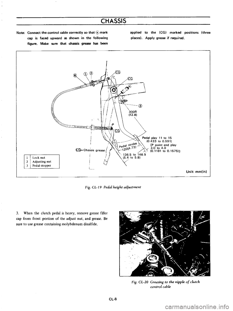
Note
Connect
the
control
cable
correctly
so
that
mark
cap
is
faced
upward
as
shown
in
the
following
figure
Make
sure
that
chassis
grease
has
been
I
2
3
Lock
nu
t
Adjusting
nut
Pedal
stopper
applied
to
the
CG
marked
positions
three
places
Apply
grease
if
required
@
300R
t2
8J
Unit
mm
in
Fig
CL
19
Pedal
height
adjustment
3
When
the
clutch
pedal
is
heavy
remove
grease
filler
cap
from
front
portion
of
the
adjust
nut
and
grease
Be
sure
to
use
grease
containing
molybdenum
disulfide
Fig
CL
20
Greasing
to
the
nipple
of
clutch
control
cable
CL
8
Page 480 of 513
CHASSIS
2
Apply
brake
fluid
sufficiently
to
the
cylinder
and
piston
and
assemble
them
Reinstallation
Reinstall
the
master
cylinder
assembly
in
reverse
sequence
of
removal
and
adjust
as
follows
I
Adjust
the
pedal
height
by
changing
the
push
rod
length
2
B
eed
air
out
of
the
hydraulic
system
OPERATING
CYLINDER
Hydraulic
clutch
Removal
Remove
the
return
spring
2
Disconnect
the
clutch
line
from
the
operating
cyl
inder
3
Disconnect
the
push
rod
from
the
withdrawal
lever
4
Release
two
bolts
used
to
mount
the
operating
cylinder
to
the
clutch
housing
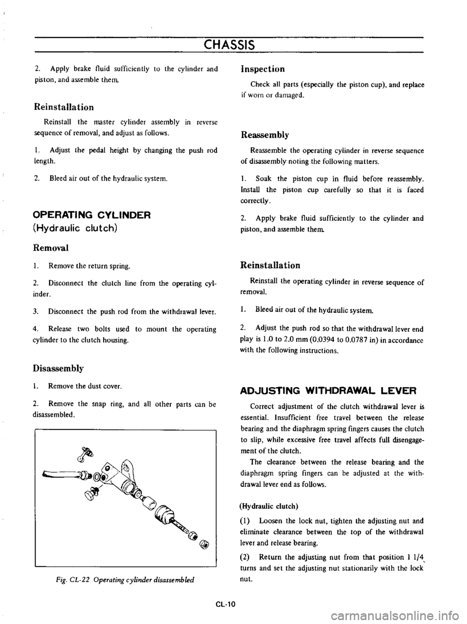
Disassembly
1
Remove
the
dust
cover
2
Remove
the
snap
ring
and
all
other
parts
can
be
disassembled
@
Fig
CL
22
Operating
cylinder
disassembled
CL
10
Inspection
Check
all
parts
especially
the
piston
cup
and
replace
if
worn
or
damaged
Reassembly
Reassemble
the
operating
cylinder
in
reverse
sequence
of
disassembly
noting
the
following
matters
Soak
the
piston
cup
in
fluid
before
reassembly
Install
the
piston
cup
carefully
so
that
it
is
faced
correctly
2
Apply
brake
fluid
sufficiently
to
the
cylinder
and
piston
and
assemble
them
Reinstallation
Reinstal
the
operating
cylinder
in
reverse
sequence
of
removal
1
Bleed
air
out
of
the
hydraulic
system
2
Adjust
the
push
rod
so
that
the
withdrawal
lever
end
play
is
0
to
2
0
mm
0
0394
to
0
0787
in
in
accordance
with
the
following
instructions
AD
USTING
WITHDRAWAL
LEVER
Correct
adjustment
of
the
clutch
withdrawal
lever
is
essential
Insufficient
free
travel
between
the
release
bearing
and
the
diaphragm
spring
fingers
causes
the
clutch
to
slip
while
excessive
free
travel
affects
full
disengage
ment
of
the
clutch
The
clearance
between
the
release
bearing
and
the
diaphragm
spring
fingers
can
be
adjusted
at
the
with
drawallever
end
as
follows
Hydraulic
clutch
Loosen
the
lock
nut
tighten
the
adjusting
nut
and
eliminate
clearance
between
the
top
of
the
withdrawal
lever
and
release
bearing
2
Return
the
adjusting
nut
from
that
position
I
4
turns
and
set
the
adjusting
nut
stationarily
with
the
lock
nut
Page 481 of 513
CLUTCH
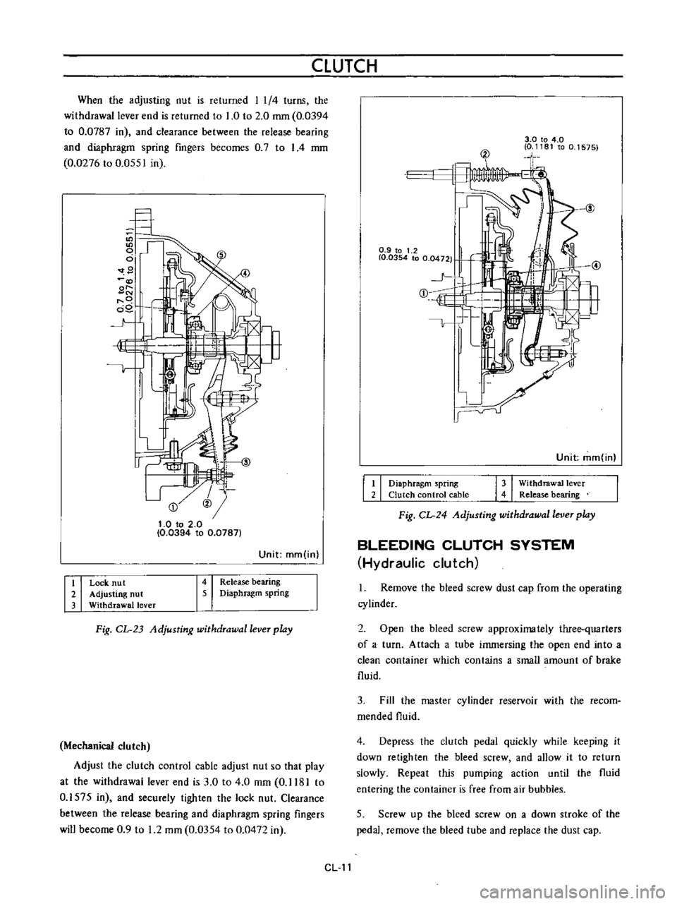
When
the
adjusting
nut
is
returned
I
1
4
turns
the
withdrawal
lever
end
is
returned
to
1
0
to
2
0
mm
0
0394
to
0
0787
in
and
clearance
between
the
release
bearing
and
diaphragm
spring
fingers
becomes
0
7
to
I
4
mm
0
0276
to
0
0551
in
9
@
t
O
to
2
0
0
0394
to
0
0787
Unit
mm
in
I
i
I
I
I
Release
bearing
Diaphragm
spring
Lock
nu
t
Adjusting
nut
Withdrawal
lever
Fig
CL
23
Adjusting
withdrawal
lever
play
Mechanical
clutch
Adjust
the
clutch
control
cable
adjust
nut
so
that
play
at
the
withdrawal
lever
end
is
3
0
to
4
0
mm
0
1181
to
0
1575
in
and
securely
tighten
the
lock
nut
Clearance
between
the
release
bearing
and
diaphragm
spring
fingers
will
become
0
9
to
1
2
mm
0
0354
to
0
0472
in
3
0
to
4
0
0
1181
to
0
1575
@
0
9
to
1
2
I
0
0354
to
0
0472
1
j
E
1
Unit
mm
in
I
I
I
I
Diaphragm
spring
Clutch
control
cable
Withdrawal
lever
Release
bearing
Fig
CL
24
Adjusting
withdrawal
lever
play
BLEEDING
CLUTCH
SYSTEM
Hydraulic
clutch
1
Remove
the
bleed
screw
dust
cap
from
the
operating
cylinder
2
Open
the
bleed
screw
approximately
three
quarters
of
a
turn
Attach
a
tube
immersing
the
open
end
into
a
clean
container
which
contains
a
small
amount
of
brake
fluid
3
Fill
the
master
cylinder
reservoir
with
the
recom
mended
fluid
4
Depress
the
clutch
pedal
quickly
while
keeping
it
down
retighten
the
bleed
screw
and
allow
it
to
return
slowly
Repeat
this
pumping
action
until
the
fluid
entering
the
container
is
free
from
air
bubbles
5
Screw
up
the
bleed
screw
on
a
down
stroke
of
the
pedal
remove
the
bleed
tube
and
replace
the
dust
cap
CL
11