1973 DATSUN B110 brake
[x] Cancel search: brakePage 61 of 513
AUTOMATIC
TRANSMISSIO
N
Trouble
IA
BCD
IE
F
G
H
IIJ
K
L
1M
NO
P
1m
n
q
riB
t
u
v
w
x
y
No
shock
at
changing
from
I
to
7
5
@
@
I
1
2
3
4
1
6
I
2
range
or
engine
extremely
races
Failure
to
change
from
3rd
to
2nd
1
2
4
5
7
16
3
I
@@
@
by
turning
lever
into
I
range
Engine
brake
does
not
operate
in
I
2
4
5
3
@
J
I
range
Gear
change
from
1st
to
2nd
or
from
2nd
to
3rd
in
I
I
2
@
range
Does
not
change
from
2nd
1
2
456
7
3
@
@
to
1st
in
I
range
Large
shock
changing
from
2nd
1
2
4
3
IDI
to
1st
in
I
range
Vehicle
will
move
when
changing
into
P
range
or
parking
gear
does
not
1
@
disengage
by
turning
off
P
range
Transmission
overheats
1
3
4
12
6
8
7
5
@@@I@@
@
Oil
shoots
out
during
run
@@@
@@
@
White
smoke
issues
out
from
tail
1
3
5
6
2
7
8
4
pipe
during
run
Offensive
smell
at
oil
charging
11
2
I@
@
ID@I
J
@@
@
pipe
Transmission
noise
in
P
and
N
1
2
I
I@
ranges
Transmission
noise
in
0
2
I
1
2
@
@
@
@
and
R
ranges
AT
57
Page 62 of 513
CHASSIS
Trouble
shooting
guide
for
3N71B
Automatic
Transmission
Order
Test
item
Checking
Oil
level
gauge
2
Downshift
solenoid
3
ManuaIlinkage
4
Inhibitor
switch
5
Engine
idling
rpm
6
Vacuum
pressure
of
vacuum
pipe
7
Operation
in
each
range
8
Creep
of
vehicle
Stall
lest
Oil
pressure
before
testing
2
Stall
test
3
Oil
pressure
after
testing
Road
test
Slow
acceleration
Ist
2nd
2nd
3rd
2
Quick
acceleration
Ist
2nd
2nd
3rd
3
Kick
down
operation
3rd
2nd
or
2nd
1st
Procedure
Check
gauge
for
oil
level
and
leakage
before
and
after
each
test
Check
by
sound
whether
solenoid
operates
when
depressing
accelerating
pedal
fully
with
ignition
key
ON
Check
changing
conditions
into
P
R
N
D
2
and
I
ranges
by
moving
selector
lever
Check
whether
starter
operates
in
N
and
tp
ranges
only
and
whether
reverse
lamp
operates
in
R
range
only
Check
whether
idling
rpm
meet
standard
Checking
whether
vacuum
pressure
is
more
than
450
mmHg
in
idling
and
whether
it
decreases
with
increasing
rpm
Check
whether
transmission
engages
positively
by
shifting
N
o
D
N
2
N
I
and
N
R
range
while
idling
with
brake
applied
Check
whether
there
is
any
creep
in
D
2
I
and
R
ranges
2
1
and
R
range
Measure
line
pressures
in
D
while
idling
Measure
engine
rpm
and
line
pressure
in
D
2
I
and
R
ranges
during
fullthrallIe
operation
Notes
a
Temperature
of
torque
converter
oil
used
in
test
should
be
from
600
to
lOOoC
1400
to
2120F
i
e
sufficiently
warmed
up
but
not
overheated
b
For
cooling
oil
between
each
stall
test
for
D
2
1
and
R
ranges
idle
engine
i
e
rpm
at
about
1
200
rpm
for
more
than
1
minute
in
P
range
Measurement
time
must
not
be
more
than
5
secon
Same
as
the
item
I
Check
vehicle
speeds
and
engine
rpm
in
shifting
up
1st
2nd
range
and
2nd
J
3rd
range
while
running
with
lever
in
D
range
and
engine
vacuum
pressure
of
about
200
mmHg
Same
as
the
item
1
above
except
with
engine
vacuum
pressure
of
0
mmHg
i
e
in
position
just
before
kick
down
Check
whether
the
kick
down
operates
and
measure
the
time
delays
while
running
at
30
40
50
60
70
km
h
19
25
31
38
44
MPH
in
D
range
AT
58
Page 64 of 513

CHASSIS
SERVICE
DATA
AND
SPECIFICATIONS
General
specifications
Torque
converter
Type
Stall
torque
ratio
Transmission
Type
Control
elements
Gear
ratio
Selector
positions
Oil
pump
Type
Number
of
pump
Oil
Capacity
Hydraulic
control
system
Lubrication
system
Cooling
system
Multiple
disc
clutch
Band
brake
Multiple
disc
brake
One
way
clutch
1st
lnd
3rd
Reverse
P
Park
R
Reverse
N
Neutral
D
Drive
1
lnd
lock
I
Lock
up
AT
60
Symmetrical3
element
I
stage
l
phase
torque
converter
coupling
2
0
I
3
speed
forward
and
one
speed
reverse
with
planetary
gear
train
1
I
I
I
2
458
1
458
1
000
2
182
The
transmission
is
placed
in
neutral
The
output
shaft
is
fixed
The
engine
can
be
started
Backward
running
The
transmission
is
in
neutral
The
engine
can
be
started
Up
or
downshifts
automatically
to
and
from
1st
lnd
and
top
Fixed
at
2nd
Fixed
at
low
or
downshifts
from
2nd
Internally
intermeslting
involute
gear
pump
Automatic
transmission
fluid
Dexron
type
5
5
liters
57
8
U
S
qts
47
8
Imp
qts
Approximately
1
7
liters
27
8
U
S
qts
2
3
8
Imp
qts
in
torque
converter
Controlled
by
detecting
the
negative
pressure
of
intake
manifold
and
the
revolution
speed
of
output
shaft
Forced
lubrication
by
an
oil
pwnp
Air
cooled
Page 65 of 513
AUTOMATIC
TRANSMISSION
Specifications
and
adjustment
Automatic
transmission
assembly
Model
code
number
Torque
converter
assembly
Stamped
mark
on
the
TIC
Front
clu
tch
Number
of
drive
plate
Number
of
driven
plates
Clearance
Thickness
of
retaining
plate
Rear
clutch
Number
of
drive
plates
Number
of
driven
plate
Clearance
Thickness
of
retaining
plate
Low
reverse
brake
Number
of
drive
plates
Number
of
driven
plates
Clearance
Thickness
of
retaining
plate
Brake
band
Piston
size
Big
dia
Small
dia
Control
valve
assembly
Stamped
mark
on
trainer
Governor
assembly
Stamped
mark
on
governor
body
mm
in
mm
in
mm
in
mm
in
mm
in
mm
in
mm
in
AT
61
x
0100
IO
C
3
3
1
6
to
1
8
0
0630
to
0
071
10
6
0
417
10
8
0
425
11
0
0
433
11
2
0
441
II
4
0
449
11
6
0
457
3
3
1
0
to
1
5
0
039
to
0
059
8
35
0
3287
3
3
0
80
to
1
05
0
0315
to
0
0413
15
8
0
622
16
0
0
630
16
2
0
638
16
4
0
646
16
6
0
654
16
8
0
661
64
2
520
44
I
732
E
35
Page 66 of 513
CHASSIS
Engine
idling
and
stall
revolution
Engine
with
emission
control
device
Idling
revolution
rpm
650
at
0
position
800
at
N
position
1
750
to
2
000
Stall
revolution
rpm
Tightening
torque
kg
m
ft
Ib
Test
plug
oil
pressure
inspection
hole
Support
actuator
parking
rod
inserting
position
to
rear
extension
Oil
charging
pipe
to
case
Dust
cover
to
converter
housing
Selector
range
lever
to
manual
shaft
Lower
shift
rod
lock
nut
6
5
t07
5
47
to
54
0
8
to
1
0
5
8
to
7
2
4
0
to
5
0
30
to
36
4
0
to
5
0
30
to
36
2
0
to
2
5
15
to
18
0
5
to
0
7
3
6
to
5
1
0
5
to
0
7
3
6toS
I
1
2
to
1
5
8
7
to
10
8
1
5
to
4
0
II
to
29
1
3
to
1
8
9
4
to
13
0
55
to
0
75
4
0
to
5
4
0
25
to
0
35
1
9
to
2
5
0
25
to
0
35
1
9
to
2
5
0
5
to
0
7
3
6
to
5
I
0
25
to
0
35
1
9
to
2
5
0
5
to
0
7
3
6
to
5
1
0
6
to
0
8
4
4
to
5
8
0
5
to
0
7
3
6
to
5
1
3
0
to
4
0
22
to
29
3
0
to
5
0
22
to
36
14
to
2
1
10
to
15
0
8
to
l
l
5
8
to
7
9
0
55
to
0
75
4
0
to
5
4
0
55
to
0
75
4
0
to
5
4
3
0
to
4
0
22
to
29
2
0
to
2
9
15
to
21
Drive
plate
to
crankshaft
Drive
plate
to
torque
converter
Converter
housing
to
engine
Transmission
case
to
converter
housing
Transmission
case
to
rear
extension
Oil
pan
to
transmission
case
Servo
piston
retainer
to
transmission
case
Piston
stem
when
adjuting
band
brake
Piston
stem
lock
nut
One
way
clutch
inner
race
to
transmission
case
Control
valve
body
to
transmission
case
Lower
valve
body
to
upper
valve
body
Side
plate
to
control
valve
body
Nut
for
control
valve
reamer
bolt
Oil
strainer
to
lower
valve
body
Governor
valve
body
to
oil
distributor
Oil
pump
housing
to
oil
pump
cover
Inhibitor
switch
to
transmh
sion
case
Manual
shaft
lock
nut
Oil
tube
to
transmission
case
Turn
back
two
turns
after
tightening
AT
62
Page 88 of 513
CHASSIS
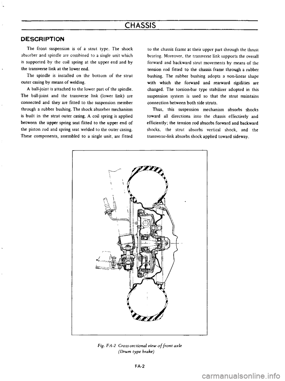
DESCRIPTION
The
front
suspension
is
of
a
strut
lype
The
shock
absurber
and
spindle
are
combined
to
a
single
unit
which
is
supported
by
the
coil
spring
at
the
upper
end
aod
by
the
transverse
link
at
the
lower
end
The
spindle
is
ins
tailed
on
the
bottom
of
the
strut
outer
casing
by
means
of
welding
A
ball
joint
is
attached
to
the
lower
part
of
the
spindle
The
ball
joint
and
the
transverse
link
lower
link
are
connected
and
they
are
fitted
to
the
suspension
member
through
a
rubber
bushing
The
shock
absorber
mechanism
is
built
in
the
strut
outer
casing
A
coil
spring
is
applied
between
the
upper
spring
seat
filled
to
the
upper
end
of
the
piston
rod
and
spring
seat
welded
to
the
outer
casing
These
components
assembled
to
a
single
unit
are
fitted
tu
the
chassis
frame
at
their
upper
part
through
the
thrust
bearing
Moreover
the
transverse
link
supports
the
overall
forward
and
backward
strut
movements
by
means
of
the
tension
rod
filled
to
the
chassis
frame
through
a
rubber
bushing
The
rubber
bushing
adopts
a
non
linear
shape
with
which
the
forward
and
rearward
rigidities
are
changed
The
torsion
bar
type
stabilizer
adopted
in
this
suspension
system
is
used
so
that
the
strut
maintains
connection
between
both
side
struts
Thus
this
suspension
mechanism
absorbs
shocks
toward
all
directions
into
the
chassis
effectively
and
efficiently
the
tension
rod
absorbs
forward
and
backward
shocks
the
strut
absorbs
vertical
shock
and
the
transverse
link
absorbs
shock
applied
toward
sideway
t
J
f
II
L
II
I
7
f
1
I
Fig
F
1
2
Cross
sectional
view
of
front
axle
Drum
type
brake
FA
2
Page 89 of 513
FRONT
AXLE
FRONT
SUSPENSION
FRONT
AXLE
AND
SUSPENSION
ASSEMBLY
Removal
1
Jack
up
the
vehicle
and
support
the
vehicle
with
stands
See
the
Section
GL
2
Remove
the
hub
nuts
and
remOve
the
wheel
3
Remove
the
splash
board
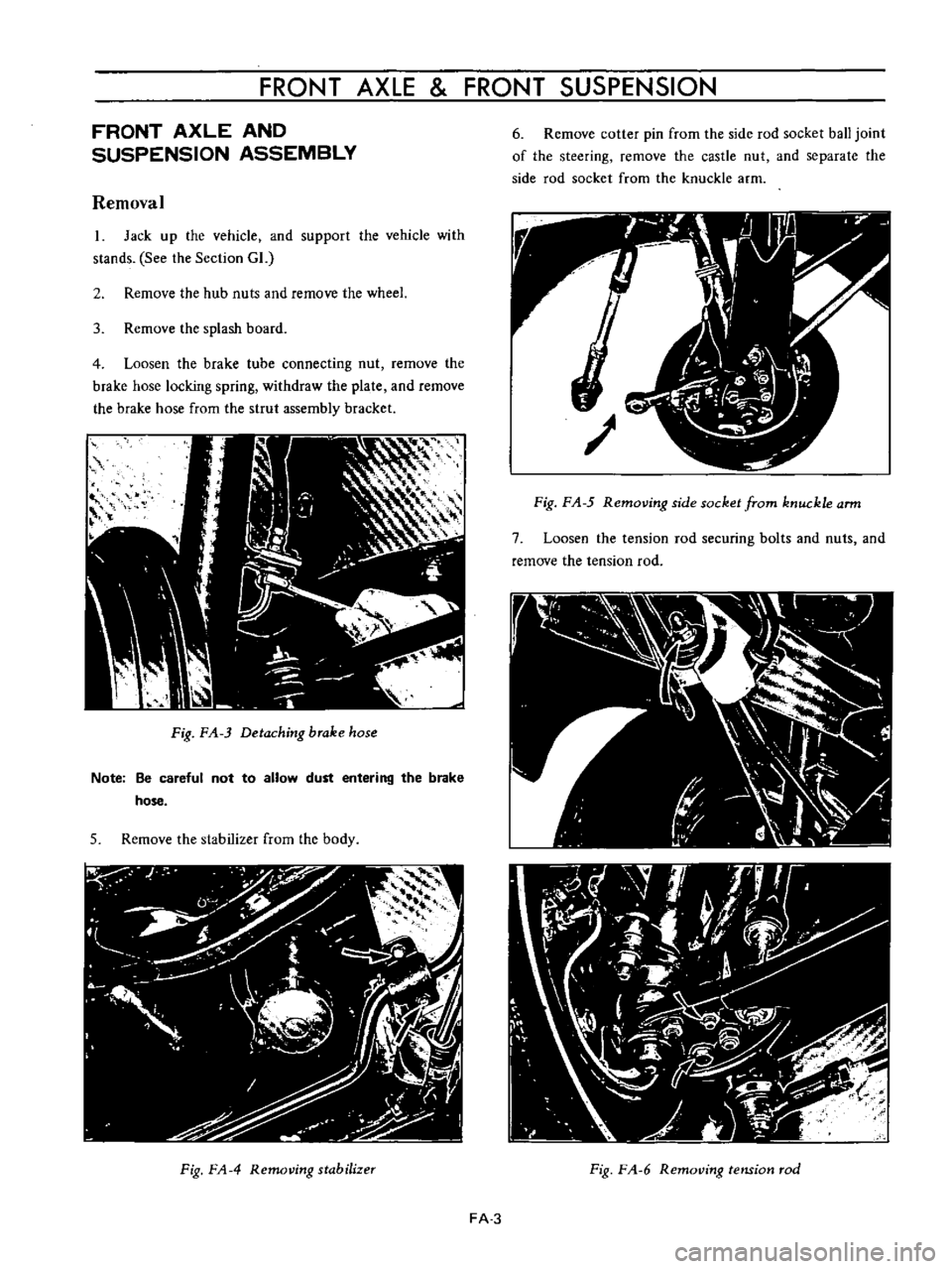
4
Loosen
the
brake
tube
connecting
nut
remove
the
brake
hose
locking
spring
withdraw
the
plate
and
remOve
the
brake
hose
from
the
strul
assembly
bracket
Fig
FA
3
Detaching
brake
hose
Note
Be
careful
not
to
allow
dust
entering
the
brake
hose
5
Remove
the
stabilizer
from
the
body
Fig
FA
4
Removing
stabilizer
6
Remove
cotter
pin
from
the
side
rod
socket
ball
joint
of
the
steering
remove
the
castle
nut
and
separate
the
side
rod
socket
from
the
knuckle
arm
Fig
F
A
5
Removing
side
socket
from
knuckle
arm
7
Loosen
the
tension
rod
securing
bolts
and
nuts
and
remove
the
tension
rod
Fig
F
A
6
RemotJing
tension
rod
FA
3
Page 92 of 513

CHASSIS
Tightening
torque
of
front
suspension
cross
member
and
body
is
3
2
to
4
0
kg
m
23
1
to
28
9
ft
Ib
5
Tightening
torque
of
bolt
used
to
secure
the
upper
portion
of
the
strut
assembly
on
the
body
is
1
6
to
2
1
kg
m
11
6
to
15
2ft
lb
FRONT
AXLE
Removal
I
Jack
up
the
vehicle
remove
the
wheel
and
discon
nect
the
brake
hose
at
the
strut
outer
casing
bracket
unit
For
details
see
Removal
of
front
axle
and
suspension
assembly
2
Remove
the
brake
caliper
installation
bolts
and
remove
the
caliper
assembly
Disc
type
brake
3
Remove
the
brake
druOL
Drum
type
brake
4
Remove
the
hub
cap
with
a
flal
headed
screwdriver
or
other
proper
tool
and
hammer
Be
sure
to
tap
lightly
5
Remove
cotter
pin
from
the
wheel
bearing
lock
nut
and
remove
the
lock
nut
6
With
the
wheel
bearing
washer
and
wheel
bearing
installed
on
the
wheel
hub
remove
the
wheel
hub
from
the
spindle
In
the
case
of
a
disc
type
brake
the
wheel
hub
may
be
removed
with
the
disc
rotor
installed
on
the
wheel
hub
Fig
FA
17
Removing
wheel
hub
7
Remove
the
return
spring
and
brake
shoes
remove
brake
disc
assembly
installation
bolts
and
remove
the
brake
disc
assembly
from
the
spindle
Drum
type
brake
Fig
FA
IS
Removing
brake
disc
a
ssembly
8
Remove
baffle
plate
set
screws
and
remove
the
baffle
plate
Disc
type
brake
Fig
FA
19
Removingbaffleplate
9
Utilizing
two
grooves
inside
the
wheel
hub
tap
and
remove
the
wheel
bearing
outer
race
from
the
hub
Fig
FA
20
Removing
wheel
bearing
outer
race
FA
6