Page 93 of 513
FRONT
AXLE
FRONT
SUSPENSION
10
Remove
four
brake
disc
fitting
bolts
and
remove
the
brake
disc
rotor
from
the
wheel
hub
assembly
Disc
type
b
rake
Inspection
1
Grease
seal
I
ycQ
r
A
1
r
j
t
I
I
i
I
When
grease
leakage
is
delected
during
disassembly
replace
2
Replace
the
grease
seal
with
a
new
one
if
worn
or
cracked
Fig
FA
21
Removing
brake
disc
rotor
2
Wheel
bearing
Remove
used
grease
from
the
wheel
bearing
with
solvent
and
inspect
the
bearing
for
operating
condition
from
the
rotation
operating
sound
and
appearance
The
outer
race
may
be
checked
for
the
condition
of
rolling
surface
with
the
race
installed
on
the
wheel
hub
Visual
serviceability
judgement
standard
for
the
wheel
bearing
is
indicated
in
the
following
table
Visual
Serviceability
Judg
ment
Standard
for
Wheel
Bearing
INNER
RACE
SURFACE
OUTER
RACE
FITTED
SURFACE
COLLAR
SURFACE
OUTER
RACE
SURFACE
INNER
RACE
FITTED
ROLLER
ROLLING
SURFACE
SURFACE
SMALL
COLLAR
INNER
RACE
LARGE
COLLAR
ROLLER
SUPPORTER
OUTER
RACE
FA
7
Page 97 of 513

FRONT
AXLE
FRONT
SUSPENSION
t
t
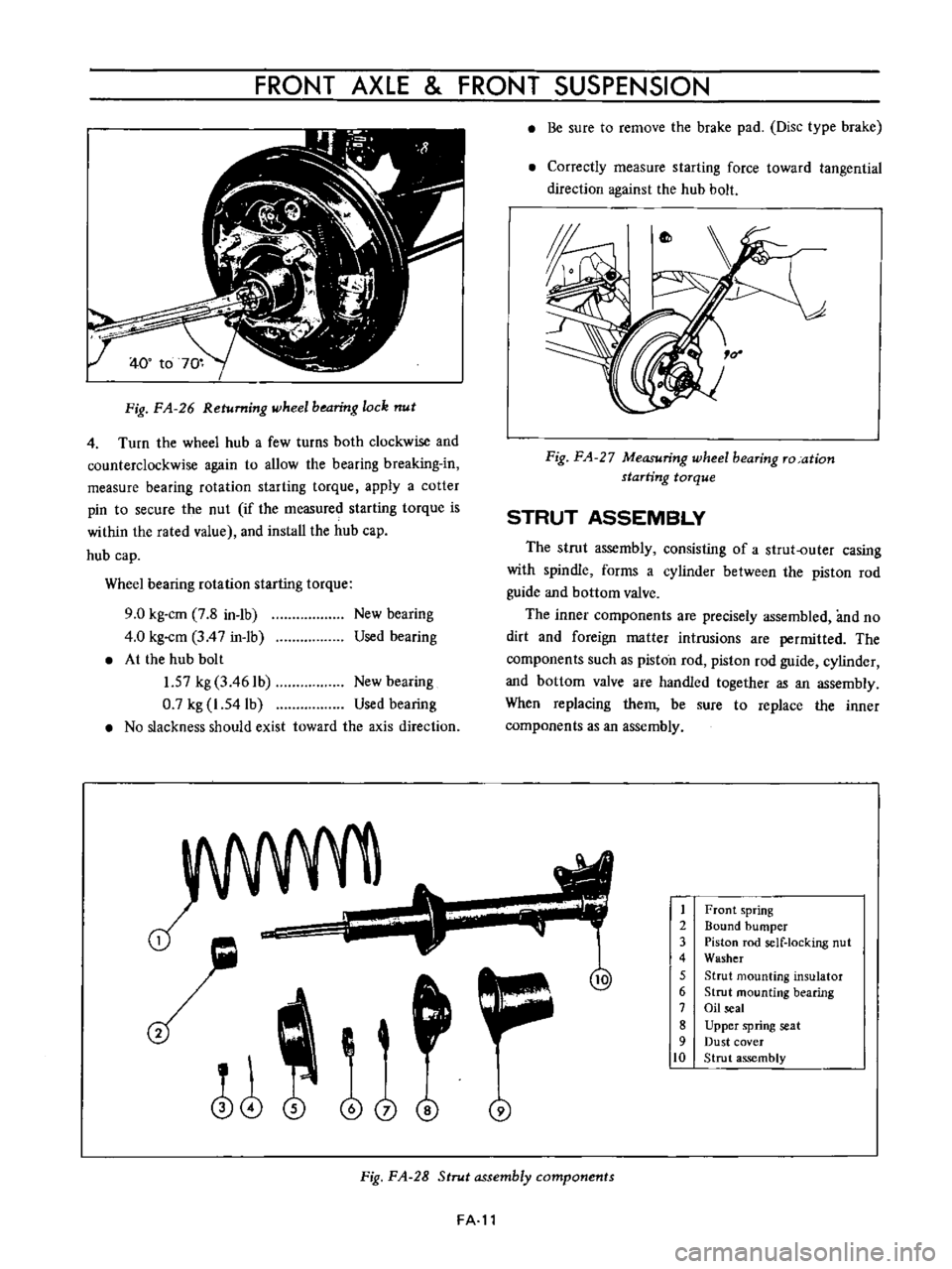
Fig
FA
26
Returning
wheel
bearing
lock
nut
4
Turn
the
wheel
hub
a
few
turns
both
clockwise
and
counterclockwise
again
to
allow
the
bearing
breaking
in
measure
bearing
rotation
starting
torque
apply
a
cotter
pin
to
secure
the
nut
if
the
measured
starting
torque
is
within
the
rated
value
and
install
the
hub
cap
hub
cap
Wheel
bearing
rotation
starting
torque
9
0
kg
cm
7
8
in
1b
4
0
kg
cm
3
4
7
in
1b
At
the
hub
bolt
1
57
kg
3
461b
New
bearing
0
7
kg
1
54lb
Used
bearing
No
slackness
should
exist
toward
the
axis
direction
New
bearing
Used
bearing
J
o
i
@
j
Be
sure
to
remove
the
brake
pad
Disc
type
brake
Correctly
measure
starting
force
toward
tangential
direction
against
the
hub
bolt
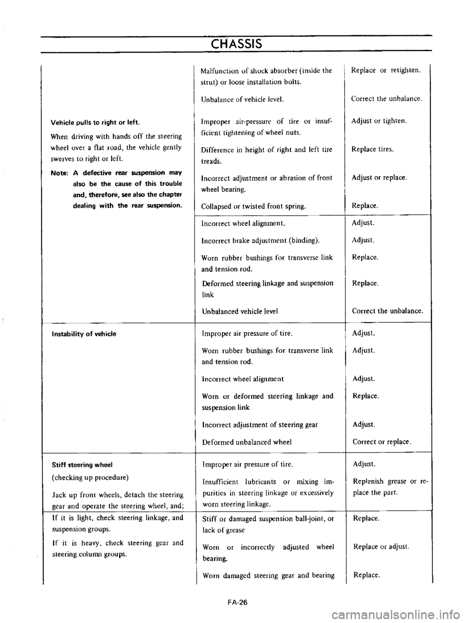
Fig
FA
27
Measuring
wheel
bearing
ro
ation
starting
torque
STRUT
ASSEMBLY
The
strut
assembly
consisting
of
a
strut
outer
casing
with
spindle
forms
a
cylinder
between
the
piston
rod
guide
and
bottom
valve
The
inner
components
are
precisely
assembled
and
no
dirt
and
foreign
matter
intrusions
are
permitted
The
components
such
as
piston
rod
piston
rod
guide
cylinder
and
bottom
valve
are
handled
together
as
an
assembly
When
replacing
them
be
sure
to
replace
the
inner
components
as
an
assembly
1
2
3
4
5
6
7
8
9
10
Front
spring
Bound
bumper
Piston
rod
self
locking
nut
Washer
Strut
mounting
insulator
Strut
mounting
bearing
Oil
seal
Upper
spring
seat
Dust
cover
Strut
assembly
Fig
FA
28
Strut
assembly
components
FA
l1
Page 110 of 513

CHASSIS
Strut
assembly
Strut
outer
diameter
Piston
rod
diameter
mmlin
nml
in
45
17
7
18
0
709
15
0
984
Piston
diameter
mmlin
Damping
force
at
piston
speed
0
3
m
sec
Expansion
kg
Ib
Compression
kg
lb
48
106
22
48
5
Piston
rod
Bend
limit
Wear
limit
mm
in
0
1
0
0039
mm
in
0
025
0
0010
Piston
cylinder
Bend
limit
Wear
limit
inside
mm
in
mm
in
0
2
0
0079
0
1
0
0039
17
0
669
Stabilizer
bar
diameter
mm
in
Front
wheel
bearing
rotation
starting
torque
kg
cm
in
lb
Ball
joint
shaking
torque
kg
cm
in
lb
Ball
joint
end
play
axial
direction
mm
in
9
0
7
8
35
to
60
30
4
to
52
1
0
3
to
1
0
0
0118
to
0
0394
TIGHTENING
TORQUE
Front
axle
Brake
disc
rotor
and
hub
assembly
tightening
torque
Wheel
bearing
lock
nut
Disc
brake
caliper
fixing
bolt
Buffle
plate
installation
screw
Brake
disc
assembly
installation
bolt
kg
m
ft
lb
4
4
to
5
9
31
8
to
42
7
2
2
to
2
4
15
9
to
174
4
6
to
6
1
33
3
to
44
1
0
3
to
0
4
2
1
to
2
9
2
7
to
3
7
19
5
to
26
8
Strut
assembly
Gland
packing
tightening
torque
Piston
rod
self
locking
nut
Upper
support
nut
8
0
to
11
0
57
8
to
79
5
3
6
to
4
5
26
0
to
32
5
1
6
to
2
1
I
1
6
to
15
2
Transverse
link
and
ball
joint
Bolts
used
to
install
the
knuckle
arm
to
strut
Ball
joint
castle
nut
Bolts
used
to
install
the
transverse
link
to
ball
4
6
to
6
1
33
3
to
44
1
5
5
to
7
4
39
8
to
53
5
FA
24
Page 112 of 513

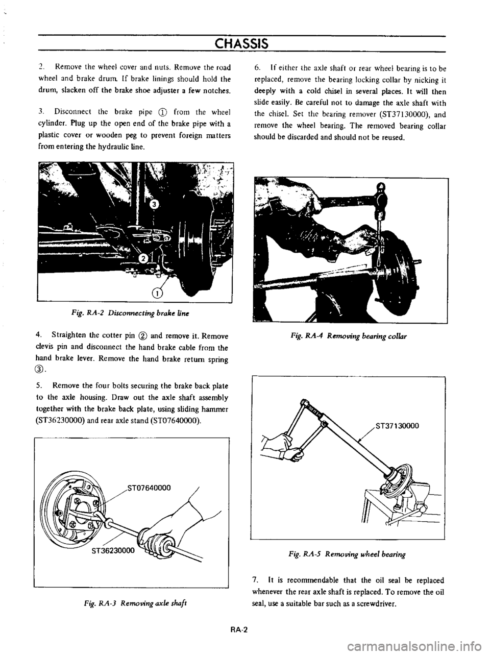
Vehicle
pulls
to
right
or
left
When
driving
with
hands
off
the
steering
wheel
over
a
flat
road
the
vehicle
gently
swerves
to
right
or
left
Note
A
defective
rear
suspension
may
also
be
the
cause
of
this
trouble
and
therefore
see
also
the
chapter
dealing
with
the
rear
suspension
Instability
of
vehicle
Stiff
steering
wheel
checking
up
procedure
Jack
up
front
wheels
detach
the
steering
gear
and
operate
the
steering
wheel
and
If
it
is
light
check
steering
linkage
and
suspension
groups
If
it
is
heavy
check
steering
gear
and
steering
colunm
groups
CHASSIS
Malfunction
of
shock
absorber
inside
the
strut
or
loose
installation
bolts
Unbalance
of
vehicle
level
Improper
air
pressure
of
tire
or
insuf
ficient
tightening
of
wheel
nuts
Difference
in
height
of
right
and
left
tire
treads
Incorrect
adjustment
or
abrasion
of
front
wheel
bearing
Collapsed
or
twisted
front
spring
Incorrect
wheel
alignment
Incorrect
brake
adjustment
binding
Worn
rubber
bushings
for
transverse
link
and
tension
rod
Deformed
steering
linkage
and
suspension
link
Unbalanced
vehicle
level
Improper
air
pressure
of
tire
Worn
rubber
bushings
for
transverse
link
and
tension
rod
Incorrect
wheel
alignment
Worn
or
deformed
steering
linkage
and
suspension
link
Incorrect
adjustment
of
steering
gear
Deformed
unbalanced
wheel
Improper
air
pressure
of
tire
Insufficient
lubricants
or
mixing
im
purities
in
steering
linkage
or
excessively
worn
steering
linkage
Stiff
or
damaged
suspension
ball
joint
or
lack
of
grease
Worn
or
incorrectly
adjusted
wheel
bearing
Worn
damaged
steering
gear
and
bearing
FA
26
Replace
or
retighten
Correct
the
unbalance
Adjust
or
tighten
Replace
tires
Adjust
or
replace
Replace
Adjust
Adjust
Replace
Replace
Correct
the
unbalance
Adjust
Adjust
Adjust
Replace
Adjust
Correct
or
replace
Adjust
Repl
nish
grease
or
re
place
the
part
Replace
Replace
or
adjust
Replace
Page 114 of 513
CHASSIS
Jumping
of
disc
wheel
Improper
air
pressure
of
tire
Adjust
Unbalanced
wheels
Adjust
Defective
shock
absorber
Replace
Defective
tire
Replace
Deformed
wheel
rim
Replace
Excessively
or
partially
worn
tire
Improper
air
pressure
of
tire
Adjust
Incorrect
wheel
alignment
Adjust
Defective
wheel
bearing
Replace
Incorrect
brake
adjustment
Adjust
Improper
tire
shifting
rotation
Adjust
Rough
and
improper
driving
manner
Drive
more
gently
SERVICE
JOURNAL
OR
BULLETIN
REFERENCE
DATE
JOURNAL
or
BULLETIN
No
PAGE
No
SUBJECT
FA
28
Page 116 of 513
REAR
AXLE
REAR
SUSPENSION
REAR
AXLE
CONTENTS
DESCRIPTION
REAR
AXLE
SHAFTS
Removal
RA
1
RA
l
RA
l
8
Inspection
Assembly
RA
3
RA
3
1
Axle
shaft
2
Spacer
3
Wheel
bearing
4
Wheel
bearing
collar
5
Oil
seal
6
Bearing
adjust
shim
7
Axle
case
8
Brake
drum
DESCRIPTION
Fig
RA
l
Sectional
view
of
rear
axle
The
rear
axle
is
of
a
semi
floating
type
The
axle
housing
is
a
press
steel
Banjo
type
housing
It
is
light
in
weight
and
is
sufficiently
strong
to
withstand
all
torsional
and
bending
loads
The
rear
wheel
bearings
are
of
presea1ed
types
There
fore
no
frequent
lubricating
service
is
required
However
when
the
rear
axle
is
disassembled
the
wheel
bearings
should
be
packed
with
an
approved
grease
prior
io
the
reinstallation
being
careful
not
to
damage
the
sealing
rubber
REAR
AXLE
SHAFTS
Removal
Apply
wheel
chocks
on
front
wheels
jack
up
the
rear
of
the
vehicle
and
support
it
on
stands
RA
l
Page 117 of 513

CHASSIS
2
Remove
the
wheel
cover
and
nuts
Remove
the
road
wheel
and
b
rake
drum
If
brake
linings
should
hold
the
drum
slacken
off
the
brake
shoe
adjuster
a
few
notches
3
Disconnect
the
brake
pipe
CD
from
the
wheel
cylinder
Plug
up
the
open
end
of
the
brake
pipe
with
a
plastic
cover
or
wooden
peg
to
prevent
foreign
matters
from
entering
the
hydraulic
line
Fig
RA
2
Disconnecting
brake
Une
4
Straighten
the
cotler
pin
@
and
remove
it
Remove
clevis
pin
and
disconnect
the
hand
brake
cable
from
the
hand
brake
lever
Remove
the
hand
brake
return
spring
CID
5
Remove
the
four
bolts
securing
the
brake
back
plate
to
the
axle
housing
Draw
out
the
axle
shaft
assembly
together
with
the
brake
back
plate
using
sliding
hammer
ST36230000
and
rear
axle
stand
ST07640000
ST07640000
I
Fig
RA
3
Removing
axle
shaft
6
If
either
the
axle
shaft
or
rear
wheel
bearing
is
to
be
replaced
remove
the
bearing
locking
collar
by
nicking
it
deeply
with
a
cold
chisel
in
several
places
It
will
then
slide
easily
Be
careful
not
to
damage
the
axle
shaft
with
the
chiscl
Set
the
bearing
remover
ST37130000
and
remove
the
wheel
bearing
The
removed
bearing
collar
should
be
discarded
and
should
not
be
reused
Fig
RA
4
Removing
bearing
collar
Fig
RA
5
Removing
wheel
bearing
7
It
is
recommendable
that
the
oil
seal
be
replaced
whenever
the
rear
axle
shaft
is
replaced
To
remove
the
oil
seal
use
a
suitable
bar
such
as
a
screwdriver
RA
2
Page 119 of 513
CHASSIS
4
Tighten
he
brake
back
plate
to
housing
nunge
bults
and
nuts
with
a
torque
of
1
5
to
2
0
kg
m
10
8
to
145
ft
Ibl
Check
the
rear
axle
shaft
end
playas
shown
in
Figure
RA
9
The
end
plav
should
be
less
than
U
I
nun
0
0039
in
Fig
RA
9
Checking
axle
shaft
end
play
REAR
SUSPENSION
CONTENTS
DESCRIPTION
REAR
SPRING
Removal
I
nspection
and
repair
RA
5
RA
5
RA
5
RA
5
I
n5tallatlon
REAR
SHOCK
ABSORBER
Replacement
Inspection
RA
6
RA
6
RA
6
RA
6
0
tr
1
1
@
5
@
7
I
Leaf
spring
5
Axle
case
8
Hand
brake
wire
2
Front
mounting
6
Gear
carrier
9
Brake
hose
3
Shackle
7
Torque
arrester
10
Bound
bumper
4
Shock
absorber
Fig
RA
10
Rear
suspension
RA
4