1973 DATSUN B110 brake
[x] Cancel search: brakePage 124 of 513
r
jWW
5
jJ
S
L
l
J
J
DATSUN
1200
MODEL
8110
SERIES
I
NISSAN
I
NISSAN
MOTOR
CO
LTD
TOKYO
JAPAN
SECTION
BR
BRAKE
BRAKE
SERVICE
DATA
AND
SPECIFICATIONS
TROUBLE
DIAGNOSES
AND
CORRECTIONS
BR
1
BR
23
BR
24
GI
Page 125 of 513
DESCRIPTION
BRAKE
PEDAL
Removal
Inspection
Reinstallation
TANDEM
MASTER
CYLINDER
Removal
Disassembly
Inspection
Reassembly
Reinstallation
SINGLE
MASTER
CYLINDER
Removal
and
disassembly
Inspection
Reassembly
and
reinstallation
BRAKE
LINE
Removal
Inspection
Reinstallation
Brake
line
pressure
differential
warning
light
switch
FRONT
DRUM
BRAKE
cr
I
1
0
I
I
CD
BRAKE
BRAKE
CONTENTS
BR
2
BR
2
BR
2
BR
2
BR
2
BR
3
BR
3
BR
3
BR
3
BR
4
BR
4
BR
4
BR
5
BR
5
BR
5
BR
5
BR
5
BR
6
BR
6
BR
7
BR
8
Removal
and
disassembly
Inspection
Reassembly
and
reinstallation
FRONT
DISC
BRAKE
Brake
pad
Caliper
assembly
Reassembly
Reinstallation
REAR
BRAKE
Removal
and
disassembly
Inspection
Reassembly
and
reinstallation
HAND
8RAKE
Removal
Inspection
Reinstallation
ADJUSTMENT
Brake
shoe
clearance
Brake
pedal
height
Hand
brake
Bleeding
hydraulic
system
@
7
o
i
1
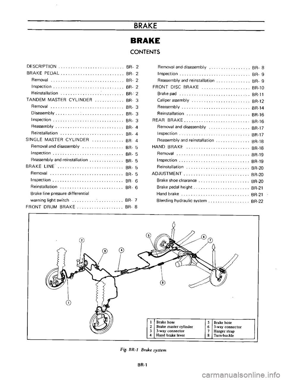
Brake
hose
2
Brake
master
cylinder
3
3
way
connector
4
Hand
brake
lever
5
Brake
hose
6
3
way
connector
7
Hanger
strap
8
Turn
buckle
Fig
BR
l
Brake
system
BR
BR
8
BR
9
BR
9
BR
lO
BR
Il
BR
12
BR
14
BR
16
BR
16
BR
17
BR
17
BR
18
BR
18
BR
19
BR
19
BR
20
BR
20
BR
20
BR
21
BR
21
BR
22
Page 126 of 513
CHASSIS
DESCRIPTION
The
Datsun
1200
series
new
models
adopt
a
hydraulic
brake
Dis
brake
or
two
leading
shoe
type
drum
brake
is
used
for
the
front
wheels
and
leading
trailing
shoe
type
drum
brake
is
used
for
the
rear
wheels
With
adoption
of
the
disc
brake
safety
at
high
speed
range
driving
is
further
improved
For
the
master
cylinder
either
single
type
or
tandem
type
is
used
There
are
two
types
of
tandem
type
master
cylinder
one
is
for
disc
brake
and
the
other
for
drum
brake
Under
the
standard
specifications
h0wever
the
tandem
type
master
cylinder
is
used
for
disc
brake
and
single
type
is
used
for
drum
brake
The
tandem
master
cylinder
provides
a
dual
brake
system
improving
safety
The
hand
brake
is
of
a
mechanical
type
which
brakes
the
rear
wheels
through
the
control
lever
and
steel
wire
The
control
lever
is
located
between
the
driver
and
assistant
seats
and
can
be
operated
easily
BRAKE
PEDAL
The
steering
colunm
bracket
supports
the
brake
pedaL
The
brake
pedal
is
instaUed
on
the
steering
column
bracket
with
a
fulcrum
pin
The
brake
pedal
arm
and
brake
master
cylinder
push
rod
are
joined
with
a
clevis
pin
The
stop
lamp
switch
opposes
the
brake
pedal
arm
bracket
and
operates
as
the
pedal
arm
moves
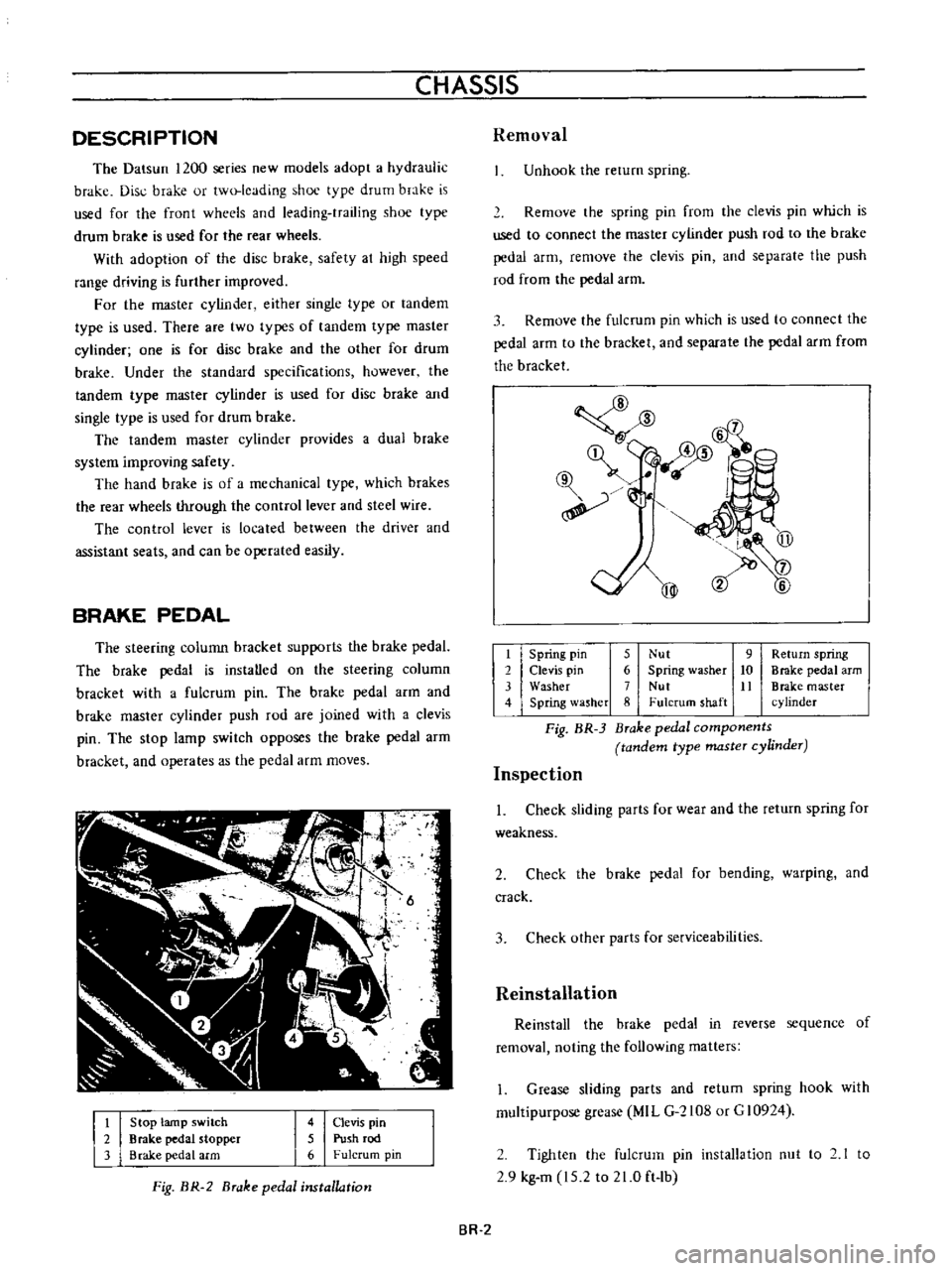
t
2
3
Stop
lamp
switch
Brake
pedal
stopper
Brake
pedal
arm
4
Clevis
pin
5
Push
rod
6
Fulcrum
pin
Fig
BR
2
Brake
pedal
installation
Removal
Unhook
the
rerum
spring
Remove
the
spring
pin
from
the
clevis
pin
which
is
used
to
connect
the
master
cylinder
push
rod
to
the
brake
pedal
arm
remove
the
clevis
pin
and
separate
the
push
rod
from
the
pedal
arm
3
Remove
the
fulcrum
pin
which
is
used
to
connect
the
pedal
arm
to
the
bracket
and
separate
the
pedal
arm
from
the
bracket
@
mm
l6
qf
@
@
t
Spring
pin
5
Nut
9
Return
spring
2
Clevis
pin
6
Spring
washer
10
Brake
pedal
arm
3
Washer
7
Nut
It
Brake
master
4
Spring
lasher
8
Fulcrum
shaft
cylinder
Fig
BR
3
Brake
pedal
components
tandem
type
master
cylinder
Inspection
1
Check
sliding
parts
for
wear
and
the
return
spring
for
weakness
2
Check
the
brake
pedal
for
bending
warping
and
crack
3
Check
other
parts
for
serviceabilities
Reinstallation
Reinstall
the
brake
pedal
in
reverse
sequence
of
removal
noting
the
following
matters
1
Grease
sliding
parts
and
retum
spring
hook
with
multipurpose
grease
MIL
G
2108
or
G
10924
2
Tighten
the
fulcrum
pin
installation
nut
to
2
1
to
2
9
kg
m
15
2
to
21
0
ft
lb
BR
2
Page 127 of 513
BRAKE
TANDEM
MASTER
CYLINDER
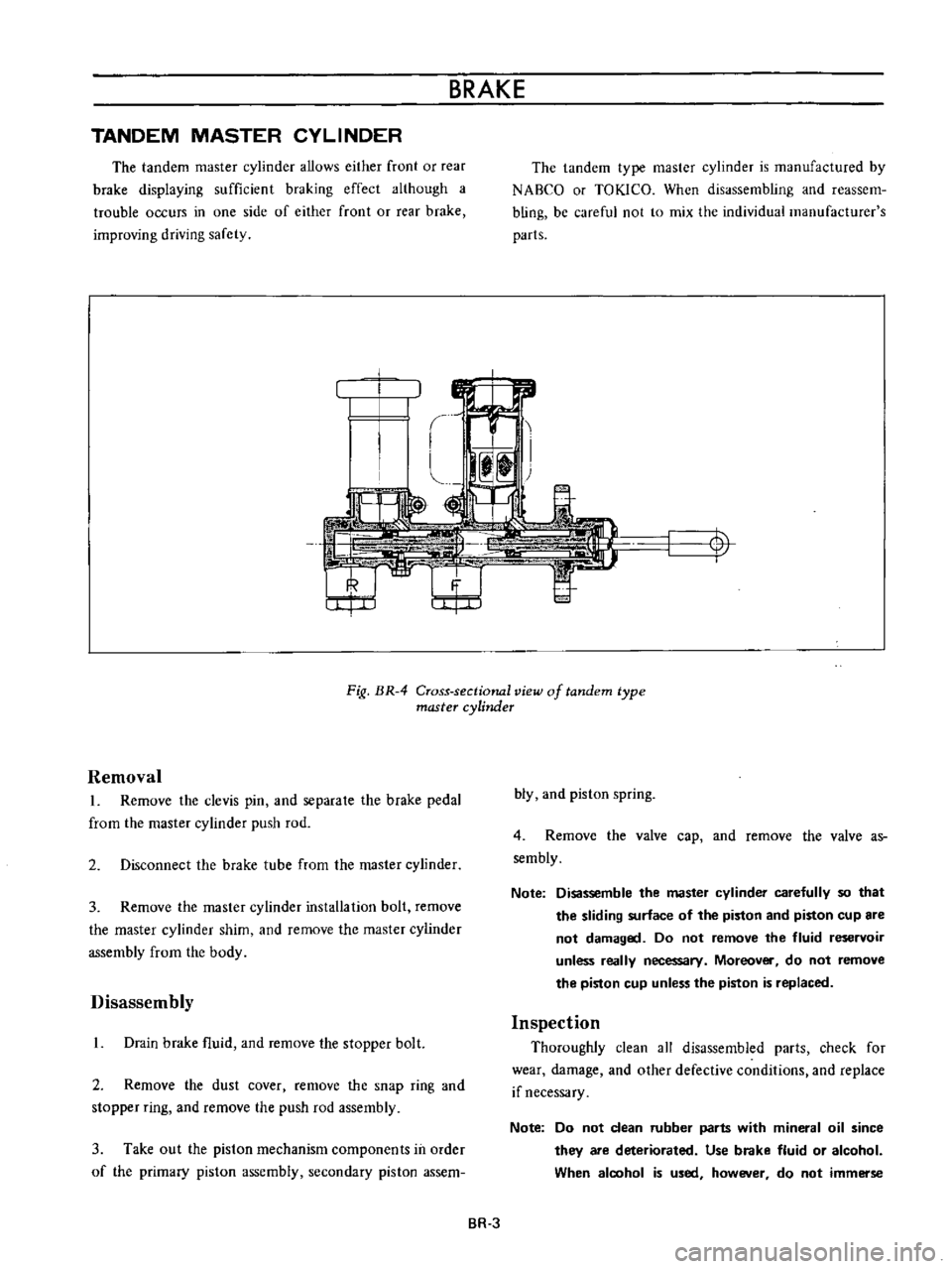
The
tandem
master
cylinder
allows
either
front
or
rear
brake
displaying
sufficient
braking
effect
although
a
trouble
occurs
in
one
side
of
either
front
or
rear
brake
improving
driving
safety
The
tandem
type
master
cylinder
is
manufactured
by
NABCO
or
TOKlCO
When
disassembling
and
reassem
bling
be
careful
not
to
mix
the
individual
manufacturer
s
parts
t
I
Fig
BR
4
Cross
sectional
view
of
tandem
type
master
cylinder
Removal
L
Remove
the
clevis
pin
and
separale
the
brake
pedal
from
the
master
cylinder
push
rod
2
Disconnect
the
brake
tube
from
the
master
cylinder
3
Remove
the
master
cylinder
installation
bolt
remove
the
master
cylinder
shim
and
remove
the
master
cylinder
assembly
from
the
body
Disassembly
L
Drain
brake
fluid
and
remove
the
stopper
bolt
2
Remove
the
dust
cover
remove
the
snap
ring
and
stopper
ring
and
remove
the
push
rod
assembly
3
Take
out
the
piston
mechanism
components
in
order
of
the
primary
piston
assembly
secondary
piston
assem
bly
and
piston
spring
4
Remove
the
valve
cap
and
remove
the
valve
as
sembly
Note
Disassemble
the
master
cylinder
carefully
so
that
the
sliding
surface
of
the
piston
and
piston
cup
are
not
damaged
Do
not
remove
the
fluid
reservoir
unless
really
necessary
Moreover
do
not
remove
the
piston
cup
unless
the
piston
is
replaced
Inspection
Thoroughly
clean
all
disassembled
parts
check
for
wear
damage
and
other
defective
conditions
and
replace
if
necessary
Note
Do
not
clean
rubber
parts
with
mineral
oil
since
they
are
deteriorated
Use
brake
fluid
or
alcohol
When
aloohol
is
used
however
do
not
immerse
BR
3
Page 128 of 513
CHASSIS
Ii
t
L
1
J
rJ
I
e
i
L
rubber
parts
und
alcohol
long
than
30
seconds
After
the
parts
are
cleaned
dry
them
with
com
pressed
air
Check
the
cylinder
and
piston
for
damage
and
uneven
wear
on
the
sliding
surface
and
for
other
defective
conditions
Replace
as
required
2
Replace
if
the
cylinder
and
piston
clearance
is
more
than
0
15
mm
0
006
in
3
In
principle
replace
the
piston
cup
packing
and
valves
with
new
ones
whenever
the
master
cylinder
is
disassembled
Be
sure
to
replace
if
damaged
worn
weakened
or
expanded
4
Check
the
return
springs
for
wear
damage
and
other
defective
conditions
and
replace
as
required
5
Replace
others
if
deformed
damaged
or
defective
Reassembly
Assemble
the
master
cylinder
in
reverse
sequence
of
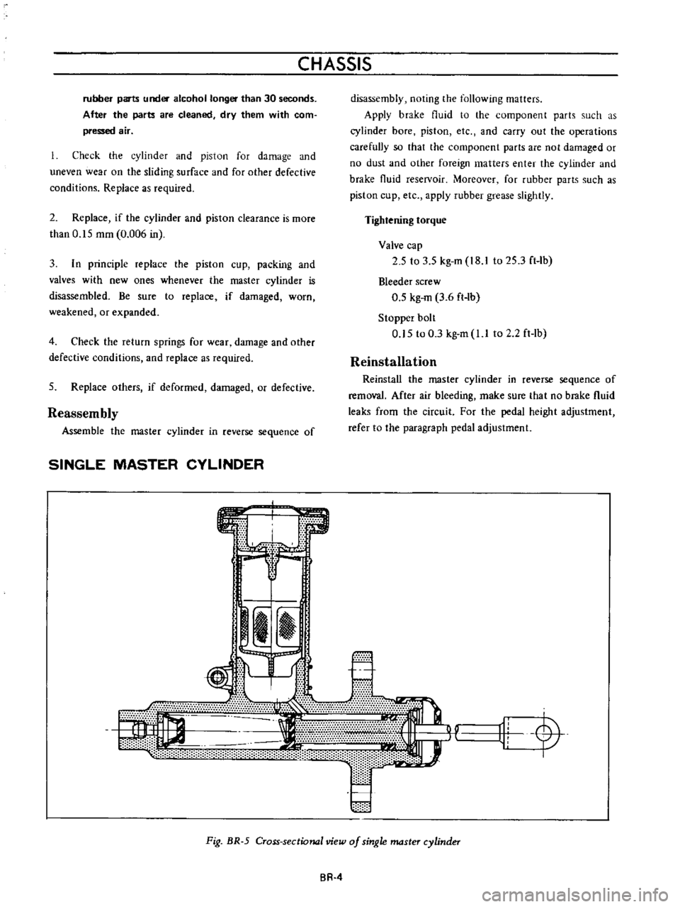
SINGLE
MASTER
CYLINDER
s
m
e
disassembly
noting
the
following
matters
Apply
brake
fluid
to
the
component
parts
such
as
cylinder
bore
piston
etc
and
carry
out
the
operations
carefully
so
that
the
component
parts
are
not
damaged
or
no
dust
and
other
foreign
matters
enter
the
cylinder
and
brake
fluid
reselVoir
Moreover
for
rubber
parts
such
as
piston
cup
etc
apply
rubber
grease
slightly
Tightening
torque
Valve
cap
2
5
to
3
5
kg
m
I8
to
25
3
ft
Ib
Bleeder
screw
0
5
kg
m
3
6
ft
lb
Stopper
bolt
0
5
to
0
3
kg
m
l
I
to
2
2ft
lb
Reinstallation
Reinstall
the
master
cylinder
in
reverse
sequence
of
removal
After
air
bleeding
make
sure
that
no
brake
fluid
leaks
from
the
circuit
For
the
pedal
height
adjustment
refer
to
lhe
paragraph
pedal
adjustment
r
11L
y
Fig
BR
5
Cross
sectional
view
of
single
master
cylinder
BR
4
Page 129 of 513
Removal
and
disassembly
The
single
master
cylinder
is
removed
and
disassembled
in
the
same
manner
as
the
tandem
type
master
cylinder
Inspection
Refer
to
the
section
covering
Inspection
of
tandem
type
master
cylinder
Reassembly
and
reinstallation
The
single
master
cylinder
is
reassembled
and
re
BRAKE
installed
in
the
same
manner
as
the
tandem
type
master
cylinder
BRAKE
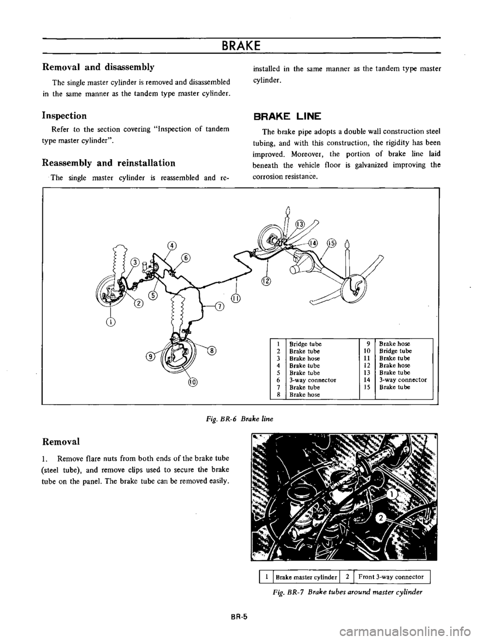
LINE
The
bl1lke
pipe
adopts
a
double
wall
construction
steel
tubing
and
with
this
construction
lhe
rigidily
has
been
improved
Moreover
the
portion
of
brake
line
laid
beneath
the
vehicle
floor
is
galvanized
improving
the
corrosion
resistance
1
Bridge
tube
9
Brake
hose
2
Brake
tube
10
Bridge
tube
3
Brake
hose
11
Brake
tube
4
Brake
tube
12
Brake
hose
5
Brake
tube
13
Brake
tube
10
6
3
way
connector
14
3
way
connector
7
Brake
tube
15
Brake
tu
be
8
Brake
hose
Fig
BR
6
Brake
line
Removal
1
Remove
flare
nuts
from
both
ends
of
the
brake
tube
steel
tube
and
remove
clips
used
to
secure
the
brake
tube
on
the
paneL
The
brake
tube
can
be
removed
easily
I
1
I
Brake
master
cylinder
I
2
Front
3
way
connector
Fig
BR
7
Brake
tubes
around
master
cylinder
BR
5
Page 130 of 513
CHASSIS
1
I
Front
3
way
connector
I
2
I
Brake
master
cylinder
I
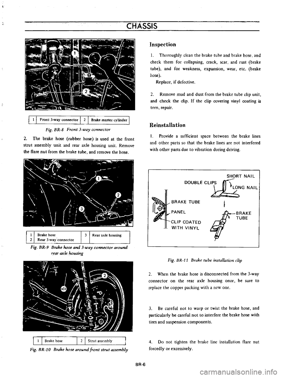
Fig
BR
8
Front
3
way
connector
2
The
brake
hose
rubber
hose
is
used
at
the
front
strut
assembly
unit
and
fear
axle
housing
unit
Remove
the
flare
nut
from
the
brake
tube
and
remove
the
hose
I
r
I
I
l
j
u
l
I
J
II
V
r
1
0
l
I
l
I
I
Brake
hose
I
3
I
Rear
axle
hOUSing
2
Rear
3
way
connector
Fig
BR
9
Brake
hose
and
3
way
connector
around
rear
ax
Ie
housi
g
1
1
Brake
hose
I
2
I
Strut
assembly
Fig
BR
J
0
Brake
hose
around
front
strut
assembly
Inspection
L
Thoroughly
clean
the
brake
tube
and
brake
hose
and
check
them
for
collapsing
crack
scar
and
rust
brake
tube
and
for
weakness
expansion
wear
etc
brake
hose
Replace
if
defective
2
Remove
mud
and
dust
from
the
brake
tube
clip
unit
and
check
the
clip
If
the
clip
covering
vinyl
coating
is
torn
repair
Reinstallation
1
Provide
a
sufficient
space
between
the
brake
lines
and
other
parts
so
that
the
brake
lines
are
not
interfered
with
other
parts
due
to
vibration
during
driving
SHORT
NAIL
DOUBLECLI
S
t
LONG
NAI
L
BRAKE
TUBE
PANEL
CLIP
COATED
WITH
VINYL
BRAKE
TUBE
Fig
BR
l1
Brake
tube
installation
clip
2
When
the
brake
hose
is
disconnected
from
the
3
way
connector
on
the
rear
axle
housing
once
be
sure
to
replace
the
copper
packing
with
a
new
one
3
Be
careful
not
to
warp
or
twist
the
brake
hose
and
particularly
be
careful
not
to
interfere
the
brake
hose
with
tires
and
suspension
components
4
Do
not
tighten
the
brake
line
installation
flare
nut
forcedly
or
excessively
BR
6
Page 131 of 513

Tightening
torque
3
way
connector
1
5
to
1
8
kg
m
10
8
to
13
0
ft
lh
1
5
to
1
8
kg
m
10
8
to
13
0
ft
lh
1
5
to
1
8
kg
m
10
8
to
13
0
ft
lb
0
7
to
0
9
kg
m
5
1
to
6
5
ft
1b
Master
cylinder
Brake
hose
Air
bleeder
5
Fill
the
master
cylinder
brake
fluid
reservoir
with
brake
fluid
and
perform
air
bleeding
complele1y
Note
a
Do
not
use
brake
fluid
other
than
specified
b
The
specified
brake
fluid
is
used
for
both
single
and
tandem
type
master
cylinders
6
Upon
completion
of
air
bleeding
make
sure
that
the
brake
operates
correctly
and
check
the
brake
tube
and
hose
connectors
for
fluid
leaking
Fully
depress
the
brake
pedal
continue
to
depress
the
brake
pedal
for
several
seconds
and
make
sure
that
no
brake
fluid
leaks
from
any
part
of
the
brake
line
Replace
defective
part
if
required
Brake
line
pressure
differential
warning
light
switch
A
warning
light
is
located
on
the
instrument
panel
to
warn
the
driver
when
a
pressure
difference
of
13
to
17
kg
cm2
185
to
2421bJsq
in
exists
between
the
front
and
rear
b
rake
systems
A
hydraulically
actuated
warning
light
switch
is
located
in
the
engine
compartment
Both
front
and
rear
brake
systems
are
connected
to
this
switch
assembly
When
a
pressure
difference
of
13
to
17
kgJcm2
185
to
242
lbJsq
in
occurs
between
the
front
and
rear
brake
systems
the
valves
will
shuttle
toward
the
side
with
the
low
pressure
The
valve
contacts
with
the
switch
terminal
BRAKE
the
ground
circuit
for
the
warning
light
is
completed
and
thus
the
warning
light
lights
In
this
case
correct
the
hydraulic
brake
problem
and
bleed
the
brakes
Check
the
warning
light
switch
assembly
for
a
proper
operation
Check
the
switch
assembly
for
fluid
leakage
Note
Do
not
attempt
to
repair
switch
for
any
reason
replace
switch
assembly
completely
1
To
front
brake
L
H
2
From
master
cylinder
F
3
From
master
cylinder
R
4
To
rear
brake
L
B
R
M
5
To
front
brake
R
H
Fig
BR
12
Warning
light
switch
r
I
@
I
I
3
I
Valve
assembly
4
Piston
load
spring
Wire
terminal
Brake
tube
Fig
BR
13
Sectional
view
of
warning
light
switch
BR
7