1973 DATSUN B110 brake
[x] Cancel search: brakePage 178 of 513
CHASSIS
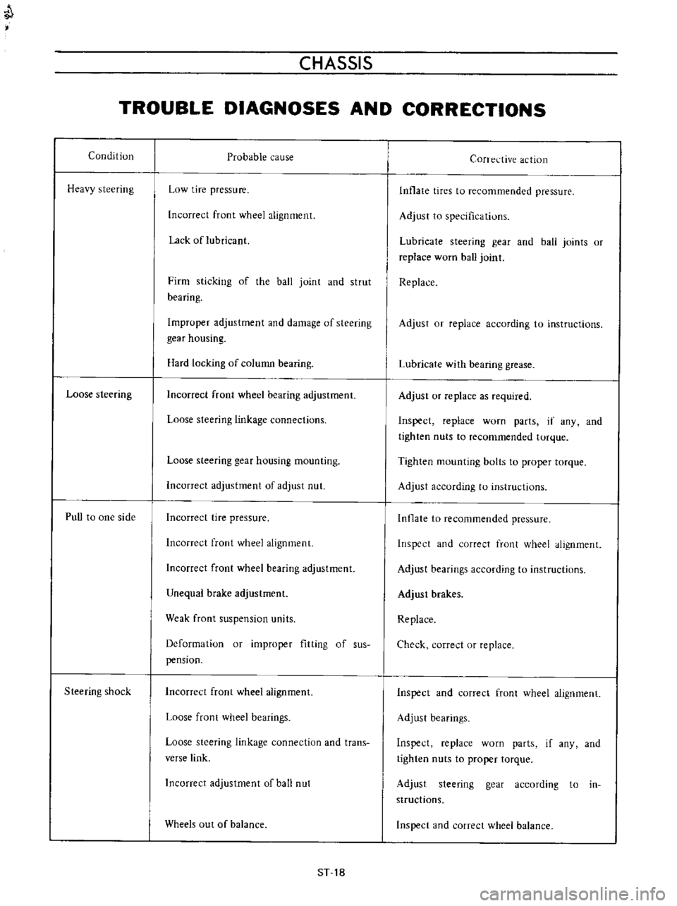
TROUBLE
DIAGNOSES
AND
CORRECTIONS
Condition
Heavy
steering
Loose
steering
PuU
to
one
side
Steering
shock
Probable
cause
Low
tire
pressure
Incorrect
front
wheel
alignment
Lack
of
lubricant
Firm
sticking
of
the
ball
joint
and
strut
bearing
Improper
adjustment
and
damage
of
steering
gear
housing
Hard
locking
of
column
bearing
Incorrect
front
wheel
bearing
adjustment
Loose
steering
linkage
connections
Loose
steering
gear
housing
mounting
Incorrect
adjustment
of
adjust
nut
Incorrect
tire
pressure
Incorrect
front
wheel
alignment
Incorrect
front
wheel
bearing
adjustment
Unequal
brake
adjustment
Weak
front
suspension
units
Deformation
or
improper
fitting
of
sus
pension
Incorrect
front
wheel
alignment
Loose
front
wheel
bearings
Loose
steering
linkage
connection
and
trans
verse
link
Incorrect
adjustment
of
ball
nut
Wheels
out
of
balance
ST
18
Corrective
action
Inflate
tires
to
recommended
pressure
Adjust
to
specifications
Lubricate
steering
gear
and
ball
joints
or
replace
worn
ball
joint
Replace
Adjust
or
replace
according
to
instructions
Lubricate
with
bearing
grease
Adjust
or
replace
as
required
Inspect
replace
worn
parts
if
any
and
tighten
nuts
to
recommended
torque
Tighten
mounting
bolts
to
proper
torque
Adjust
according
to
instructions
Inflate
to
recommended
pressure
Inspect
and
correct
front
wheel
alignment
Adjust
bearings
according
to
instructions
Adjust
brakes
Replace
Check
correct
or
replace
Inspect
and
correct
front
wheel
alignment
Adjust
bearings
Inspect
replace
worn
parts
if
any
and
tighten
nuts
to
proper
torque
Adjust
steering
gear
according
to
in
structions
Inspect
and
correct
wheel
balance
Page 208 of 513

BODY
Fig
BF
29
Removing
front
fender
II
FRONT
BUMPER
Remove
six
bolts
retaining
bumper
stay
to
body
and
remove
the
front
bumper
from
the
body
together
with
the
bumper
stay
RADIATOR
GRILLE
Loosen
self
tapping
screws
five
self
tapping
screws
for
sedan
station
wagon
and
van
and
ten
for
coupe
and
remove
the
radiator
grille
frorn
the
body
The
radiator
grille
for
coupe
is
made
of
ABS
resin
Be
careful
not
to
allow
brake
fluid
or
oil
slicking
to
it
7
7f
rl4
o
j
j
iiA
i
DIATIJR
GR
L
SEt
SC
8N
S
i
e
t
II
L
T
RADIATOR
GRill
SET
SCREWS
Fig
BF
30
Removing
radiator
grille
Coupe
OUTSIDE
MIRROR
Indicates
outside
mirror
installing
positions
liMA
t
o
e
O
I
I
Dimen
sIons
Item
A
B
c
D
E
27
to
6
to
Round
shape
817
29
5
25
27
8
dia
6
2
dia
movable
32
2
1
161
0
98431
1
063
to
0
2362
te
mirror
1
094
0
2441
6
to
Round
shape
817
35
40
9
dia
6
2
dia
mirror
32
2
1
378
l
575
0
3543
0
2362
to
0
2441
Unit
mm
in
Fig
BF
31
Fender
mirror
installing
positions
IW
36
l
71
Ta
h
Le
O
II
coo
c
l
2
f
4
5
358
17
77
74
7
Unit
mm
inl
Fig
RF
32
Door
mirror
installing
position
for
right
hand
drive
vehicle
SF
18
Page 228 of 513
@
c
@
CD
w
1
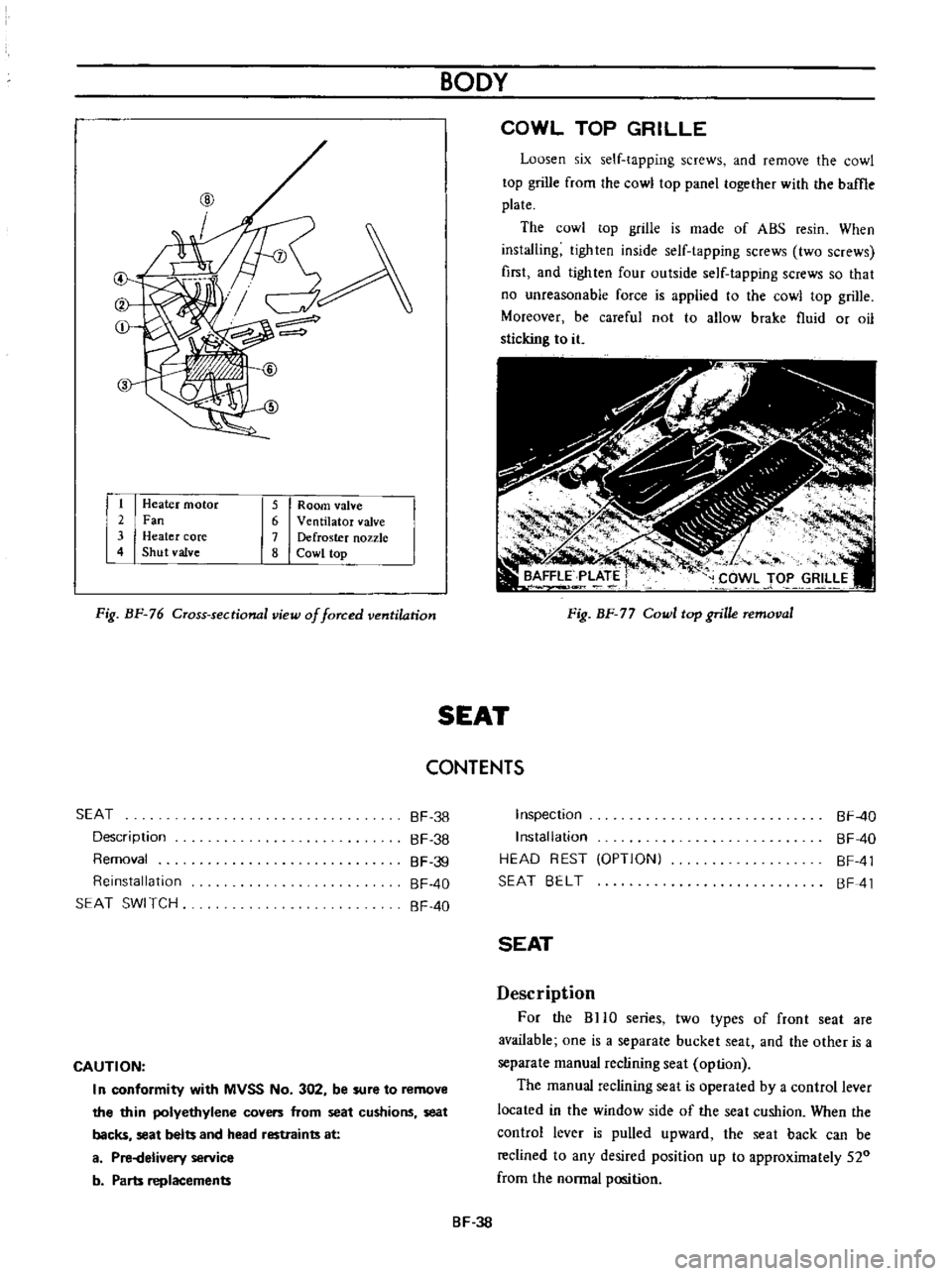
Heater
motor
2
Fan
3
Heater
core
4
Shut
valve
5
Room
valve
6
Ventilator
valve
7
Defroster
nozzle
8
Cowl
top
Fig
BF
76
Cross
sectional
view
of
forced
ventilation
BODY
COWL
TOP
GRILLE
Loosen
six
self
tapping
screws
and
remove
the
cowl
top
grille
from
the
cowl
top
panel
together
with
the
baffle
plate
The
cowl
top
grille
is
made
of
ABS
resin
When
installing
tighten
inside
self
tapping
screws
two
screws
first
and
lighten
four
outside
self
tapping
screws
so
that
no
unreasonable
force
is
applied
to
the
cowl
top
grille
Moreover
be
careful
not
to
allow
brake
fluid
or
oil
sticking
to
it
Fig
BF
77
Cowl
top
grille
removal
SEAT
CONTENTS
SEAT
Description
Removal
Reinstallation
SEAT
SWI
TCH
BF
38
BF
38
BF
39
BF
40
BF
40
CAUTION
I
n
conformity
with
MVSS
No
302
be
sure
to
remove
the
thin
polyethylene
covers
from
seat
cushions
seat
backs
seat
belts
and
head
restraints
at
a
Pi
Helivery
service
b
Parts
replacements
Inspection
Installation
HEAD
REST
OPTIONI
SEAT
BELT
BF
40
BF
40
BF
41
BF
41
SEAT
Description
For
the
BHO
series
two
types
of
front
seat
are
available
one
is
a
separate
bucket
seat
and
the
other
is
a
separate
manual
reclining
seat
option
The
manual
reclining
seat
is
operated
by
a
control
lever
located
in
the
window
side
of
the
seat
cushion
When
the
control
lever
is
pulled
upward
the
seat
back
can
be
reclined
to
any
desired
position
up
to
approximately
520
from
the
normal
position
BF
38
Page 245 of 513
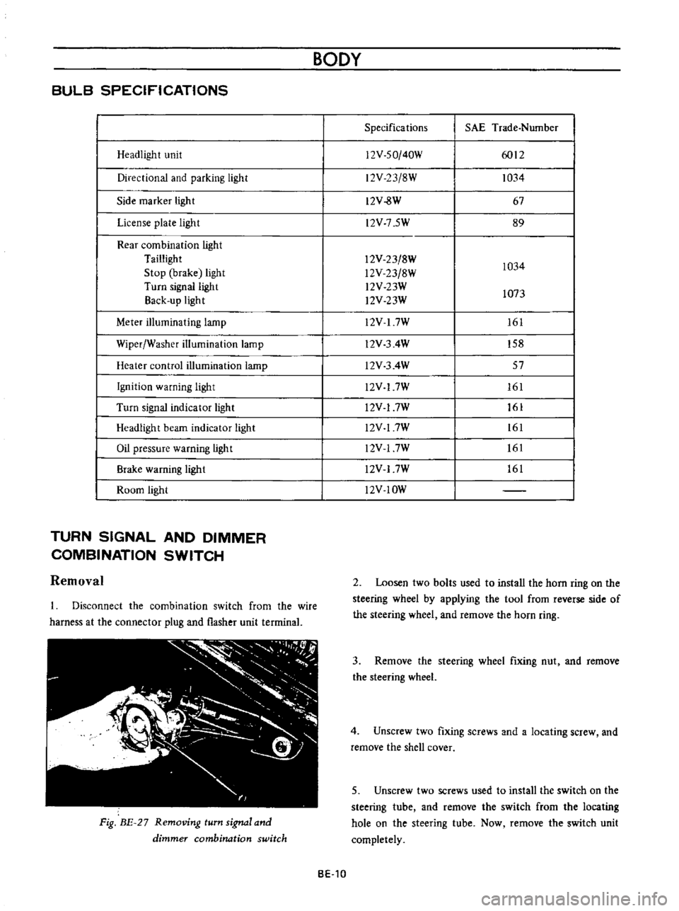
BULB
SPECIFICATIONS
Headlight
unit
Directional
and
parking
light
Side
marker
light
License
plate
light
Rear
combination
light
Taillight
Stop
brake
light
Turn
signal
light
Back
up
light
Meter
illuminating
lamp
Wiper
Washer
illumination
lamp
Heater
control
illumination
lamp
Ignition
warning
light
Turn
signal
indicator
light
Headlight
beam
indicator
light
Oil
pressure
warning
light
Brake
warning
ligh
t
Room
light
TURN
SIGNAL
AND
DIMMER
COMBINATION
SWITCH
Removal
Disconnect
the
combination
switch
from
the
wire
harness
at
the
connector
plug
and
flasher
unit
terrninal
Fig
BE
27
Removing
turn
signal
and
dimmer
combination
switch
BODY
Specifications
SAE
Trade
Number
12V
SO
40W
6012
12V
23
8W
1034
12V
8W
67
l2V
7
5W
89
12V
23
8W
1034
l2V
23
8W
l2V
23W
1073
l2V
23W
12V
I
7W
161
l2V
3
4W
158
l2V
3
4W
57
l2V
17W
161
l2V
17W
161
l2V
17W
161
l2V
17W
161
l2V
17W
161
l2V
IOW
2
Loosen
two
bolts
used
to
install
the
horn
ring
on
the
steering
wheel
by
applying
the
tool
from
reverse
side
of
the
steering
wheel
and
remove
the
horn
ring
3
Remove
the
steering
wheel
fixing
nut
and
remove
the
steering
wheel
4
Unscrew
two
fixing
screws
and
a
locating
screw
and
remove
the
shell
cover
5
Unscrew
two
screws
used
to
install
the
switch
on
the
steering
tube
and
remove
the
switch
from
the
locating
hole
on
the
steering
tube
Now
remove
the
switch
unit
completely
BE
10
Page 253 of 513

BODY
METERS
AND
GAUGES
CONTENTS
CLUSTER
LID
Oescri
ption
Removal
SPEEDOMETER
Replacement
FUEL
GAUGE
AND
TEMPERATURE
GAUGE
Description
Replacement
BE
1B
BE
18
BE
18
BE
19
BE
19
BE
19
BE
19
BE
20
CLUSTER
LID
Description
The
cluster
lid
holds
various
rneters
indicators
and
clock
located
around
the
speedorneter
Printed
circuit
board
is
used
at
the
back
of
the
meter
as
shown
in
Figure
BE
38
and
the
printed
circuit
board
is
connected
with
multiple
connectors
Thus
the
meters
Can
be
inspected
and
serviced
extremely
easily
Except
for
the
speed
ometer
all
rneters
are
operated
electrically
The
fuel
gauge
and
therrnometer
are
very
reliable
and
they
are
equipped
with
bimetal
devices
F
a
o
ill
I
1
a
a
Fig
BE
34
Combination
meters
Removal
Disconnect
the
battery
terminal
depressing
the
OIL
PRESSURE
AND
IGNITION
WARNING
LAMPS
HAND
BRAKE
WARNING
LAMP
BULB
SPECIFICATIONS
TROUBLE
DIAGNOSES
AND
CORRECTIONS
Speedometer
Thermometer
and
fuel
meter
Oil
pressure
and
ignition
warning
lamps
BE
20
BE
21
BE
21
BE
22
BE
22
BE
23
BE
25
windshield
wiper
switch
lighting
switch
and
choke
lever
knobs
turn
them
counterclockwise
to
remove
Remove
the
escutcheon
2
Inserting
your
hand
into
back
of
the
cluster
lid
disconnect
the
cigarette
lighter
cable
and
turn
and
remove
the
cigarette
lighter
outer
case
3
Remove
the
radio
and
heater
control
knobs
4
Remove
the
shell
cover
from
the
steering
tube
loosen
the
screws
used
to
secure
the
meter
housing
to
the
instrument
panel
and
remove
the
cluster
lid
5
Pull
out
the
l2
pole
round
shape
connector
and
remove
the
speedometer
cable
union
nut
6
Remove
the
cluster
lid
from
the
instrument
panel
Fig
BE
35
Removing
clllSter
jd
BE
18
Page 256 of 513

BODY
ElECTRICAL
When
the
ignition
switch
is
set
to
ON
the
ignition
wa
rning
circuit
is
closed
and
current
flows
flows
from
the
ignition
switch
to
the
warning
lamp
bulb
and
ground
through
the
regulator
When
the
engine
is
started
and
the
generator
comes
into
operation
the
generator
output
current
opposes
the
current
flowing
from
the
warning
lamp
in
effect
it
breaks
the
warning
circuit
ground
connection
and
the
lamp
goes
out
l
r
hffi
u
z
Ignition
switch
I
Q
6
I
0
c
M
1
E
8
ca
i
L
g
PI
lot
c
P
I
j
co
rt
0
relay
E
0
5
y
y
1
N
N
3
Alternator
Regulator
Fig
BE
41
Circuit
of
ignition
warning
system
HAND
BRAKE
WARNING
LAMP
This
lamp
functions
both
hand
brake
warning
larnp
and
BULB
SPECIFICATIONS
service
brake
line
pressure
differential
warning
lamp
When
a
difference
between
front
and
rear
brake
line
pressures
reaches
the
rated
range
13
to
17
kgfcm2
185
to
242
lb
sq
in
the
ground
circuit
for
the
warning
lamp
is
closed
and
the
warning
lamp
lights
IGNITION
SWITCH
WARNING
LAMP
L
E
WARNING
SWITCH
1
SERVICE
BRAKE
LINE
PRESSU
R
E
DIFFERENTIAL
WARNING
J
SWITCH
Fig
BE
42
Circuit
diagram
for
brake
warning
system
tern
Specifications
Square
type
meter
Round
type
meter
Meter
illumination
larnp
VoW
12
3
4
2
12
1
7
3
Turn
signal
pilot
lamp
VoW
12
3
4
2
12
1
7
2
Head
lamp
main
high
beam
VoW
12
3
4
I
12
17
1
pilot
lamp
Ignition
warning
lamp
VoW
123
4
I
12
17
1
Oil
pressure
warning
lamp
VoW
12
3
4
1
12
1
7
1
Hand
brake
warning
lamp
VoW
12
1
7
1
for
U
S
A
CANADA
Clock
illumination
lamp
VoW
123
4
I
12
17
2
Figure
encircled
in
parentheses
indicates
number
of
bulbs
used
BE
21
Page 291 of 513
ti
r
f
o
1
b
4
AI
I
W
n
t
i
i
1
i
f
f
7i
ii
y
0
r
1
J
1
t
I
r
I
DATSUN
1200
SERVICE
MANUAL
MODEL
8110
SERIES
N
I
NISSAN
MOTOR
CO
LTD
TOKYO
JAPAN
j
QUICK
REFERENCE
INDEX
GENERAL
INfORMATION
GI
EMISSION
CONTROL
AND
TUNE
UP
ET
ENGINE
MECHANICAL
EM
REAR
AXlE
8
REAR
SUSPENSiON
BRAKE
WHEEL
AND
TIRE
STEERING
ENGINE
CONTROL
fUEL
8
EXHAUST
BODY
BODY
ElECTRICAL
SERVICE
EQUIPMENT
Page 297 of 513
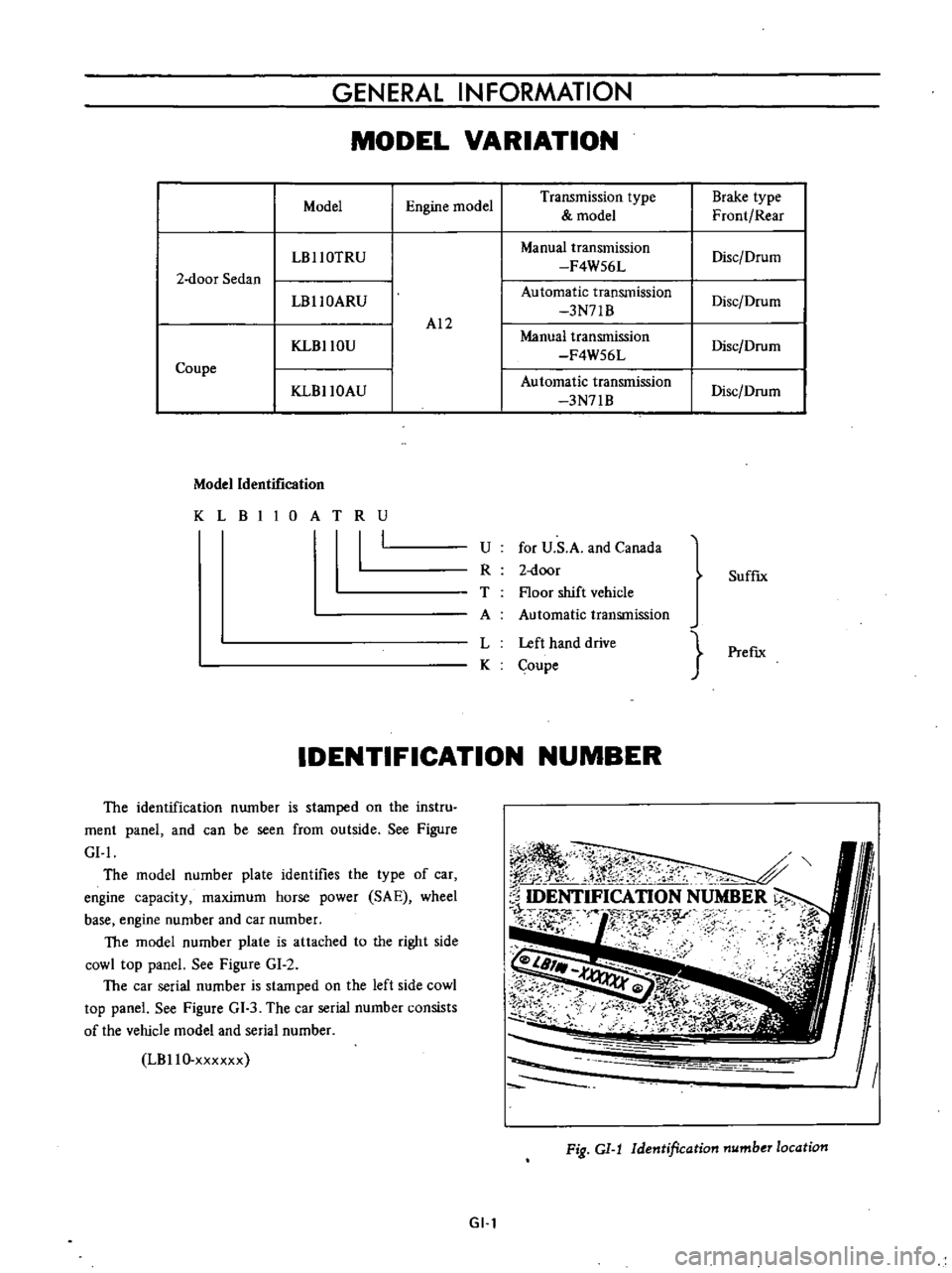
GENERAL
INFORMATION
MODEL
VARIATION
Model
Engine
model
Transmission
type
Brake
type
model
Front
Rear
LBllOTRU
Manual
transmission
Disc
Drum
F4W56L
2
door
Sedan
LBllOARU
Automatic
transmission
Disc
Drum
3N71B
AI2
KLBllOU
Manual
transmission
Disc
Drum
F4W56L
Coupe
Automatic
transmission
KLBllOAU
3N71B
Disc
Drum
Model
Identification
KLBIIOATRU
I
U
for
U
S
A
and
Canada
R
2
door
T
Floor
shift
vehicle
A
Automatic
transmission
L
Left
hand
drive
K
Coupe
SuffIx
PrefIx
IDENTIFICATION
NUMBER
The
identification
number
is
stamped
on
the
instru
ment
panel
and
can
be
seen
from
outside
See
Figure
GI
I
The
model
number
plate
identifles
the
type
of
car
engine
capacity
maximum
horse
power
SA
E
wheel
base
engine
number
and
car
number
The
model
number
plate
is
attached
to
the
right
side
cowl
top
panel
See
Figure
GI
2
The
car
serial
number
is
stamped
on
the
left
side
cowl
top
panel
See
Figure
GI
3
The
car
serial
number
consists
of
the
vehicle
model
and
serial
number
LBllO
xxxxxx
I
ll
r
N
t
0
S
k
j
c
ftr
o
l
l
r
2
0
IDENTIFICATION
NUMBER
l
r
f
N
s
r
F
i
u
I
Fig
GI
J
Identification
number
location
GI
l