1973 DATSUN B110 brake
[x] Cancel search: brakePage 302 of 513
GENERAL
INFORMATION
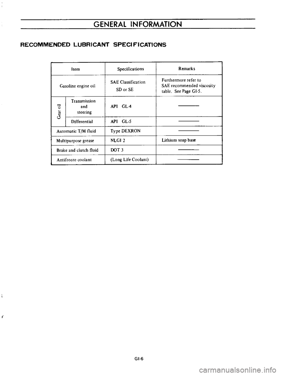
RECOMMENDED
LUBRICANT
SPECI
FICATIONS
Item
Gasoline
engine
oil
o
Transmission
and
steering
Differential
Automatic
TIM
fluid
Multipurpose
grease
Brake
and
clutch
fluid
Antifreeze
coolant
i
Specifications
SAE
Classification
SO
or
SE
API
G
L
4
API
GL
5
Type
DEXRON
NLGI2
DOT
3
Long
Life
Coolant
GI
6
Remarks
Furthermore
refer
to
SAE
recommended
viscosity
table
See
Page
GI
5
Lithium
soap
base
Page 313 of 513
ENGINE
Adjusting
carburetor
idle
rpm
mixture
ratio
Idle
mixture
adjustment
requires
the
use
of
a
CO
meter
When
preparing
to
adjust
idle
mixture
it
is
essential
to
have
the
meter
thoroughly
warmed
and
calibrated
Warm
up
the
engine
sufficiently
2
Continue
engine
operation
for
one
minute
under
idling
speed
3
Adjust
throttle
adjusting
screw
so
that
engine
speed
is
800
rpm
in
NO
position
for
automatic
transmission
4
Check
ignition
timing
if
necessary
adjust
it
to
the
specifications
Ignition
timing
SO
800
rpm
S
Adjust
idle
adjusting
screw
so
that
CO
percentage
is
1
5
t
O
S
6
Repeat
the
adjustments
as
described
in
steps
3
and
S
above
so
that
CO
percentage
is
I
i
t
O
S
at
800
rpm
Cautions
a
On
automatic
transmission
equipped
model
check
must
be
done
in
the
0
position
Be
sure
to
apply
parking
brake
and
to
lock
both
front
and
rear
wheels
with
wheel
chocks
b
Hold
brake
pedal
while
stepping
down
on
accelerator
pedal
Otherwise
car
will
rush
out
dangerously
7
On
automatic
transmission
equipped
model
make
sure
that
the
adjustment
has
been
made
with
the
selector
lever
in
N
position
And
then
check
the
specifications
with
the
lever
in
D
position
Insure
that
CO
percent
and
idle
speed
are
as
follows
Idle
rpm
CO
percentage
with
lever
in
D
position
6S0
I
S
t
O
S
If
necessary
adjust
by
progressively
turning
throttle
adjusting
screw
and
idle
adjusting
screw
until
correct
adjustments
are
made
Notes
a
Do
not
attempt
to
screw
down
the
idle
adjusting
screw
completely
to
avoid
damage
to
the
tip
which
will
tend
to
cause
malfunctions
b
After
idle
adjustment
has
been
made
shift
the
lever
to
N
or
p
position
for
automatic
transmission
c
Remove
wheel
chocks
before
starting
the
car
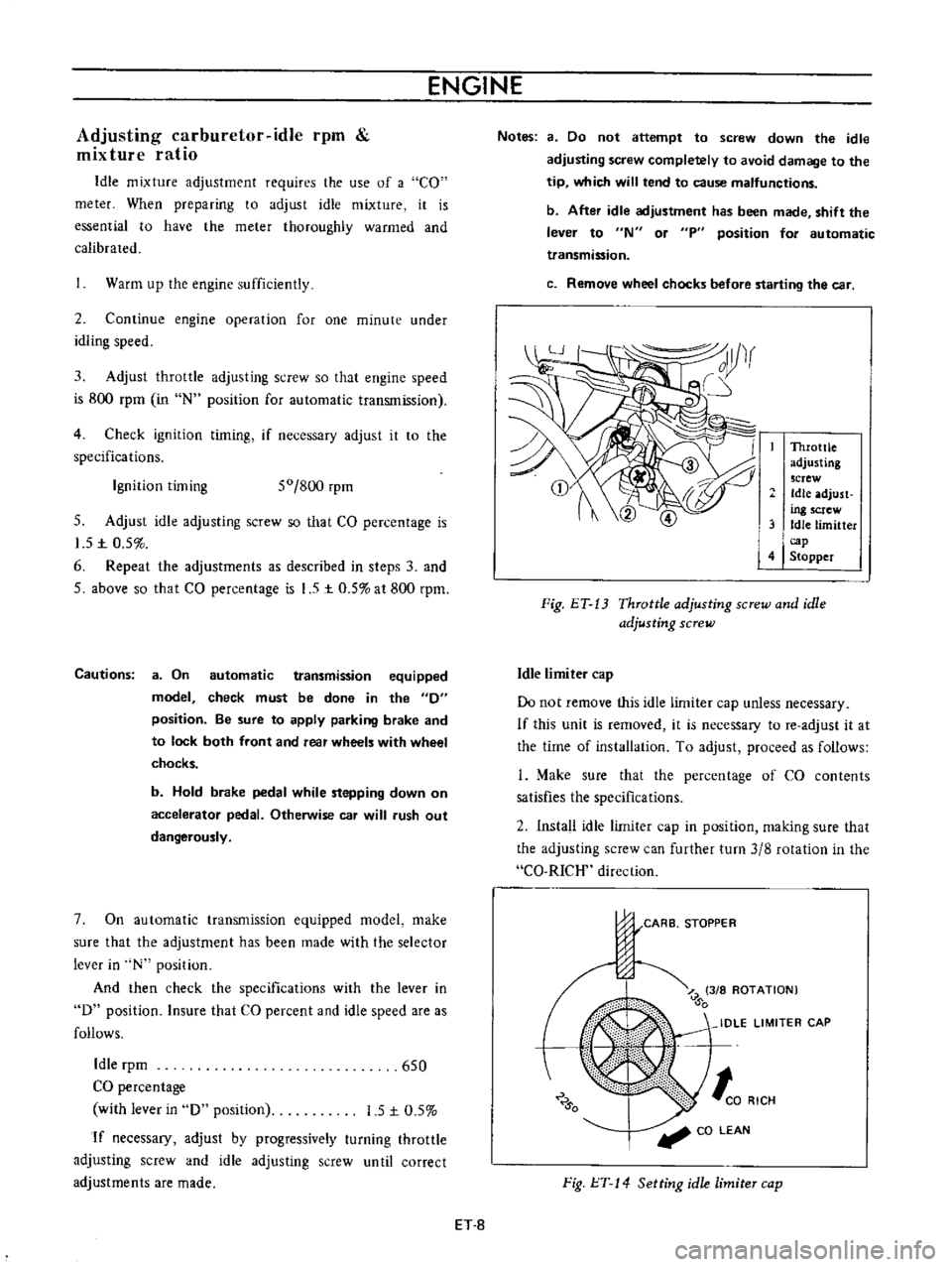
Throttle
adjusting
screw
Idle
adjust
ing
screw
3
Idle
limitter
cap
4
Stopper
Fig
ET
13
Throttle
adjusting
screw
and
idle
adjusting
screw
Idle
limiter
cap
Do
not
remove
this
idle
limiter
cap
unless
necessary
If
this
unit
is
removed
it
is
necessary
to
re
adjust
it
at
the
time
of
installation
To
adjust
proceed
as
follows
L
Make
sure
that
the
percentage
of
CO
contents
satisfies
the
specifications
2
Install
idle
limiter
cap
in
position
making
sure
that
the
adjusting
screw
can
further
turn
3
8
rotation
in
the
CO
RICH
direction
CARB
STOPPER
J
Z
3
8
ROTATION
0
IDLE
LIMITER
CAP
0
to
RICH
CO
LEAN
Fig
l
T
14
Setting
idle
limiter
cap
ET
8
Page 315 of 513
ENGINE
Replacing
fuel
filter
Check
for
a
contamination
element
water
deposit
and
defection
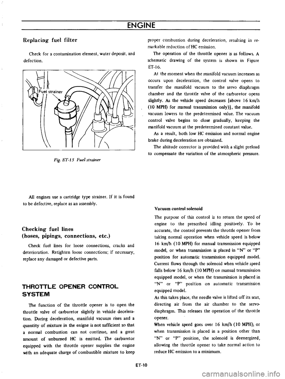
Fig
ET
15
Fuel
strcrineT
All
engines
use
a
cartridge
type
strainer
If
it
is
found
to
be
defective
replace
as
an
assembly
Checking
fuel
lines
hoses
pipings
connections
etc
Check
fuel
lines
for
loose
connections
cracks
and
deterioration
Retighten
loose
connections
if
necessary
replace
any
damaged
or
defective
parts
THROTTLE
OPENER
CONTROL
SYSTEM
The
function
of
the
throttle
opener
is
to
open
the
throttle
valve
of
carburetor
slightly
in
vehicle
decelera
tion
During
deceleration
manifold
vacuum
rises
and
a
quantity
of
mixture
in
the
enigne
is
not
sufficient
so
that
a
normal
combustion
can
not
continue
and
a
great
amount
of
unburned
HC
is
emitted
The
carburetor
equipped
with
the
throttle
opener
supplies
the
engine
with
an
adequate
charge
of
combustible
mixture
to
keep
proper
combustion
during
deceleration
resulting
in
re
markable
reduction
of
He
emission
The
operation
of
the
throttle
opener
is
as
follows
A
schematic
drawing
of
the
system
is
shown
in
Figure
ET
16
At
the
moment
when
the
manifold
vacuum
increases
as
occurs
upon
deceleration
the
control
valve
opens
to
transfer
the
manifold
vacuum
to
the
servo
diaphragm
chamber
and
the
throttle
valve
of
the
carburetor
opens
slightly
As
the
vehicle
speed
decreases
above
16
km
h
10
MPH
for
manual
transmission
only
the
manifold
vacuum
lowers
to
the
predetermined
value
The
vacuum
control
valve
begins
to
close
gradually
keeping
the
manifold
vacuum
at
the
predetermined
constant
value
As
a
result
both
low
HC
emission
and
normal
engine
brake
during
deceleration
are
obtained
The
altitude
corrector
is
provided
with
a
slight
preload
to
compensate
the
variation
of
the
atmospheric
pressure
Vacuum
control
solenoid
The
purpose
of
this
control
is
to
return
the
speed
of
engine
to
the
prescribed
idling
positively
To
be
accurate
the
control
prevents
the
throttle
opener
from
taking
normal
operation
when
vehicle
speed
is
below
16
km
h
IO
MPH
for
manual
transmission
equipped
model
or
when
transmission
is
placed
in
N
or
P
position
for
automatic
transmission
equipped
model
Current
flows
through
the
solenoid
when
vehicle
speed
falls
below
16
km
h
10
MPH
on
manual
transmission
equipped
model
or
when
the
transmission
is
placed
in
N
or
P
position
on
automatic
transmission
equipped
model
As
this
takes
place
the
needle
valve
is
lifted
off
its
seat
directing
air
from
the
air
chamber
to
the
servo
diaphragm
This
releases
the
operation
of
the
throttle
opener
When
vehicle
speed
goes
over
16
km
h
IO
MPH
or
when
transmission
is
placed
in
a
position
other
than
N
or
P
position
the
solenoid
is
deenergized
allowing
the
throttle
opener
to
take
normal
action
to
reduce
He
emission
to
a
minimum
ET
10
Page 325 of 513
ENGINE
Caution
lock
the
front
and
rear
wheels
by
fully
pulling
the
parking
brake
lever
before
con
ducting
this
test
Fig
ET
32
Checking
for
operation
of
vacuum
advance
system
If
any
objection
is
found
by
the
check
mentioned
above
either
of
the
following
defects
may
be
the
cause
Poor
connection
or
broken
harness
and
fuse
2
Air
leakage
resulting
from
poor
connection
of
vacu
um
tube
3
Incorrect
operation
of
Top
switch
4
Defective
operation
of
vacuum
cutting
valve
sole
naid
5
Incorrect
operation
of
thermo
switch
Testing
of
Top
switch
1
Make
sure
of
insulation
between
lead
wire
terminal
of
transmission
switch
and
switch
body
2
Disconnect
lead
wires
at
the
switch
and
connect
ohmmeter
to
tenninals
3
Ohmmeter
should
indicate
infmity
co
when
shift
lever
is
in
Top
gear
position
And
it
should
indicate
zero
at
other
gear
position
including
Neutral
posi
tion
4
If
it
does
not
work
properly
in
step
3
replace
the
switch
with
a
new
one
Testing
of
thermo
switch
I
MaJ
e
sure
of
insulation
between
lead
wire
terminal
of
thermo
switch
and
thetmo
switch
body
2
Disconnect
lead
wire
at
switch
and
connect
ohm
meter
to
terminals
Ohmmeter
should
indicate
zero
when
temperature
indicate
the
passenger
compartment
is
above
l30C
550F
4
If
it
does
not
work
properly
in
step
3
replace
thermo
switch
with
a
new
one
AUTOMATIC
TEMPERATURE
CONTROL
AIR
CLEANER
A
T
C
AIR
CLEANER
Replacing
carburetor
air
cleaner
filter
The
paper
element
viscous
type
has
been
specially
treated
to
eliminate
bother
of
cleaning
until
replacement
It
should
be
replaced
with
a
new
one
at
regular
intervals
or
more
often
according
to
the
operating
conditions
Checking
hot
air
control
valve
Inspection
Among
the
possible
troubles
of
this
device
the
most
liable
is
the
permanent
opening
of
valve
This
trouble
is
not
noticed
in
warm
weather
but
in
cold
weather
appears
as
poor
performance
of
engine
such
as
tardy
acceleration
hesitation
or
engine
stall
In
such
case
first
inspect
this
device
before
checking
the
carburetor
Another
trouble
which
might
be
expected
is
that
the
underhood
air
is
kept
closed
by
the
valve
regardless
of
the
temperature
of
suction
air
around
the
sensor
while
the
engine
is
running
This
ttOuble
appears
in
the
form
of
extremely
excessive
fuel
consumption
or
decrease
in
power
The
inspection
of
this
device
should
be
proceeded
as
follows
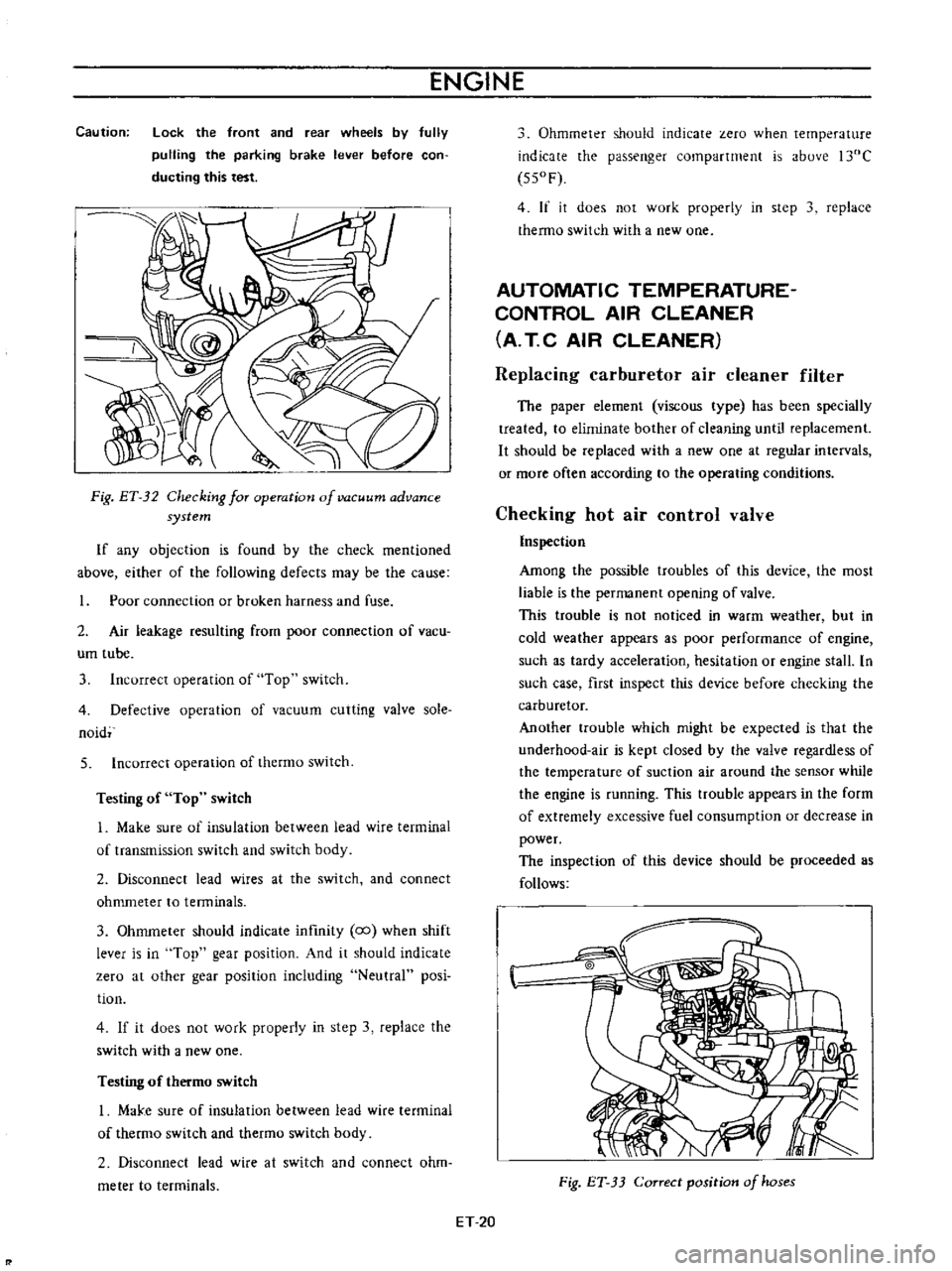
Fig
ET
33
Correct
position
of
hoses
ET
20
Page 335 of 513
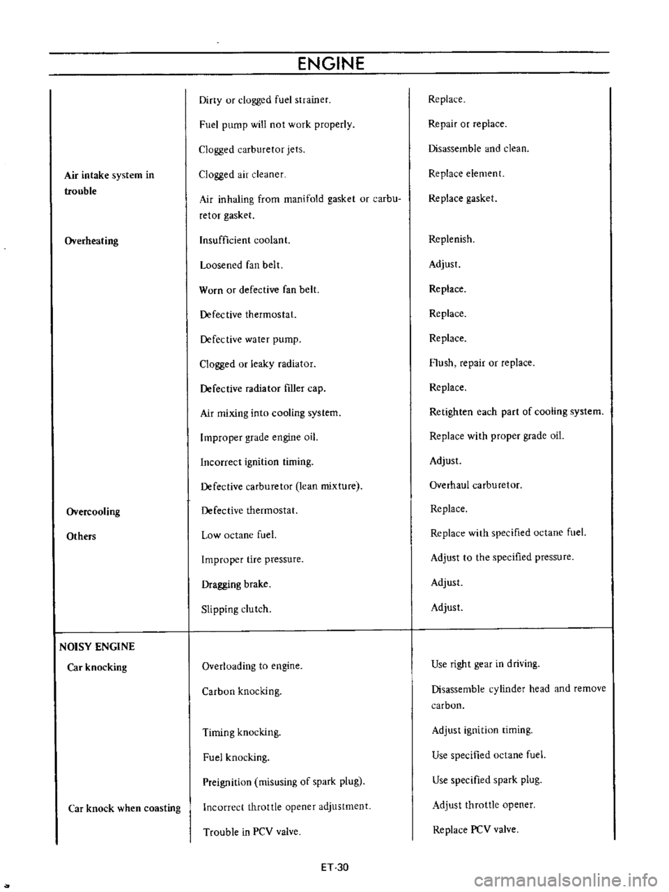
Air
intake
system
in
trouble
Overheating
Overcooling
Others
NOISY
ENGINE
Car
knocking
Car
knock
when
coasting
ENGINE
Diny
ur
clogged
fuel
strainer
Fuel
pump
will
not
work
properly
Clogged
carburetor
jets
Clogged
air
cleaner
Air
inhaling
from
manifold
gasket
or
carbu
retor
gasket
Insufficient
coolant
Loosened
fan
belt
Worn
or
defective
fan
belt
Defective
thermostat
Defective
water
pump
Clogged
or
leaky
radiator
Defective
radiator
filler
cap
Air
mixing
into
cooling
system
Improper
grade
engine
oil
Incorrect
ignition
timing
Defective
carburetor
lean
mixture
Defective
thermostat
Low
octane
fuel
Improper
tire
pressure
Dragging
brake
Slipping
clutch
Overloading
to
engine
Carbon
knocking
Timing
knocking
Fuel
knocking
Preignition
misusing
of
spark
plug
Incorrect
throttle
opener
adjustment
Trouble
in
PCV
valve
ET
30
Replace
Repair
or
replace
Disassemble
and
clean
Replace
element
Replace
gasket
Replenish
Adjust
Replace
Replace
Replace
Flush
repair
or
replace
Replace
Retighten
each
part
of
cooling
system
Replace
with
proper
grade
oil
Adjust
Overhaul
carburetor
Replace
Replace
with
specified
octane
fuel
Adjust
to
the
specified
pressure
Adjust
Adjust
Use
right
gear
in
driving
Disassemble
cylinder
head
and
remove
carbon
Adjust
ignition
timing
Use
specified
octane
fuel
Use
specified
spark
plug
Adjust
throttle
opener
Replace
PCV
valve
Page 405 of 513
ENGINE
AD
JUSTMENT
Idling
adjustment
Idle
mixture
adjustment
requires
the
use
of
a
CO
meter
When
preparing
to
adjust
idle
mixture
it
is
essential
to
have
the
meter
thoroughly
warmed
and
calibrated
Warm
up
the
engine
sufficiently
2
Continue
engine
operation
for
one
minute
under
idling
speed
3
Adjust
throttle
adjusting
screw
so
that
engine
speed
is
800
rpm
in
N
position
for
automatic
transmission
4
Check
ignition
timing
if
necessary
adjust
it
to
the
specifications
Ignition
timing
50
800
rpm
5
Adjust
idle
adjusting
screw
so
that
ca
percentage
is
1
5
t
0
5
6
Repeat
the
adjustments
as
described
in
steps
3
and
5
above
so
that
ca
percentage
is
1
5
to
5
at
800
rpm
Cautions
a
On
automatic
transmission
equipped
model
check
must
be
done
in
the
0
position
Be
sure
to
apply
parking
brake
and
to
lock
both
front
and
rear
wheels
with
wheel
chocks
b
Hold
brake
pedal
while
stepping
down
on
accelerator
pedal
Otherwise
car
will
rush
out
dangerously
7
On
automatic
transmission
equipped
model
make
sure
that
the
adjustment
has
been
made
with
the
selector
lever
in
N
position
And
then
check
the
specifications
with
the
lever
in
D
position
Insure
that
CO
percent
and
idle
speed
are
as
follows
Idle
rpm
650
ca
percentage
with
lever
in
D
position
15
to
5
If
necessary
adjust
by
progressively
turning
throttle
adjusting
screw
and
idle
adjusting
screw
until
correct
adjustments
are
made
Notes
a
Do
not
attempt
to
screw
down
the
id
Ie
adjusting
screw
completely
to
avoid
damage
to
the
EF
14
tip
which
will
tend
to
cause
malfunctions
b
After
idle
adjustment
has
been
made
shift
the
lever
to
N
or
p
position
for
automatic
transmission
c
Remove
wheel
chocks
before
starting
the
car
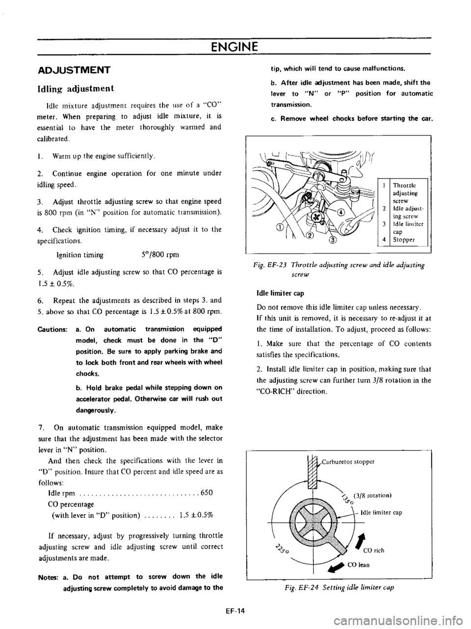
Throttle
adjusting
screw
2
Idle
adjust
ing
crew
3
Idle
limiter
cap
4
Stopp
r
Fig
EF
23
Throttle
adjusting
screw
and
idle
adjusting
screw
Idle
limiter
cap
Do
not
remove
this
idle
limiter
cap
unless
necessary
If
this
unit
is
removed
it
is
necessary
to
fe
adjust
it
at
the
time
of
installation
To
adjust
proceed
as
follows
1
Make
sure
that
the
percentage
of
CO
contents
satisfies
the
specifications
2
Install
idle
limiter
cap
in
position
making
sure
that
the
adjusting
screw
can
further
turn
3
8
rotation
in
the
Ca
RICH
direction
j
j
Carburetor
stopper
o
u
o
i
r
3
8
rotation
0
0
Idle
limiter
cap
0
0
CO
lean
Fig
EF
24
Setting
idle
limite
cap
Page 477 of 513
CLUTCH
CLUTCH
PEDAL
AND
CLUTCH
CONTROL
CABLE
Mechanical
clutch
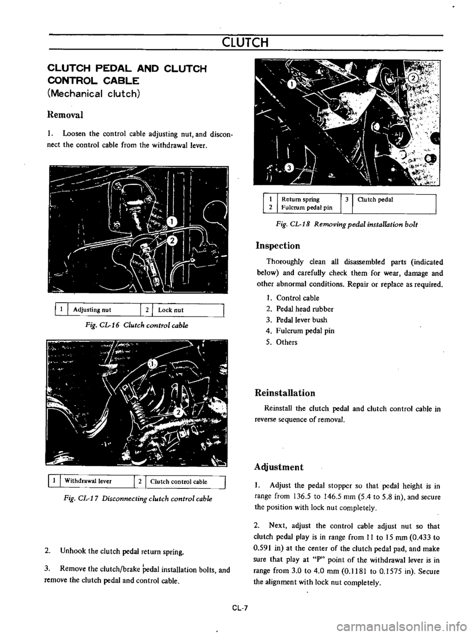
Removal
Loosen
the
control
cable
adjusting
nut
and
discon
nect
the
control
cable
from
the
withdrawal
lever
III
Adjusting
nut
2
I
Lock
nut
Fig
CL
16
Clutch
cunITol
cable
11
I
Withdrawal
lever
I
2
I
Clutch
control
cable
Fig
CL
17
Disconnecting
clutch
control
cable
2
Unhook
the
clutch
pedal
return
spring
3
Remove
the
clutch
brake
Pedal
installation
bolts
and
remove
the
clutch
pedal
and
control
cable
1
I
Return
spring
31
au
tch
pedal
2
Fulcrum
pedal
pin
Fig
CL
I8
Removing
pedal
installation
bolt
Inspection
Thoroughly
clean
all
disassembled
parts
indicated
below
and
carefully
check
them
for
wear
damage
and
other
abnormal
conditions
Repair
or
replace
as
required
Control
cable
2
Pedal
head
rubber
3
Pedal
lever
bush
4
Fulcrum
pedal
pin
5
Others
Reinstallation
Reinstall
the
clutch
pedal
and
clutch
control
cable
in
reverse
sequence
of
removal
Alljustment
Adjust
the
pedal
stopper
so
that
pedal
height
is
in
range
from
136
5
to
146
5
mm
5
4
to
5
8
in
and
secure
the
position
with
lock
nut
completely
2
Next
adjust
the
control
cable
adjust
nut
so
that
clutch
pedal
play
is
in
range
from
II
to
15
mm
0
433
to
0
591
in
at
the
center
of
the
clutch
pedal
pad
and
make
sure
that
play
at
P
point
of
the
withdrawal
lever
is
in
range
from
3
0
to
4
0
mm
0
1181
to
0
1575
in
Secure
the
alignment
with
lock
nut
completely
CL
7
Page 479 of 513
CLUTCH
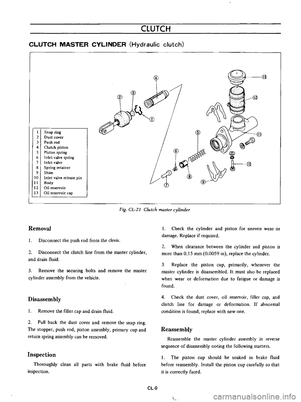
CLUTCH
MASTER
CYLINDER
Hydraulic
clutch
3
V
t
2
3
4
5
6
7
8
9
10
tt
12
13
Snap
ring
Dust
cover
Push
rod
Clutch
piston
Piston
spring
Inlet
valve
spring
Inlet
valve
Spring
retainer
Shim
Inlet
valve
release
pin
Body
Oil
reservoir
Oil
reservoir
cap
6
D
ll
Q
6
i
0
l
Y
r@
cb
Fig
CL
21
Clutch
master
cylinder
Removal
Disconnect
the
push
rod
from
the
clevis
2
Disconnect
the
clutch
line
from
the
master
cylinder
and
drain
fluid
3
Remove
the
securing
bolts
and
remove
the
master
cylinder
assembly
from
the
vehicle
Disassembly
Remove
the
filler
cap
and
drain
fluid
2
Pull
back
the
dust
cover
and
remove
the
snap
ring
The
stopper
push
rod
piston
assembly
primary
cup
and
return
spring
assembly
can
be
removed
Inspection
Thoroughly
clean
all
parts
with
brake
fluid
before
inspection
CL
9
1
Check
the
cylinder
and
piston
for
uneven
wear
or
damage
Replace
if
required
2
When
clearance
between
the
cylinder
and
piston
is
more
than
0
15
mm
0
0059
in
replace
the
cylinder
3
Replace
the
piston
cup
primarily
whenever
the
master
cylinder
is
disassembled
It
must
also
be
replaced
when
wear
or
deforma
tion
due
to
fatigue
or
damage
is
found
4
Check
the
dust
cover
oil
reservoir
filler
cap
and
clutch
line
for
damage
or
deformation
If
abnormal
condition
is
found
replace
with
new
one
Reassembly
Reassemble
the
master
cylinder
assembly
in
reverse
sequence
of
disassembly
noting
the
following
matters
The
piston
cup
should
be
soaked
in
brake
fluid
before
reassembly
Install
the
piston
cup
carefully
so
that
it
is
correctly
faced