Page 480 of 513

CHASSIS
2
Apply
brake
fluid
sufficiently
to
the
cylinder
and
piston
and
assemble
them
Reinstallation
Reinstall
the
master
cylinder
assembly
in
reverse
sequence
of
removal
and
adjust
as
follows
I
Adjust
the
pedal
height
by
changing
the
push
rod
length
2
B
eed
air
out
of
the
hydraulic
system
OPERATING
CYLINDER
Hydraulic
clutch
Removal
Remove
the
return
spring
2
Disconnect
the
clutch
line
from
the
operating
cyl
inder
3
Disconnect
the
push
rod
from
the
withdrawal
lever
4
Release
two
bolts
used
to
mount
the
operating
cylinder
to
the
clutch
housing
Disassembly
1
Remove
the
dust
cover
2
Remove
the
snap
ring
and
all
other
parts
can
be
disassembled
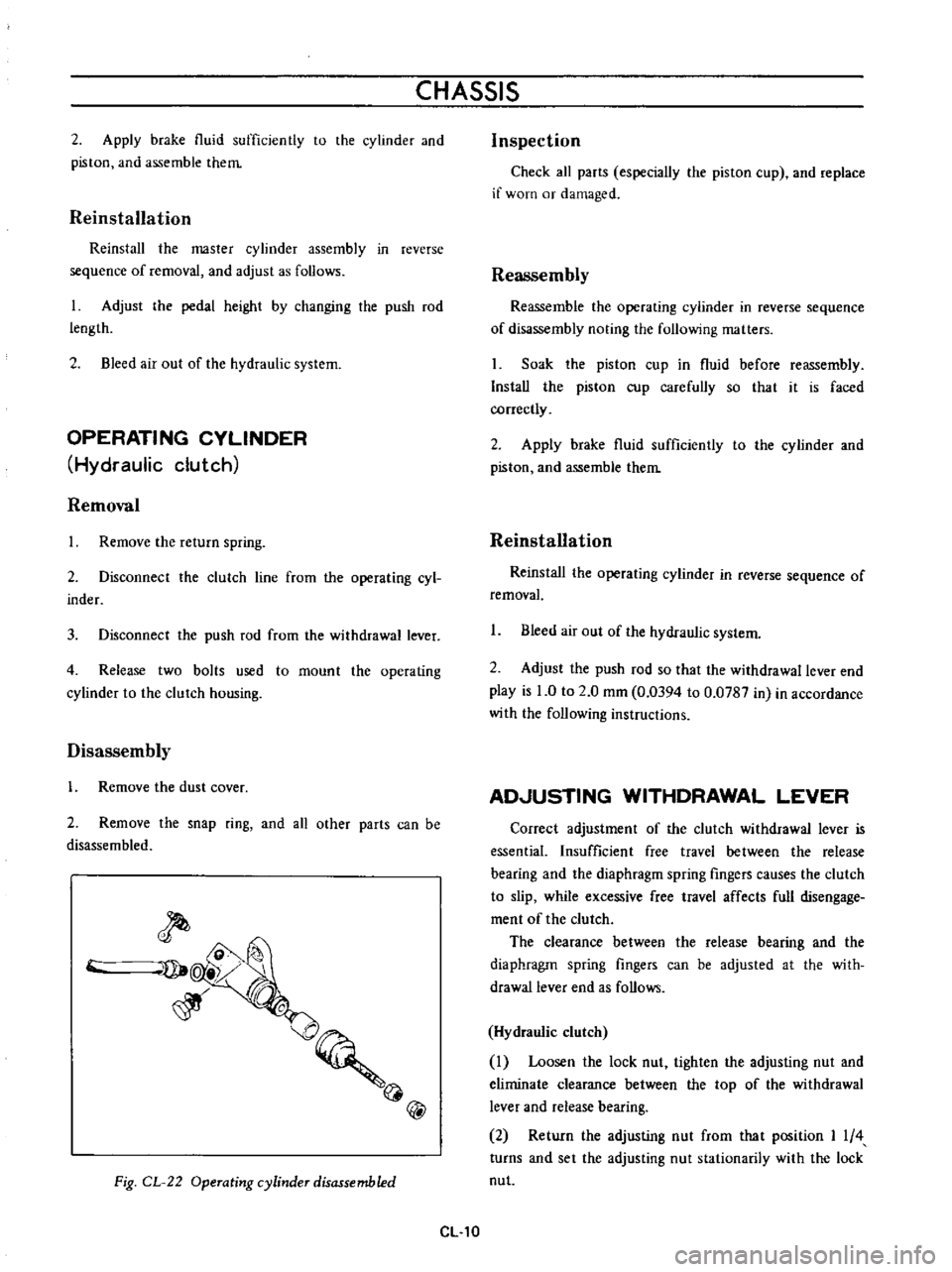
@
Fig
CL
22
Operating
cylinder
disassembled
CL
10
Inspection
Check
all
parts
especially
the
piston
cup
and
replace
if
worn
or
damaged
Reassembly
Reassemble
the
operating
cylinder
in
reverse
sequence
of
disassembly
noting
the
following
matters
Soak
the
piston
cup
in
fluid
before
reassembly
Install
the
piston
cup
carefully
so
that
it
is
faced
correctly
2
Apply
brake
fluid
sufficiently
to
the
cylinder
and
piston
and
assemble
them
Reinstallation
Reinstal
the
operating
cylinder
in
reverse
sequence
of
removal
1
Bleed
air
out
of
the
hydraulic
system
2
Adjust
the
push
rod
so
that
the
withdrawal
lever
end
play
is
0
to
2
0
mm
0
0394
to
0
0787
in
in
accordance
with
the
following
instructions
AD
USTING
WITHDRAWAL
LEVER
Correct
adjustment
of
the
clutch
withdrawal
lever
is
essential
Insufficient
free
travel
between
the
release
bearing
and
the
diaphragm
spring
fingers
causes
the
clutch
to
slip
while
excessive
free
travel
affects
full
disengage
ment
of
the
clutch
The
clearance
between
the
release
bearing
and
the
diaphragm
spring
fingers
can
be
adjusted
at
the
with
drawallever
end
as
follows
Hydraulic
clutch
Loosen
the
lock
nut
tighten
the
adjusting
nut
and
eliminate
clearance
between
the
top
of
the
withdrawal
lever
and
release
bearing
2
Return
the
adjusting
nut
from
that
position
I
4
turns
and
set
the
adjusting
nut
stationarily
with
the
lock
nut
Page 481 of 513

CLUTCH
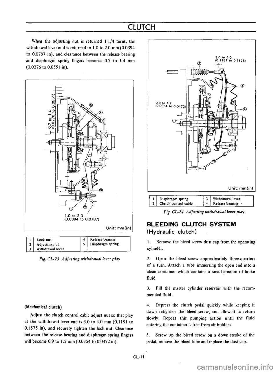
When
the
adjusting
nut
is
returned
I
1
4
turns
the
withdrawal
lever
end
is
returned
to
1
0
to
2
0
mm
0
0394
to
0
0787
in
and
clearance
between
the
release
bearing
and
diaphragm
spring
fingers
becomes
0
7
to
I
4
mm
0
0276
to
0
0551
in
9
@
t
O
to
2
0
0
0394
to
0
0787
Unit
mm
in
I
i
I
I
I
Release
bearing
Diaphragm
spring
Lock
nu
t
Adjusting
nut
Withdrawal
lever
Fig
CL
23
Adjusting
withdrawal
lever
play
Mechanical
clutch
Adjust
the
clutch
control
cable
adjust
nut
so
that
play
at
the
withdrawal
lever
end
is
3
0
to
4
0
mm
0
1181
to
0
1575
in
and
securely
tighten
the
lock
nut
Clearance
between
the
release
bearing
and
diaphragm
spring
fingers
will
become
0
9
to
1
2
mm
0
0354
to
0
0472
in
3
0
to
4
0
0
1181
to
0
1575
@
0
9
to
1
2
I
0
0354
to
0
0472
1
j
E
1
Unit
mm
in
I
I
I
I
Diaphragm
spring
Clutch
control
cable
Withdrawal
lever
Release
bearing
Fig
CL
24
Adjusting
withdrawal
lever
play
BLEEDING
CLUTCH
SYSTEM
Hydraulic
clutch
1
Remove
the
bleed
screw
dust
cap
from
the
operating
cylinder
2
Open
the
bleed
screw
approximately
three
quarters
of
a
turn
Attach
a
tube
immersing
the
open
end
into
a
clean
container
which
contains
a
small
amount
of
brake
fluid
3
Fill
the
master
cylinder
reservoir
with
the
recom
mended
fluid
4
Depress
the
clutch
pedal
quickly
while
keeping
it
down
retighten
the
bleed
screw
and
allow
it
to
return
slowly
Repeat
this
pumping
action
until
the
fluid
entering
the
container
is
free
from
air
bubbles
5
Screw
up
the
bleed
screw
on
a
down
stroke
of
the
pedal
remove
the
bleed
tube
and
replace
the
dust
cap
CL
11
Page 484 of 513

The
clutch
drags
CHASSIS
Weakened
broken
ur
unhooked
clutch
with
drawallever
return
spring
Distorted
or
worn
drive
shaft
Excessive
play
of
release
bearing
on
slip
sleeve
Insufficient
push
rod
length
Excessive
pedal
free
travel
Warped
clutch
disc
Roughened
linings
Improperly
fitted
loose
or
broken
lining
Incorrect
release
bearing
to
diaphragm
spring
fmger
clearance
Clutch
disc
hub
forcing
on
drive
shaft
Damaged
drive
shaft
splines
prevent
the
clutch
disc
from
sliding
Oil
or
grease
on
linings
Warped
or
damaged
pressure
plate
or
clutch
cover
Air
pockets
in
the
hydraulic
system
not
bled
correctly
Dirt
or
foreign
matter
on
sealing
faces
of
master
cylinder
piston
cup
Air
pockets
in
master
cylinder
due
to
loose
piston
Fluid
leakage
from
cylinder
Low
fluid
level
in
reservoir
CL14
Replace
the
spring
or
hook
it
up
as
required
Replace
the
drive
shaft
and
clutch
disc
if
necessary
Replace
the
worn
parts
Adjust
the
push
rod
length
correctly
Adjust
free
travel
correctly
Set
level
of
clutch
disc
if
possible
Maximum
plate
run
out
0
25
mm
0
0098
in
Repolish
linings
with
a
metal
brush
or
replace
them
if
necessary
Replace
linings
Lining
rivets
should
be
clenched
with
no
protrusion
to
avoid
damaging
pressure
plate
and
flywheel
Adjust
correctly
Locate
cause
of
trouble
and
remove
it
if
possible
Otherwise
replace
the
clutch
disc
Replace
the
drive
shaft
also
the
clutch
disc
if
required
Locate
the
cause
of
oil
or
grease
leakage
and
correct
it
as
required
Clean
or
replace
linings
Replace
defective
parts
Bleed
out
completely
Clean
replace
piston
cup
if
damaged
and
bleed
the
system
Replace
piston
cup
and
bleed
the
system
Replace
piston
cup
if
damaged
bleed
the
system
Top
up
with
brake
fluid
and
bleed
the
system
if
necessary