Page 297 of 364

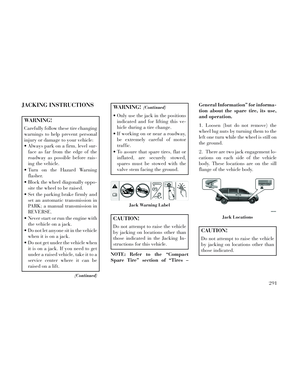
JACKING INSTRUCTIONS
WARNING!
Carefully follow these tire changing
warnings to help prevent personal
injury or damage to your vehicle:
Always park on a firm, level sur-face as far from the edge of the
roadway as possible before rais-
ing the vehicle.
Turn on the Hazard Warning flasher.
Block the wheel diagonally oppo- site the wheel to be raised.
Set the parking brake firmly and set an automatic transmission in
PARK; a manual transmission in
REVERSE.
Never start or run the engine with the vehicle on a jack.
Do not let anyone sit in the vehicle when it is on a jack.
Do not get under the vehicle when it is on a jack. If you need to get
under a raised vehicle, take it to a
service center where it can be
raised on a lift.
(Continued)
WARNING!(Continued)
Only use the jack in the positionsindicated and for lifting this ve-
hicle during a tire change.
If working on or near a roadway, be extremely careful of motor
traffic.
To assure that spare tires, flat or inflated, are securely stowed,
spares must be stowed with the
valve stem facing the ground.
CAUTION!
Do not attempt to raise the vehicle
by jacking on locations other than
those indicated in the Jacking In-
structions for this vehicle.
NOTE: Refer to the “Compact
Spare Tire” section of “Tires – General Information” for informa-
tion about the spare tire, its use,
and operation.
1. Loosen (but do not remove) the
wheel lug nuts by turning them to the
left one turn while the wheel is still on
the ground.
2. There are two jack engagement lo-
cations on each side of the vehicle
body. These locations are on the sill
flange of the vehicle body.CAUTION!
Do not attempt to raise the vehicle
by jacking on locations other than
those indicated.
Jack Warning Label
Jack Locations
291
Page 298 of 364

Rear jack locations are between a pair
of down-facing tabs on the sill flange
of the vehicle side body.
Front jack location is on the sill flange
of the vehicle body and is located 150
mm from door edge.NOTE: In some situations the
jack may need to be placed on its
side in order to be pushed under
the vehicle. Return the jack to its
correct orientation once it is under
the vehicle.
WARNING!
Being under a jacked-up vehicle is
dangerous. The vehicle could slip
off the jack and fall on you. You
could be crushed. Never get any
part of your body under a vehicle
that is on a jack. If you need to get
under a raised vehicle, take it to a
service center where it can be raised
on a lift.
3. Place the wrench on the jack screw
and turn to the right until the jack
head is properly engaged in the de-
scribed location. Do not raise the
vehicle until you are sure the jack
is securely engaged. 4. Raise the vehicle by turning the
jack screw to the right, using the
swivel wrench. Raise the vehicle only
until the tire just clears the surface
and enough clearance is obtained to
install the spare tire. Minimum tire lift
provides maximum stability.WARNING!
Raising the vehicle higher than nec-
essary can make the vehicle less
stable. It could slip off the jack and
hurt someone near it. Raise the ve-
hicle only enough to remove the
tire.
5. Remove the wheel lug nuts, for
vehicles with wheel covers, remove
the cover from the wheel by hand. Do
not pry the wheel cover off. Then pull
the wheel off the hub.
6. Install the compact spare tire.
Lightly tighten the lug nuts.
Rear Jacking Locations
Front Jacking Locations
292
Page 299 of 364

CAUTION!
Be sure to mount the spare tire with
the valve stem facing outward. The
vehicle could be damaged if the
spare tire is mounted incorrectly.
WARNING!
To avoid the risk of forcing the ve-
hicle off the jack, do not tighten the
wheel nuts fully until the vehicle
has been lowered. Failure to follow
this warning may result in personal
injury.
NOTE: Do not install the wheel
cover on the compact spare. 7. Lower the vehicle by turning the
jack screw to the left.
8. Finish tightening the lug nuts.
Push down on the wrench while at the
end of the handle for increased lever-
age. Tighten the lug nuts in a star
pattern until each nut has been tight-
ened twice. Refer to “Torque Specifi-
cations” in this section for proper
wheel lug nut torque. If in doubt
about the correct tightness, have them
checked with a torque wrench by your
authorized dealer or at a service sta-
tion.
9. Lower the jack to its fully-closed
position.WARNING!
A loose tire or jack thrown forward
in a collision or hard stop could
endanger the occupants of the ve-
hicle. Always stow the jack parts
and the spare tire in the places pro-
vided. Have the deflated (flat) tire
repaired or replaced immediately.
10. Place the deflated (flat) tire and
compact spare tire cover assembly in
the rear cargo area.
Do not stow the
deflated tire in the spare tire loca-
tion. Have the full-sized tire repaired
or replaced, as soon as possible.
11. Stow the cable and wheel spacer
before driving the vehicle. Reas-
semble the winch handle extensions to
form a “T” and fit the winch T-handle
over the drive nut. Rotate the nut to
the right until the winch mechanism
clicks at least three times.
NOTE: Refer to the “Spare Tire
Tools” section for instructions on
assembling the T-handle.
12. Stow the jack, jack handle and
winch handle tools back in the stow-
age compartment.
13. Check the compact spare tire
pressure as soon as possible. Correct
the tire pressure, as required.
Mounting Spare Tire
293
Page 300 of 364

SECURING THE SPARE
TIRE
1. Assemble the winch handle exten-
sions to form a T-handle and fit the
winch T-handle over the drive nut.
Rotate the nut to the left until the
winch mechanism stops turning
freely. This will allow enough slack in
the cable to allow you to pull the
wheel spacer out from under the ve-
hicle.
WARNING!
A loose compact spare tire/cover
assembly, thrown forward in a col-
lision or hard stop could endanger
the occupants of the vehicle. Al-
ways stow the compact spare tire
with the cover assembly in the place
provided.
CAUTION!
The winch mechanism is designed
for use with the winch T-handle
only. Use of an air wrench or other
power tools is not recommended
and can damage the winch.
2. Assemble the winch handle exten-
sions to form the spare tire hook, and
pull the wheel spacer from under the
vehicle.
3. Turn the compact spare tire so that
the valve stem is down, and place the
tire into the spare tire/cover assembly.
Slide the wheel spacer through the
center of the wheel and spare tire/
cover assembly, so that the two re-
tainer tabs snap out and engage the
spare tire cover on the opposite side.
CAUTION!
The compact spare tire/cover as-
sembly must be used when the
compact spare tire is stored. Failure
to use this cover could drastically
reduce the life of the compact spare
tire.
WARNING!
Verify that both retainer tabs of the
wheel spacer have been properly
extended through the center of the
wheel and spare tire/cover assem-
bly. Failure to properly engage both
retainer tabs could result in loss of
the spare tire and cover assembly,
which will cause vehicle damage
and may cause loss of vehicle con-
trol.
4. Using the winch T-handle, rotate
the drive nut to the right until the
compact spare tire/cover assembly is
drawn into place against the under-
side of the vehicle.
5. Continue to rotate the nut to the
right until you hear the winch mecha-
nism click three times. It cannot be
overtightened. Check under the ve-
hicle to ensure the compact spare tire/
cover assembly is positioned correctly
against the underside of the vehicle.
294
Page 301 of 364

CAUTION!
The winch mechanism is designed
specifically to stow a compact spare
tire only. Do not attempt to use the
winch to stow the full size flat tire,
or any other full-size tire. Vehicle
damage may result.
ROAD TIRE
INSTALLATION
Vehicles Equipped With Wheel
Covers
1. Mount the road tire on the axle.
2. To ease the installation process for
steel wheels with wheel covers, install
two lug nuts on the mounting studs
which are on each side of the valve
stem. Install the lug nuts with the cone
shaped end of the nut toward the
wheel. Lightly tighten the lug nuts.3. Align the valve notch in the wheel
cover with the valve stem on the
wheel. Install the cover by hand,
snapping the cover over the two lug
nuts. Do not use a hammer or exces-
sive force to install the cover.
4. Install the remaining lug nuts with
the cone shaped end of the nut toward
the wheel. Lightly tighten the lug
nuts.
WARNING!
To avoid the risk of forcing the ve-
hicle off the jack, do not tighten the
wheel nuts fully until the vehicle
has been lowered. Failure to follow
this warning may result in personal
injury.
5. Lower the vehicle to the ground by
turning the jack handle counterclock-
wise.
6. Refer to “Torque Specifications”
in this section for correct lug nut
torque.
7. After 40 km check the lug nut
torque with a torque wrench to ensure
that all lug nuts are properly seated
against the wheel.
Vehicles Without Wheel Covers
1. Mount the road tire on the axle.
2. Install the remaining lug nuts with
the cone shaped end of the nut toward
the wheel. Lightly tighten the lug
nuts.
Tire And Wheel Cover Or Center Cap
1 — Valve Stem 4 — Wheel Cover
2 — Valve Notch 5 — Mounting Stud
3 — Wheel Lug
Nut
295
Page 302 of 364

WARNING!
To avoid the risk of forcing the ve-
hicle off the jack, do not tighten the
wheel nuts fully until the vehicle
has been lowered. Failure to follow
this warning may result in personal
injury.
3. Lower the vehicle to the ground by
turning the jack handle counterclock-
wise.
4. Refer to “Torque Specifications”
in this section for correct lug nut
torque.
5. After 40 km check the lug nut
torque with a torque wrench to ensure
that all lug nuts are properly seated
against the wheel.
JUMP-STARTING
If your vehicle has a discharged bat-
tery it can be jump-started using a set
of jumper cables and a battery in an-
other vehicle or by using a portable
battery booster pack. Jump-starting
can be dangerous if done improperly
so please follow the procedures in this
section carefully. NOTE: When using a portable
battery booster pack follow the
manufacturer’s operating instruc-
tions and precautions.
CAUTION!
Do not use a portable battery
booster pack or any other booster
source with a system voltage
greater than 12 Volts or damage to
the battery, starter motor, alterna-
tor or electrical system may occur.
WARNING!
Do not attempt jump-starting if the
battery is frozen. It could rupture or
explode and cause personal injury.
PREPARATIONS FOR
JUMP-START
The battery in your vehicle is located
on the left side of the engine compart-
ment.
WARNING!
Take care to avoid the radiator
cooling fan whenever the hood is
raised. It can start anytime the
ignition switch is ON. You can be
injured by moving fan blades.
Remove any metal jewelry such as rings, watch bands and brace-
lets that could make an inadver-
tent electrical contact. You could
be seriously injured.
Batteries contain sulfuric acid that can burn your skin or eyes
and generate hydrogen gas which
is flammable and explosive. Keep
open flames or sparks away from
the battery.
Positive Battery Post
296
Page 303 of 364

1. Set the parking brake, shift the
automatic transmission into PARK
and turn the ignition to LOCK.
2. Turn off the heater, radio, and all
unnecessary electrical accessories.
3. If using another vehicle to jump-
start the battery, park the vehicle
within the jumper cables reach, set
the parking brake and make sure the
ignition is OFF.
WARNING!
Do not allow vehicles to touch each
other as this could establish a
ground connection and personal in-
jury could result.
JUMP-STARTING
PROCEDURE
WARNING!
Failure to follow this procedure
could result in personal injury or
property damage due to battery ex-
plosion.
CAUTION!
Failure to follow these procedures
could result in damage to the
charging system of the booster ve-
hicle or the discharged vehicle.
1. Connect the positive (+)end of the
jumper cable to the positive (+)post of
the discharged vehicle.
2. Connect the opposite end of the
positive (+)jumper cable to the posi-
tive (+)post of the booster battery.
3. Connect the negative end (-)of the
jumper cable to the negative (-)post
of the booster battery.
4. Connect the opposite end of the
negative (-)jumper cable to a good
engine ground (exposed metal part of
the discharged vehicle’s engine) away
from the battery and the fuel injection
system.
WARNING!
Do not connect the jumper cable to
the negative (-)post of the dis-
charged battery. The resulting elec-
trical spark could cause the battery
to explode and could result in per-
sonal injury. Only use the specific
ground point, do not use any other
exposed metal parts.
5. Start the engine in the vehicle that
has the booster battery, let the engine
idle a few minutes, and then start the
engine in the vehicle with the dis-
charged battery. Once the engine is
started, remove the jumper cables in
the reverse sequence:
6. Disconnect the negative (-)jumper
cable from the negative (-)post of the
vehicle with the discharged battery.
7. Disconnect the negative end (-)of
the jumper cable from the negative (-)
post of the booster battery.
8. Disconnect the opposite end of the
positive (+)jumper cable from the
positive (+)post of the booster bat-
tery.
297
Page 304 of 364

9. Disconnect the positive(+)end of
the jumper cable from the positive (+)
post of the discharged vehicle.
If frequent jump-starting is required
to start your vehicle you should have
the battery and charging system in-
spected at your authorized dealer.
CAUTION!
Accessories plugged into the vehicle
power outlets draw power from the
vehicle’s battery, even when not in
use (i.e., cellular phones, etc.). Even-
tually, if plugged in long enough
without engine operation, the vehi-
cle’s battery will discharge suffi-
ciently to degrade battery life and/or
prevent the engine from starting.
FREEING A STUCK
VEHICLE
If your vehicle becomes stuck in mud,
sand or snow, it can often be moved
using a rocking motion. Turn the steer-
ing wheel right and left to clear the area
around the front wheels. Then shift
back and forth between DRIVE and REVERSE while gently pressing the
accelerator. Use the least amount of
accelerator pedal pressure that will
maintain the rocking motion, without
spinning the wheels or racing the en-
gine.
CAUTION!
Racing the engine or spinning the
wheels may lead to transmission
overheating and failure. Allow the
engine to idle with the transmission
in NEUTRAL for at least one minute
after every five rocking-motion
cycles. This will minimize overheat-
ing and reduce the risk of transmis-
sion failure during prolonged efforts
to free a stuck vehicle.
NOTE:Press the "ESC Off" switch,
to place the Electronic Stability
Control (ESC) system in "Partial Off"
mode before rocking the vehicle. Re-
fer to “Electronic Brake Control Sys-
tem” in “Starting and Operating” for
further information. Once the ve-
hicle has been freed, press the "ESC
Off" switch again to restore "ESC
On" mode.
CAUTION!
When “rocking” a stuck vehicle by shifting between DRIVE and
REVERSE, do not spin the
wheels faster than 24 km/h, or
drivetrain damage may result.
Revving the engine or spinning the wheels too fast may lead to
transmission overheating and
failure. It can also damage the
tires. Do not spin the wheels
above 48 km/h while in gear (no
transmission shifting occurring).
WARNING!
Fast spinning tires can be danger-
ous. Forces generated by excessive
wheel speeds may cause damage, or
even failure, of the axle and tires. A
tire could explode and injure some-
one. Do not spin your vehicle's
wheels faster than 48 km/h or for
longer than 30 seconds continu-
ously without stopping when you
are stuck and do not let anyone
near a spinning wheel, no matter
what the speed.
298