Page 289 of 364

Use speed control in flat terrain andwith light loads to maximize fuel
efficiency.
Cooling System
To reduce potential for engine and
transmission overheating, take the
following actions:
City Driving
When stopped for short periods, shift
the transmission into NEUTRAL and
increase engine idle speed.
Highway Driving
Reduce speed.
Air Conditioning
Turn off temporarily. Trailer Hitch Attaching Points
Your vehicle will require extra equip-
ment to tow a trailer safely and effi-
ciently. The trailer tow hitch must be
attached to your vehicle using the
provided attaching points on the ve-
hicle's frame. Refer to the following
chart to determine the accurate at-
taching points. Other equipment,
such as trailer sway controls and
braking equipment, trailer equalizing
(leveling) equipment and low profile
mirrors, may also be required or
strongly recommended.
Trailer Tow Hitch Attaching
Points And Overhang Dimen- sions
Grand Voyager
A N/A
B 441.72 mm
C 568.61 mm
D 763.62 mm
E (maximum
overhang) 1185.40 mm
F 670.20 mm
283
Page 290 of 364

RECREATIONAL TOWING (BEHIND MOTORHOME, ETC.)
TOWING THIS VEHICLE
BEHIND ANOTHER VEHICLE
Towing ConditionWheels OFF the Ground All Models
Flat Tow NONENOT ALLOWED
Dolly Tow Front
OK
Rear NOT ALLOWED
On Trailer ALLOK
RECREATIONAL TOWING –
ALL MODELS
Recreational towing is allowed ONLY
if the front wheels are OFF the
ground. This may be accomplished
using a tow dolly or vehicle trailer. If
using a tow dolly, follow this proce-
dure:
1. Properly secure the dolly to the
tow vehicle, following the dolly
manufacturer's instructions.
2. Drive the front wheels onto the
tow dolly. 3. Firmly apply the parking brake.
Place the transmission in PARK.
4. Properly secure the front wheels to
the dolly, following the dolly manu-
facturer's instructions.
5. Release the parking brake.
CAUTION!
DO NOT flat tow this vehicle. Dam-
age to the drivetrain will result.
CAUTION!
Towing this vehicle in violation of
the above requirements can cause
severe transmission damage. Dam-
age from improper towing is not
covered under the New Vehicle
Limited Warranty.
284
Page 291 of 364
6
WHAT TO DO IN EMERGENCIES
HAZARD WARNING FLASHERS.............286
IF YOUR ENGINE OVERHEATS ..............286
WHEEL AND TIRE TORQUE SPECIFICATIONS . . .287
TORQUE SPECIFICATIONS ...............287
JACKING AND TIRE CHANGING .............287
JACK LOCATION ...................... .288
SPARE TIRE REMOVAL .................288
TO ACCESS SPARE TIRE WINCH DRIVE NUT. . .288
SPARE TIRE TOOLS .................... .289
SPARE TIRE REMOVAL INSTRUCTIONS .....289
PREPARATIONS FOR JACKING ............290
JACKING INSTRUCTIONS ................291
SECURING THE SPARE TIRE .............294
ROAD TIRE INSTALLATION ..............295
JUMP-STARTING ....................... .296
PREPARATIONS FOR JUMP-START .........296
JUMP-STARTING PROCEDURE ............297
FREEING A STUCK VEHICLE ...............298
TOWING A DISABLED VEHICLE ............299
SHIFT LEVER OVERRIDE .................300
285
Page 292 of 364

HAZARD WARNING
FLASHERS
The Hazard Warning flasher switch is
located in the lower center area of the
instrument panel.Press the switch to turn on the
Hazard Warning flasher.
When the switch is activated, all di-
rectional turn signals will flash on and
off to warn oncoming traffic of an
emergency. Press the switch a second
time to turn off the Hazard Warning
flashers.
This is an emergency warning system
and it should not be used when the
vehicle is in motion. Use it when your
vehicle is disabled and it is creating a
safety hazard for other motorists.
When you must leave the vehicle to
seek assistance, the Hazard Warning
flashers will continue to operate even
though the ignition is placed in the
OFF position.
NOTE: With extended use the
Hazard Warning flashers may
wear down your battery.
IF YOUR ENGINE
OVERHEATS
In any of the following situations, you
can reduce the potential for overheat-
ing by taking the appropriate action.
On the highways — slow down.
In city traffic — while stopped, place the transmission in NEU-
TRAL, but do not increase engine
idle speed.
NOTE: There are steps that you
can take to slow down an impend-
ing overheat condition:
If your air conditioner (A/C) is on, turn it off. The A/C system
adds heat to the engine cooling
system and turning the A/C off
can help remove this heat.
You can also turn the tempera- ture control to maximum heat,
the mode control to floor and the
blower control to high. This al-
lows the heater core to act as a
supplement to the radiator and
aids in removing heat from the
engine cooling system.
CAUTION!
Driving with a hot cooling system
could damage your vehicle. If tem-
perature gauge reads “H”, pull over
and stop the vehicle. Idle the ve-
hicle with the air conditioner
turned off until the pointer drops
back into the normal range. If the
pointer remains on the “H”, turn
the engine off immediately, and call
for service.
WARNING!
You or others can be badly burned
by hot engine coolant (antifreeze)
or steam from your radiator. If you
see or hear steam coming from un-
der the hood, do not open the hood
until the radiator has had time to
cool. Never try to open a cooling
system pressure cap when the ra-
diator or coolant bottle is hot.
286
Page 293 of 364

WHEEL AND TIRE
TORQUE
SPECIFICATIONS
Proper lug nut/bolt torque is very im-
portant to ensure that the wheel is
properly mounted to the vehicle. Any
time a wheel has been removed and
reinstalled on the vehicle the lug nuts/
bolts should be torqued using a prop-
erly calibrated torque wrench.
TORQUE SPECIFICATIONS
Lug Nut/Bolt
Torque **Lug
Nut/Bolt
Size Lug
Nut/Bolt Socket Size
135 N·m M12 x
1.25 19 mm
**Use only LANCIA recommended
lug nuts/bolts and clean or remove
any dirt or oil before tightening.
Inspect the wheel mounting surface
prior to mounting the tire and remove
any corrosion or loose particles. Tighten the lug nuts/bolts in a star
pattern until each nut/bolt has been
tightened twice.
After 40 km check the lug nut/bolt
torque to be sure that all the lug nuts/
bolts are properly seated against the
wheel.
WARNING!
To avoid the risk of forcing the ve-
hicle off the jack, do not tighten the
lug nuts fully until the vehicle has
been lowered. Failure to follow this
warning may result in personal in-
jury.
JACKING AND TIRE
CHANGING
WARNING!
Do not attempt to change a tire on
the side of the vehicle close to
moving traffic. Pull far enough
off the road to avoid the danger of
being hit when operating the jack
or changing the wheel.
(Continued)
Wheel Mounting Surface
Torque Patterns
287
Page 294 of 364

WARNING!(Continued)
Being under a jacked-up vehicleis dangerous. The vehicle could
slip off the jack and fall on you.
You could be crushed. Never put
any part of your body under a
vehicle that is on a jack. If you
need to get under a raised vehicle,
take it to a service center where it
can be raised on a lift.
Never start or run the engine while the vehicle is on a jack.
The jack is designed to be used as a tool for changing tires only. The
jack should not be used to lift the
vehicle for service purposes. The
vehicle should be jacked on a firm
level surface only. Avoid ice or
slippery areas.
JACK LOCATION
The jack, jack handle and winch
handle tools are stowed behind the
rear left side trim panel in the rear
cargo area. Turn the two cover latches
to release the cover. Remove the pouch containing the
scissors jack, jack handle, and tools.
SPARE TIRE REMOVAL
The spare tire is stowed inside a protec-
tive cover located under the center of
the vehicle between the front doors by
means of a cable winch mechanism.
The “spare tire drive” nut is located on
the floor, under a plastic cap at the
front of the floor console or under front
super console forward bin liner.
TO ACCESS SPARE TIRE
WINCH DRIVE NUT
To access the spare tire winch drive
nut and lower the spare tire, you will
need to refer to one of the following
center console configurations.
Super Console
For vehicles equipped with the Super
Console, the spare tire winch assem-
bly drive nut is located beneath the
console.
1. Pull the lower drawer out from the
rear of the floor console to gain clear
access of the tire winch drive nut.
Jack And Tool Location
Spare Tire Location
Super Console
1 — Lower Drawer
2 — Front Drawer
3 — Front Drawer Liner
288
Page 295 of 364

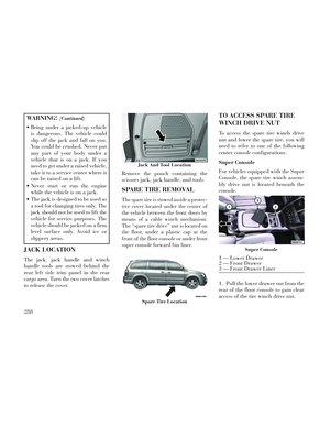
2. Open the front drawer to expose
the storage compartment.
3. Remove the liner from the con-
sole's storage compartment to access
the spare tire winch drive nut.
Premium/Base/Cargo Center
Console
Pull the Winch Cover assembly plug
(for versions/markets, where pro-
vided) to access the winch drive nut.SPARE TIRE TOOLS
The tool pouch contains three pieces
and can be assembled into a spare tire
hook; to remove the compact spare
tire/cover assembly from under the
vehicle, or a Winch T-handle; to raise/
lower the compact spare tire/cover as-
sembly.
SPARE TIRE REMOVAL
INSTRUCTIONS
The spare tire is located under the ve-
hicle beneath the center console area.
1. Assemble the spare tire tools into a
T-handle and place the square end
over the spare tire winch drive nut.
Drive Nut Access
Winch Cover Assembly Plug (for
versions/markets, where provided)
Assembled T-handle
A — Spare Tire Hook/T-handle
B — Extension 1
C — Extension 2
Assembling The Spare Tire Hook
A — Spare Tire Hook/T-handle
B — Extension 1
C — Extension 2
Spare Tire And Cover
289
Page 296 of 364

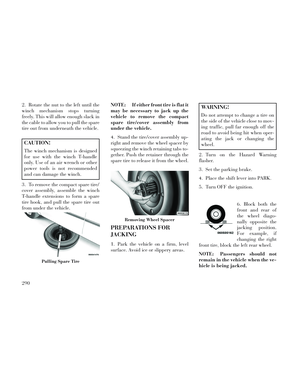
2. Rotate the nut to the left until the
winch mechanism stops turning
freely. This will allow enough slack in
the cable to allow you to pull the spare
tire out from underneath the vehicle.
CAUTION!
The winch mechanism is designed
for use with the winch T-handle
only. Use of an air wrench or other
power tools is not recommended
and can damage the winch.
3. To remove the compact spare tire/
cover assembly, assemble the winch
T-handle extensions to form a spare
tire hook, and pull the spare tire out
from under the vehicle. NOTE: If either front tire is flat it
may be necessary to jack up the
vehicle to remove the compact
spare tire/cover assembly from
under the vehicle.
4. Stand the tire/cover assembly up-
right and remove the wheel spacer by
squeezing the winch retaining tabs to-
gether. Push the retainer through the
spare tire to release it from the wheel.
PREPARATIONS FOR
JACKING
1. Park the vehicle on a firm, level
surface. Avoid ice or slippery areas.
WARNING!
Do not attempt to change a tire on
the side of the vehicle close to mov-
ing traffic, pull far enough off the
road to avoid being hit when oper-
ating the jack or changing the
wheel.
2. Turn on the Hazard Warning
flasher.
3. Set the parking brake.
4. Place the shift lever into PARK.
5. Turn OFF the ignition.
6. Block both the
front and rear of
the wheel diago-
nally opposite the
jacking position.
For example, if
changing the right
front tire, block the left rear wheel.
NOTE: Passengers should not
remain in the vehicle when the ve-
hicle is being jacked.
Pulling Spare Tire
Removing Wheel Spacer
290