Page 257 of 364

ESC Activation/Malfunction
Indicator Light And ESC OFF
Indicator Light
The “ESC Activation/
Malfunction Indicator
Light” in the instrument
cluster will come on when
the ignition switch is turned to the ON
position. It should turn off with the
engine running. If the “ESC
Activation/Malfunction Indicator
Light” comes on continuously with the
engine running, a malfunction has
been detected in the ESC system. If this
light remains on after several ignition
cycles, and the vehicle has been driven
several kilometers at speeds greater
than 48 km/h, see your authorized
dealer as soon as possible to have the
problem diagnosed and corrected.
The “ESC Activation/Malfunction In-
dicator Light” (located in the instru-
ment cluster) starts to flash as soon as
the tires lose traction and the ESC sys-
tem becomes active. The “ESC
Activation/Malfunction Indicator
Light” also flashes when TCS is active. If the “ESC Activation/Malfunction In-
dicator Light” begins to flash during
acceleration, ease up on the accelerator
and apply as little throttle as possible.
Be sure to adapt your speed and driving
to the prevailing road conditions.
NOTE:
The “ESC Activation/Malfunction
Indicator Light” and the “ESC
OFF Indicator Light” come on
momentarily each time the igni-
tion switch is turned ON.
Each time the ignition is turned
ON, the ESC system will be ON
even if it was turned off
previously.
The ESC system will make buzz- ing or clicking sounds when it is
active. This is normal; the
sounds will stop when ESC be-
comes inactive following the
maneuver that caused the ESC
activation.
The “ESC OFF Indicator
Light” indicates the Elec-
tronic Stability Control
(ESC) is off.
TRAILER SWAY CONTROL
(TSC)
TSC uses sensors in the vehicle to
recognize an excessively swaying
trailer and will take the appropriate
actions to attempt to stop the sway.
The system may reduce engine power
and apply the brake of the appropri-
ate wheel(s) to counteract the sway of
the trailer. TSC will become active
automatically once an excessively
swaying trailer is recognized. No
driver action is required. Note that
TSC cannot stop all trailers from
swaying. Always use caution when
towing a trailer and follow the trailer
tongue weight recommendations. Re-
fer to “Trailer Towing” in this section
for further information. When TSC is
functioning, the “ESC Activation/
Malfunction Indicator Light” will
flash, the engine power may be re-
duced and you may feel the brakes
being applied to individual wheels to
attempt to stop the trailer from sway-
ing. TSC is disabled when the ESC
system is in the “Partial Off” mode.
251
Page 258 of 364

WARNING!
If TSC activates while driving, slow
the vehicle down, stop at the near-
est safe location, and adjust the
trailer load to eliminate trailer
sway.
HILL START ASSIST (HSA)
The HSA system is designed to assist
the driver when starting a vehicle
from a stop on a hill. HSA will main-
tain the level of brake pressure the
driver applied for a short period of
time after the driver takes their foot
off of the brake pedal. If the driver
does not apply the throttle during this
short period of time, the system will
release brake pressure and the vehicle
will roll down the hill. The system will
release brake pressure in proportion
to the amount of throttle applied as
the vehicle starts to move in the in-
tended direction of travel.
TIRE SAFETY
INFORMATION
Tire Markings
NOTE:
P (Passenger) - Metric tire sizing
is based on U.S. design standards.
P-Metric tires have the letter “P”
molded into the sidewall preced-
ing the size designation. Ex-
ample: P215/65R15 95H.
European-Metric tire sizing isbased on European design stan-
dards. Tires designed to this
standard have the tire size
molded into the sidewall begin-
ning with the section width. The
letter "P" is absent from this tire
size designation.
Example: 215/65R15 96H.
LT (Light Truck) - Metric tire siz-
ing is based on U.S. design stan-
dards. The size designation for
LT-Metric tires is the same as for
P-Metric tires except for the let-
ters “LT” that are molded into the
sidewall preceding the size desig-
nation. Example: LT235/85R16.
1—U.S.DOT
Safety Standards
Code (TIN) 4 — Maximum
Load
2—
Size Designa-
tion5 — Maximum
Pressure
3 — Service De-
scription 6 — Treadwear,
Traction and Tem-
perature Grades
252
Page 259 of 364
Temporary spare tires are de-signed for temporary emergency
use only. Temporary high pres-
sure compact spare tires have
the letter “T” or “S” molded into
the sidewall preceding the size
designation.
Example: T145/80D18 103M. High flotation tire sizing is
based on U.S. design standards
and it begins with the tire diam-
eter molded into the sidewall.
Example: 31x10.5 R15 LT.
Tire Sizing Chart
EXAMPLE:
Size Designation: P= Passenger car tire size based on U.S. design standards
"....blank...." = Passenger car tire based on European design standards
LT = Light truck tire based on U.S. design standards
TorS= Temporary spare tire
31 = Overall diameter in inches (in)
215 = Section width in millimeters (mm)
65 = Aspect ratio in percent (%)
— Ratio of section height to section width of tire
10.5 = Section width in inches (in)
R = Construction code
— "R" means radial construction
— "D" means diagonal or bias construction
15 = Rim diameter in inches (in)
253
Page 260 of 364
EXAMPLE:
Service Description: 95= Load Index
— A numerical code associated with the maximum load a tire can carry
H = Speed Symbol
— A symbol indicating the range of speeds at which a tire can carry a load corresponding to its
load index under certain operating conditions
— The maximum speed corresponding to the speed symbol should only be achieved under speci-
fied operating conditions (i.e., tire pressure, vehicle loading, road conditions, and posted speed
limits)
Load Identification: "....blank...." = Absence of any text on the sidewall of the tire indicates a Standard Load (SL) tire
Extra Load (XL) = Extra load (or reinforced) tire
Light Load (LL) = Light load tire
C, D, E, F, G = Load range associated with the maximum load a tire can carry at a specified pressure
Maximum Load— Maximum load indicates the maximum load this tire is designed to carry
Maximum Pressure— Maximum pressure indicates the maximum permissible cold tire inflation pressure for this tire
254
Page 261 of 364

Tire Identification Number
(TIN)
The TIN may be found on one or both
sides of the tire, however, the datecode may only be on one side. Tires
with white sidewalls will have the full
TIN, including the date code, located
on the white sidewall side of the tire.
Look for the TIN on the outboard sideof black sidewall tires as mounted on
the vehicle. If the TIN is not found on
the outboard side, then you will find it
on the inboard side of the tire.
EXAMPLE:
DOT MA L9 ABCD 0301
DOT = Department of Transportation
— This symbol certifies that the tire is in compliance with the U.S. Department of Transportation tire safety
standards and is approved for highway use
MA = Code representing the tire manufacturing location (two digits)
L9 = Code representing the tire size (two digits)
ABCD = Code used by the tire manufacturer (one to four digits)
03 = Number representing the week in which the tire was manufactured (two digits)
— 03 means the 3rd week
01 = Number representing the year in which the tire was manufactured (two digits)
— 01 means the year 2001
— Prior to July 2000, tire manufacturers were only required to have one number to represent the year in
which the tire was manufactured. Example: 031 could represent the 3rd week of 1981 or 1991
255
Page 262 of 364

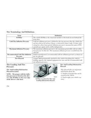
Tire Terminology And Definitions
TermDefinition
B-Pillar The vehicle B-Pillar is the structural member of the body located behind the
front door.
Cold Tire Inflation Pressure Cold tire inflation pressure is defined as the tire pressure after the vehicle has
not been driven for at least 3 hours, or driven less than 1 mile (1.6 km) after
sitting for a three hour period. Inflation pressure is measured in units of PSI
(pounds per square inch) or kPa (kilopascals).
Maximum Inflation Pressure The maximum inflation pressure is the maximum permissible cold tire infla-
tion pressure for this tire. The maximum inflation pressure is molded into the
sidewall.
Recommended Cold Tire Inflation Pressure Vehicle manufacturer's recommended cold tire inflation pressure as shown on
the tire placard.
Tire Placard A paper label permanently attached to the vehicle describing the vehicle’s
loading capacity, the original equipment tire sizes and the recommended cold
tire inflation pressures.
Tire Loading And Tire
Pressure
Tire And Loading Information
Placard Location
NOTE: The proper cold tire infla-
tion pressure is listed on the driv-
er’s side B-Pillar or the rear edge
of the driver's side door. Tire And Loading Information
Placard
This placard tells you important
information about the:
1) Number of people that can be
carried in the vehicle.
2) Total weight your vehicle can
carry.
B-Pillar Location For Tire And Loading Information Placard
256
Page 263 of 364

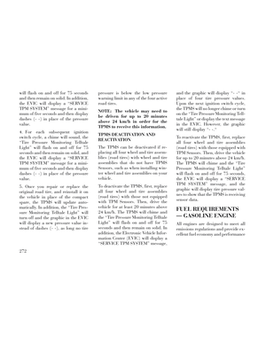
3)Tire size designed for your vehicle.
4) Cold tire inflation pressures for
the front, rear, and spare tires.
Loading
The vehicle maximum load on the tire
must not exceed the load carrying ca-
pacity of the tire on your vehicle. You
will not exceed the tire's load carrying
capacity if you adhere to the loading
conditions, tire size, and cold tire in-
flation pressures specified on the Tire
and Loading Information placard and
in the “Vehicle Loading” section of
this manual.
NOTE: Under a maximum loaded
vehicle condition, gross axle
weight ratings (GAWRs) for the
front and rear axles must not be
exceeded. For further information
on GAWRs, vehicle loading, and
trailer towing, refer to “Vehicle
Loading” in this section.
To determine the maximum loading
conditions of your vehicle, locate the
statement “The combined weight of
occupants and cargo should never ex-
ceed XXX lbs or XXX kg” on the Tire and Loading Information placard.
The combined weight of occupants,
cargo/luggage and trailer tongue
weight (if applicable) should never
exceed the weight referenced here.
Steps For Determining Correct
Load Limit
1. Locate the statement “The com-
bined weight of occupants and cargo
should never exceed XXX lbs or
XXX kg” on your vehicle's placard.
2. Determine the combined weight of
the driver and passengers that will be
riding in your vehicle.
3. Subtract the combined weight of
the driver and passengers from
XXX lbs or XXX kg.
4.
The resulting figure equals the
available amount of cargo and luggage
load capacity. For example, if “XXX”
amount equals 1,400 lbs (635 kg) and
there will be five 150 lb (68 kg) passen-
gers in your vehicle, the amount of
available cargo and luggage load capac-
ity is 650 lbs (295 kg) (since 5 x 150 lbs (68 kg) = 750 lbs (340 kg), and
1400 lbs (635 kg) – 750 lbs (340 kg) =
650 lbs [295 kg]).
5.Determine the combined weight of
luggage and cargo being loaded on the
vehicle. That weight may not safely
exceed the available cargo and luggage
load capacity calculated in Step 4.
NOTE:
If your vehicle will be towing a trailer, load from your trailer
will be transferred to your ve-
hicle. The following table shows
examples on how to calculate to-
tal load, cargo/luggage, and
towing capacities of your vehicle
with varying seating configura-
tions and number and size of
occupants. This table is for il-
lustration purposes only and
may not be accurate for the seat-
ing and load carry capacity of
your vehicle.
For the following example, the combined weight of occupants
and cargo should never exceed
865 lbs (392 kg).
257
Page 264 of 364
WARNING!
Overloading of your tires is danger-
ous. Overloading can cause tire
failure, affect vehicle handling, and
increase your stopping distance.
Use tires of the recommended load
capacity for your vehicle. Never
overload them.
TIRES — GENERAL
INFORMATION
Tire Pressure
Proper tire inflation pressure is essen-
tial to the safe and satisfactory opera-
tion of your vehicle. Three primary
areas are affected by improper tire
pressure:Safety
WARNING!
Improperly inflated tires are dan-
gerous and can cause collisions.
Under-inflation increases tire flexing and can result in over-
heating and tire failure.
(Continued)
258