Page 265 of 279

17B-265
AFTER REPAIRCarry out a road test, then check with the diagnostic tool.
V2 MR-376-X76-17B050$180.mif
PETROL INJECTION
Fault finding – Tests17B
V42 Injection
Program No.: 2A
Vdiag No.: 04, 05, 06,
14, 16, 18
TEST 10
CONTINUED
Check the resistance of the TDC sensor between connections 3BL and 3BG on the injection computer
connector side, component code 120 (see MR 388 (Logan and Sandero), MR 451 (Duster), MR 423 (Thalia 2/
Symbol 2), MR 430 (Clio II F 6) or MR 374 (Kangoo VLL), Mechanical, 17B, Petrol injection, Petrol injection
computer: Removal - Refitting).
The resistance must be between 175 X 295 or 200 < X < 270 (F4R engine of Duster) (between 0°C
and 40°C). If the value is not correct, replace the sensor (see MR 388 (Logan and Sandero), MR 451 (Duster),
MR 423 (Thalia 2/Symbol 2), MR 430 (Clio II F 6) or MR 374 (Kangoo VLL), Mechanical, 17B, Petrol Injection,
Crankshaft position sensor: Removal - Refitting).
Check the insulation, continuity and the absence of interference resistance on the following connections:
–3BL between components 120 and 149,
–3BG between components 120 and 149.
If the connection or connections are faulty and there is a repair procedure (see Technical Note 6015A, Electrical
wiring repair, Wiring: Precautions for repair), repair the wiring, otherwise replace it.
If the fault is still present, contact the Techline.
Page 266 of 279

17B-266
AFTER REPAIRCarry out a road test, then check with the diagnostic tool.
V2 MR-376-X76-17B050$180.mif
PETROL INJECTION
Fault finding – Tests17B
V42 Injection
Program No.: 2A
Vdiag No.: 04, 05, 06,
14, 16, 18
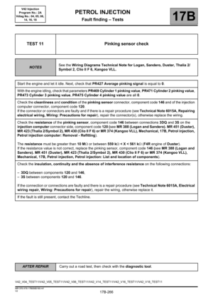
TEST 11 Pinking sensor check
NOTESSee the Wiring Diagrams Technical Note for Logan, Sandero, Duster, Thalia 2/
Symbol 2, Clio II F 6, Kangoo VLL.
Start the engine and let it idle. Next, check that PR427 Average pinking signal is equal to 0.
With the engine idling, check that parameters PR469 Cylinder 1 pinking value, PR471 Cylinder 2 pinking value,
PR473 Cylinder 3 pinking value, PR475 Cylinder 4 pinking value are all 0.
Check the cleanliness and condition of the pinking sensor connector, component code 146 and of the injection
computer connector, component code 120.
If the connector or connectors are faulty and if there is a repair procedure (see Technical Note 6015A, Repairing
electrical wiring, Wiring: Precautions for repair), repair the connector(s), otherwise replace the wiring.
Check the resistance of the pinking sensor, component code 146 between connections 3DQ and 3S on the
injection computer connector side, component code 120 (see MR 388 (Logan and Sandero). MR 451 (Duster),
MR 423 (Thalia 2/Symbol 2), MR 430 (Clio II F 6) or MR 374 (Kangoo VLL), Mechanical, 17B, Petrol injection,
Petrol injection computer: Removal - Refitting).
The resistance must be greater than 10 M or between 559 k < X < 561 k (F4R engine of Duster).
If the resistance value is not correct, replace the pinking sensor, component code 146 (see MR 388 (Logan and
Sandero). MR 451 (Duster), MR 423 (Thalia 2/Symbol 2), MR 430 (Clio II F 6) or MR 374 (Kangoo VLL),
Mechanical, 17B, Petrol injection, Petrol injection: List and location of components).
Check the insulation, continuity and the absence of interference resistance on the following connections:
–3DQ between components 120 and 146,
–3S between components 120 and 146.
If the connection or connections are faulty and there is a repair procedure (see Technical Note 6015A, Electrical
wiring repair, Wiring: Precautions for repair), repair the wiring, otherwise replace it.
If the fault is still present, contact the Techline.
V42_V04_TEST11/V42_V05_TEST11/V42_V06_TEST11/V42_V14_TEST11/V42_V16_TEST11/V42_V18_TEST11
Page 267 of 279

17B-267
AFTER REPAIRCarry out a road test, then check with the diagnostic tool.
V2 MR-376-X76-17B050$180.mif
PETROL INJECTION
Fault finding – Tests17B
V42 Injection
Program No.: 2A
Vdiag No.: 04, 05, 06,
14, 16, 18
TEST 12 Additional fuel tank pump check
NOTESSee the Wiring Diagrams Technical Note for Logan, Sandero.
Listen to the operation of the additional fuel pump and of the petrol pump relay of the additional circuit by running
command AC224 Additional petrol circuit pump relay.
Check the supply of the solenoid valve using a test light, by running command AC224.
If the supply is correct, replace the additional fuel pump (see MR 388 or MR 374 Mechanical, 19C, Tank,
Additional fuel tank: Removal – Refitting).
Check the continuity, insulation, and absence of interference resistance on the following connections:
–3ACL between components 1639 and 283,
–NH (for Logan, Sandero, Duster) or M (for Thalia 2/Symbol 2) or MHA (for Clio II F 6) or MH (for Kangoo VLL)
between the earth and 283.
If the connection or connections are faulty and there is a repair procedure (see Technical Note 6015A, Electrical
wiring repair, Wiring: Precautions for repair), repair the wiring, otherwise replace it.
If the checks are correct, run fault finding on the Protection and Switching Unit.
If the fault is still present, contact the techline.
V42_V04_TEST12/V42_V05_TEST12/V42_V06_TEST12/V42_V14_TEST12/V42_V16_TEST12/V42_V18_TEST12
Page 268 of 279

17B-268
AFTER REPAIRCarry out a road test, then check with the diagnostic tool.
V2 MR-376-X76-17B050$180.mif
PETROL INJECTION
Fault finding – Tests17B
V42 Injection
Program No.: 2A
Vdiag No.: 04, 05, 06,
14, 16, 18
TEST 13 Injector check
NOTESSee the Wiring Diagrams Technical Note for Logan, Sandero, Duster, Thalia 2/
Symbol 2, Clio II F 6, Kangoo VLL.
Perform a visual inspection of the condition and possible leaks in the system.
Repair if necessary (see MR 388 (Logan and Sandero), Mechanical, 13A, Fuel supply, Injector rail - Injectors:
Removal - Refitting, MR 451 (Duster), MR 423 (Thalia 2/Symbol 2), MR 430 (Clio II F 6) or MR 374 (Kangoo
VLL), Mechanical, 17B, Petrol injection, Injector rail - Injectors: Removal - Refitting).
Listen to the operation of the injectors by running the commands:
–AC005 Cylinder 1 injector,
–AC006 Cylinder 2 injector,
–AC007 Cylinder 3 injector,
–AC008 Cylinder 4 injector.
Replace the injectors if necessary (see MR 388 (Logan and Sandero), Mechanical, 13A, Fuel supply, Injector
rail - Injectors: Removal - Refitting, MR 451 (Duster), MR 423 (Thalia 2/Symbol 2), MR 430 (Clio II F 6) or MR
374 (Kangoo VLL), Mechanical, 17B, Petrol injection, Injector rail - Injectors: Removal - Refitting).
If the fault is still present, contact the techline.
V42_V04_TEST13/V42_V05_TEST13/V42_V06_TEST13/V42_V14_TEST13/V42_V16_TEST13/V42_V18_TEST13
Page 269 of 279

17B-269
AFTER REPAIRCarry out a road test, then check with the diagnostic tool.
V2 MR-376-X76-17B050$180.mif
PETROL INJECTION
Fault finding – Tests17B
V42 Injection
Program No.: 2A
Vdiag No.: 04, 05, 06,
14, 16, 18
TEST 14 Ignition coil check
NOTESSpecial note:
To apply this procedure, use the special tool Elé. 1808: "ignition coil tester"
available in the Parts Department catalogue.
part number: 77 11 381 808.
See the Wiring Diagrams Technical Note for Logan, Sandero, Duster, Thalia 2/
Symbol 2, Clio II F 6, Kangoo VLL.
K4M engine
Visually inspect the condition of the connectors of pencil ignition coil no.1, component code 1077, pencil ignition
coil no.2, component code 1078, pencil ignition coil no.3, component code 1079, and pencil ignition coil no.4,
component code 1080 (see MR 388 (Logan et Sandero). MR 451 (Duster), MR 423 (Thalia 2/Symbol 2), MR
430 (Clio II F 6) or MR 374 (Kangoo VLL), Mechanical, 17A, Ignition, Coils: Removal - Refitting).
If the connector or connectors are faulty and if there is a repair procedure (see Technical Note 6015A, Repairing
electrical wiring, Wiring: Precautions for repair), repair the connector(s), otherwise replace the wiring.
Insert tool Elé. 1808 (1) in the coil.
Place the tool/coil assembly in the spark plug well.
Start the engine and let it idle.
Apply light pressure to the assembly to hold the coil in contact with the tool.
Observe the glow from the electric arc on the spark plug well wall.
If an electric arc is not produced, replace the coil concerned (see MR 388 (Logan and Sandero). MR 451 (Duster),
MR 423 (Thalia 2/Symbol 2), MR 430 (Clio II F 6) or MR 374 (Kangoo VLL), Mechanical, 17A, Ignition, Coils:
Removal - Refitting).
If the fault is still present, contact the techline.
V42_V04_TEST14/V42_V05_TEST14/V42_V06_TEST14/V42_V14_TEST14/V42_V16_TEST14/V42_V18_TEST14
Page 270 of 279

17B-270
AFTER REPAIRCarry out a road test, then check with the diagnostic tool.
V2 MR-376-X76-17B050$180.mif
PETROL INJECTION
Fault finding – Tests17B
V42 Injection
Program No.: 2A
Vdiag No.: 04, 05, 06,
14, 16, 18
*BVM: Manual gearbox.
*BVA: Automatic gearbox.
TEST 14
CONTINUEDIgnition coil check
K7M engine
Visually inspect the condition of the connectors of the ignition coil, component code 778 (see MR 388 Mechanical,
17A, Ignition, Coils: Removal - Refitting).
If the connector or connectors are faulty and if there is a repair procedure (see Technical Note 6015A, Repairing
electrical wiring, Wiring: Precautions for repair), repair the connector(s), otherwise replace the wiring.
Insert tool Elé. 1808 (1) in the cap of the wire of the plug concerned.
Fit the assembly in the plug well.
Start the engine and let it idle.
Apply light pressure to the assembly to hold the coil in contact with the tool.
Observe the glow from the electric arc on the spark plug well wall.
If the electric arc is not produced, replace the ignition coil (see MR 388 Mechanical, 17A, Ignition, Coils:
Removal – Refitting).
If the fault is still present, contact the techline.
D4D engine
– Switch on the vehicle + after ignition feed.
– Run command VP036 FUEL SUPPLY INHIBITION.
Put the vehicle under starting conditions:
– position of gear lever in neutral for a manual gearbox* or position "P" (Parking) for an automatic gearbox*.
– brake pedal depressed.
– Run command RZ003 ENGINE ADAPTIVES.
Remove the plugs from each cylinder and check, one after another, that sparks are present by bringing the plug
close to a chassis earth, with the starter engaged. If no spark is produced, replace the ignition coil, component
code 778 (see MR 388 Mechanical, 17A, Ignition, Coils: Removal – Refitting).
If the fault is still present, contact the techline.
Page 271 of 279

17B-271
AFTER REPAIRCarry out a road test, then check with the diagnostic tool.
V2 MR-376-X76-17B050$180.mif
PETROL INJECTION
Fault finding – Tests17B
V42 Injection
Program No.: 2A
Vdiag No.: 04, 05, 06,
14, 16, 18
TEST 15 Coolant temperature sensor check
NOTESSee the Wiring Diagrams Technical Note for Logan, Sandero, Duster, Thalia 2/
Symbol 2, Clio II F 6, Kangoo VLL.
With the engine idling: visually check that there are no leaks from the fitting of the coolant temperature sensor,
component code 244 (see MR 388 (Logan and Sandero), MR 451 (Duster), MR 423 (Thalia 2/Symbol 2), MR
430 (Clio II F 6) or MR 374 (Kangoo VLL), Mechanical, 19A, Cooling, Coolant temperature sensor: Removal
- Refitting).
Switch off the engine. Wait for 15 minutes, restart the engine and, for 10 minutes, check that the temperature
value given by the sensor increases, using parameter PR064 Coolant temperature.
If the value increases, the sensor is sound.
Check the condition of the coolant temperature sensor connector, component code 244 and the injection
computer connector, component code 120.
If the connectors are faulty and if there is a repair procedure (see Technical Note 6015A, Electrical wiring repair,
Wiring: Precautions for repair), repair the connector, otherwise replace the wiring.
Check the supply between connections 3JK and 3C of component 244.
Check the insulation, continuity and absence of interference resistance on the following connections:
–3JK between components 244 and 120,
–3C between components 244 and 120.
If the connections are faulty and if there is a repair procedure (see Technical Note 6015A, Electrical wiring
repair, Wiring: Precautions for repair), repair the wiring, otherwise replace the wiring.
If the fault is still present, replace the coolant temperature sensor, component code 244 (see MR 388 (Logan
and Sandero), MR 451 (Duster), MR 423 (Thalia 2/Symbol 2), MR 430 (Clio II F 6) or MR 374 (Kangoo VLL),
Mechanical, 19A, Cooling, Coolant temperature sensor: Removal - Refitting).
If the fault is still present, contact the techline.
V42_V04_TEST15/V42_V05_TEST15/V42_V06_TEST15/V42_V14_TEST15/V42_V16_TEST15/V42_V18_TEST15
Page 272 of 279

17B-272
AFTER REPAIRCarry out a road test, then check with the diagnostic tool.
V2 MR-376-X76-17B050$180.mif
PETROL INJECTION
Fault finding – Tests17B
V42 Injection
Program No.: 2A
Vdiag No.: 04, 05, 06,
14, 16, 18
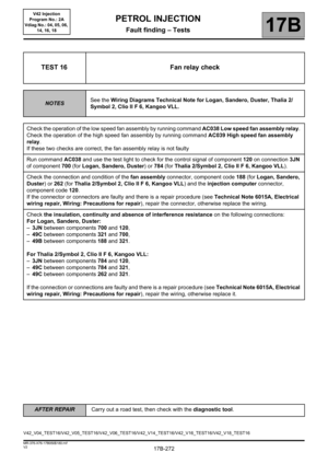
TEST 16 Fan relay check
NOTESSee the Wiring Diagrams Technical Note for Logan, Sandero, Duster, Thalia 2/
Symbol 2, Clio II F 6, Kangoo VLL.
Check the operation of the low speed fan assembly by running command AC038 Low speed fan assembly relay.
Check the operation of the high speed fan assembly by running command AC039 High speed fan assembly
relay.
If these two checks are correct, the fan assembly relay is not faulty
Run command AC038 and use the test light to check for the control signal of component 120 on connection 3JN
of component 700 (for Logan, Sandero, Duster) or 784 (for Thalia 2/Symbol 2, Clio II F 6, Kangoo VLL).
Check the connection and condition of the fan assembly connector, component code 188 (for Logan, Sandero,
Duster) or 262 (for Thalia 2/Symbol 2, Clio II F 6, Kangoo VLL) and the injection computer connector,
component code 120.
If the connector or connectors are faulty and there is a repair procedure (see Technical Note 6015A, Electrical
wiring repair, Wiring: Precautions for repair), repair the connector, otherwise replace the wiring.
Check the insulation, continuity and absence of interference resistance on the following connections:
For Logan, Sandero, Duster:
–3JN between components 700 and 120,
–49C between components 321 and 700,
–49B between components 188 and 321.
For Thalia 2/Symbol 2, Clio II F 6, Kangoo VLL:
–3JN between components 784 and 120,
–49C between components 784 and 321,
–49C between components 262 and 321.
If the connection or connections are faulty and there is a repair procedure (see Technical Note 6015A, Electrical
wiring repair, Wiring: Precautions for repair), repair the wiring, otherwise replace it.
V42_V04_TEST16/V42_V05_TEST16/V42_V06_TEST16/V42_V14_TEST16/V42_V16_TEST16/V42_V18_TEST16