Page 9 of 279

17B-9V2 MR-376-X76-17B050$050.mif
17B
V42 Injection
Program No.: 2A
Vdiag No.: 04, 05, 06,
14, 16, 18
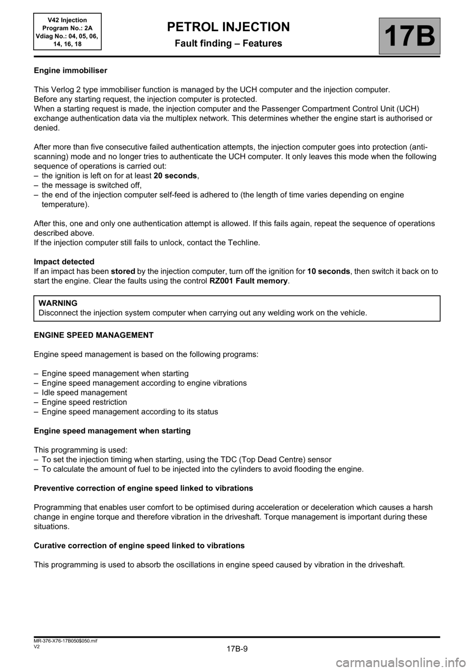
Engine immobiliser
This Verlog 2 type immobiliser function is managed by the UCH computer and the injection computer.
Before any starting request, the injection computer is protected.
When a starting request is made, the injection computer and the Passenger Compartment Control Unit (UCH)
exchange authentication data via the multiplex network. This determines whether the engine start is authorised or
denied.
After more than five consecutive failed authentication attempts, the injection computer goes into protection (anti-
scanning) mode and no longer tries to authenticate the UCH computer. It only leaves this mode when the following
sequence of operations is carried out:
– the ignition is left on for at least 20 seconds,
– the message is switched off,
– the end of the injection computer self-feed is adhered to (the length of time varies depending on engine
temperature).
After this, one and only one authentication attempt is allowed. If this fails again, repeat the sequence of operations
described above.
If the injection computer still fails to unlock, contact the Techline.
Impact detected
If an impact has been stored by the injection computer, turn off the ignition for 10 seconds, then switch it back on to
start the engine. Clear the faults using the control RZ001 Fault memory.
ENGINE SPEED MANAGEMENT
Engine speed management is based on the following programs:
– Engine speed management when starting
– Engine speed management according to engine vibrations
– Idle speed management
– Engine speed restriction
– Engine speed management according to its status
Engine speed management when starting
This programming is used:
– To set the injection timing when starting, using the TDC (Top Dead Centre) sensor
– To calculate the amount of fuel to be injected into the cylinders to avoid flooding the engine.
Preventive correction of engine speed linked to vibrations
Programming that enables user comfort to be optimised during acceleration or deceleration which causes a harsh
change in engine torque and therefore vibration in the driveshaft. Torque management is important during these
situations.
Curative correction of engine speed linked to vibrations
This programming is used to absorb the oscillations in engine speed caused by vibration in the driveshaft.WARNING
Disconnect the injection system computer when carrying out any welding work on the vehicle.
PETROL INJECTION
Fault finding – Features
Page 10 of 279

17B-10V2 MR-376-X76-17B050$050.mif
PETROL INJECTION
Fault finding – Features17B
V42 Injection
Program No.: 2A
Vdiag No.: 04, 05, 06,
14, 16, 18
Idle speed management
This programming is used to calculate the adapted idle speed according to the conditions of use (cold engine, air
conditioning requests, electrical consumer use etc.).
Air supply
This is managed by a motorised throttle valve which is controlled by the injection computer.
The injection computer also performs the following tasks using the motorised throttle:
– management of valve oscillations which can produce undesirable torque,
– management of valve movement subject to mechanical faults when the valve reaches its mechanical boundaries,
– management of acoustic faults by limiting throttle opening at a certain engine speed and when stopping the engine.
Torque management
The torque structure is the system for managing engine torque. It is necessary for some functions such as the
electronic stability program (ESP), automatic transmission (BVA) or sequential gearbox (BVR).
Each computer (ESP, sequential gearbox, automatic transmission) sends a request for torque via the multiplex
network to the injection computer. This arbitrates between the various torque requests and the driver's request
(made via the accelerator pedal or the cruise control/speed limiter).
The result of this arbitration gives the torque setpoint. The computer then calculates the throttle position setpoint, the
ignition advance and the wastegate setpoint (if a turbocharged engine) in order to provide the necessary torque.
Ignition management
Management of ignition advance enables the combustion quality to be managed and therefore engine operation to
be optimised. For a positive advance, the ignition point will be before TDC*, however the advance can have a
negative value.
TDC*: Top Dead Centre.
Fuel supply management
The fuel pump ensures the supply of fuel. It is activated for one second each time the + after ignition feed is switched
on. It ensures the correct level of pressure in the circuit and thereby achieves correct engine starting, particularly if
the vehicle has not been used for a long time. When the engine is running, the pump relay is controlled and
therefore the pump is always active.
The petrol vapour absorber enables petrol vapour to be collected in order to limit its release into the atmosphere.
Richness adjustment
Richness is managed using the upstream and downstream oxygen sensors located on the exhaust. For the sensors
to be operational quickly, they need to be heated by the exhaust gas and by a resistor internal to the sensor. These
sensors reflect the efficiency of combustion and, using information sent to the computer, they enable the quantity of
fuel injected to be managed in order to meet the emission control standards and to ensure optimum engine
operation.
Page 11 of 279
17B-11V2 MR-376-X76-17B050$050.mif
PETROL INJECTION
Fault finding – Features17B
V42 Injection
Program No.: 2A
Vdiag No.: 04, 05, 06,
14, 16, 18
Engine temperature management
The engine is cooled by a 2-speed fan assembly.
To cool the engine, the first speed of the fan assembly is activated if the coolant temperature exceeds 99°C or 94°C
(F4R400/402/403 engines), then the second speed is activated if the temperature exceeds the 102°C or 97°C
(F4R400/402/403 engines). A "very high temperature" warning light illuminates on the instrument panel if the
temperature exceeds 118°C or 113°C (F4R400/402/403 engines).
Page 12 of 279

17B-12V2 MR-376-X76-17B050$060.mif
17B
V42 Injection
Program No.: 2A
Vdiag No.: 04, 05, 06,
14, 16, 18
OPERATIONS FOR REPLACING OR REPROGRAMMING THE COMPUTER
Procedure to be applied before replacement
This procedure must be applied before replacing or reprogramming the injection computer (see MR 388 (Logan and
Sandero), MR 451 (Duster), MR 423 (Thalia 2/Symbol 2), MR 430 (Clio II F 6), or MR 374 (Kangoo VLL),
Mechanical, 17B, Petrol injection, Petrol injection computer: Removal - Refitting).
– Connect the diagnostic tool (mains or cigarette lighter supply).
– Save the data by running command: SC003 Save computer data. In the event of a fault, contact the Techline.
– In the event of a replacement, note the vehicle VIN code using command ID008 VIN code.
– Switch on vehicle + after ignition feed and wait until the coolant temperature is less than 70°C and the air
temperature is less than 50°C. Consult parameter PR064 Coolant temperature and PR059 Air temperature.
– Apply the programming or reprogramming operations described in Technical Note 3585A Computer
(re)programming procedure.
Procedure to be applied after repair:
This procedure must be applied after replacing or reprogramming the computer.
Entering the saved data
– enter the saved data by running command SC001 Write saved data.
Programming the VIN code
– Display the identifier ID008
If the VIN is not entered, enter the VIN. using command VP010 Enter VIN. IMPORTANT:
– The computer permanently stores the immobilisation function code. It is forbidden to perform tests with
computers borrowed from the Parts Department or from another vehicle.
– Connect a battery charger and switch on the vehicle + after ignition feed.
– Switch off all the electrical consumers (lights, interior lighting, air conditioning, radio, etc.).
IMPORTANT:
It is necessary to respect these temperature values in order to carry out the computer programming or
reprogramming operations.
IMPORTANT:
After (re)programming the computer, switch off the + after ignition feed and wait for the loss of communication
message to appear on the diagnostic tool, if the message does not appear, wait for 9 minutes.
Failure to follow this procedure may cause the computer data to be corrupted.
PETROL INJECTION
Fault finding – Replacement of components
Page 13 of 279

17B-13V2 MR-376-X76-17B050$060.mif
PETROL INJECTION
Fault finding – Replacement of components17B
V42 Injection
Program No.: 2A
Vdiag No.: 04, 05, 06,
14, 16, 18
Programming the alcohol level
– Put the vehicle under + after ignition and wait for the value of parameter PR064 Coolant temperature to be greater
than or equal to 80°C.
– There must be no present or stored faults.
– With the ignition on and engine stopped, note the value of PR743 Estimated alcohol level in the tank.
– Carry out resetting using command RZ064 Programming the alcohol level.
– Start the engine and allow the engine to idle for 5 minutes.
– Check the correct programming using parameter PR743; its value must have changed.
– If programming was not performed correctly, repeat the operation from the start.
– If the fault is still present, contact the Techline.
Injection computer initialisation
Start and stop the engine to initialise the computer and wait for the loss of communication message to appear on the
diagnostic tool. If the message does not appear, wait for 9 minutes.
The computer is automatically configured according to the sensors and options present on the vehicle.
If the data were not saved before the operation, carry out the following operations:
– Programming the VIN code
– Enter the V.I.N. using command VP010 Enter VIN.
– Injector programming
Program the injectors by accessing the sub-section entitled Injector replacement operations.
– Programming the TDC sensor
Program the TDC sensor by accessing the sub-section entitled TDC (Top Dead Centre) sensor replacement
operations.
– Programming the motorised throttle
Program the motorised throttle by accessing the sub-section entitled Throttle valve replacement operations.
– Injection computer initialisation
Start and stop the engine to initialise the computer and wait for the loss of communication message to appear on the
diagnostic tool, if the message does not appear, wait for 9 minutes.
The computer is automatically configured according to the sensors and options present on the vehicle.
Page 14 of 279

17B-14V2 MR-376-X76-17B050$060.mif
PETROL INJECTION
Fault finding – Replacement of components17B
V42 Injection
Program No.: 2A
Vdiag No.: 04, 05, 06,
14, 16, 18
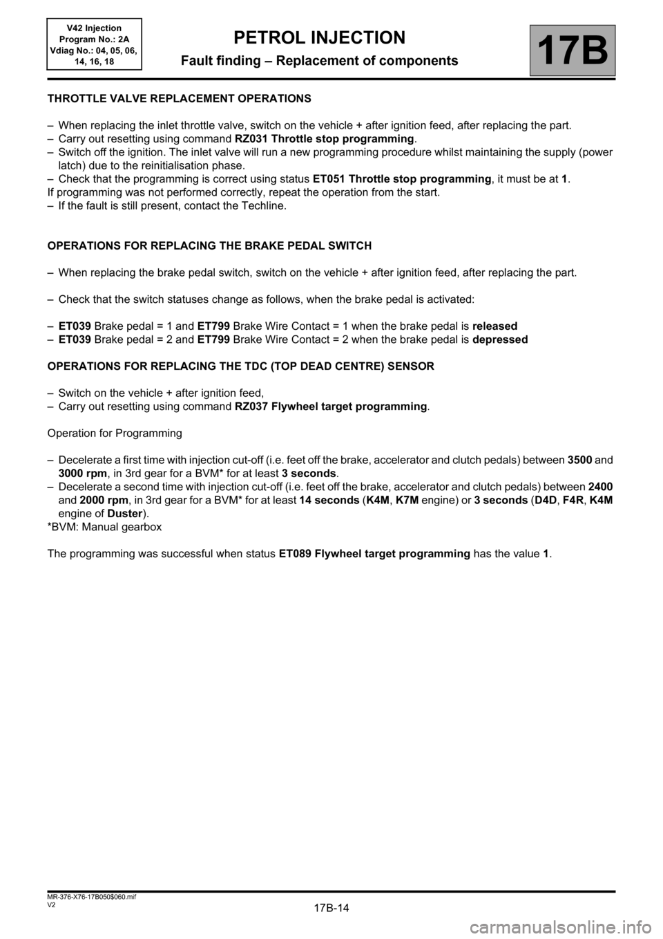
THROTTLE VALVE REPLACEMENT OPERATIONS
– When replacing the inlet throttle valve, switch on the vehicle + after ignition feed, after replacing the part.
– Carry out resetting using command RZ031 Throttle stop programming.
– Switch off the ignition. The inlet valve will run a new programming procedure whilst maintaining the supply (power
latch) due to the reinitialisation phase.
– Check that the programming is correct using status ET051 Throttle stop programming, it must be at 1.
If programming was not performed correctly, repeat the operation from the start.
– If the fault is still present, contact the Techline.
OPERATIONS FOR REPLACING THE BRAKE PEDAL SWITCH
– When replacing the brake pedal switch, switch on the vehicle + after ignition feed, after replacing the part.
– Check that the switch statuses change as follows, when the brake pedal is activated:
–ET039 Brake pedal = 1 and ET799 Brake Wire Contact = 1 when the brake pedal is released
–ET039 Brake pedal = 2 and ET799 Brake Wire Contact = 2 when the brake pedal is depressed
OPERATIONS FOR REPLACING THE TDC (TOP DEAD CENTRE) SENSOR
– Switch on the vehicle + after ignition feed,
– Carry out resetting using command RZ037 Flywheel target programming.
Operation for Programming
– Decelerate a first time with injection cut-off (i.e. feet off the brake, accelerator and clutch pedals) between 3500 and
3000 rpm, in 3rd gear for a BVM* for at least 3 seconds.
– Decelerate a second time with injection cut-off (i.e. feet off the brake, accelerator and clutch pedals) between 2400
and 2000 rpm, in 3rd gear for a BVM* for at least 14 seconds (K4M, K7M engine) or 3 seconds (D4D, F4R, K4M
engine of Duster).
*BVM: Manual gearbox
The programming was successful when status ET089 Flywheel target programming has the value1.
Page 15 of 279

17B-15V2 MR-376-X76-17B050$060.mif
PETROL INJECTION
Fault finding – Replacement of components17B
V42 Injection
Program No.: 2A
Vdiag No.: 04, 05, 06,
14, 16, 18
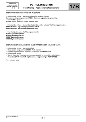
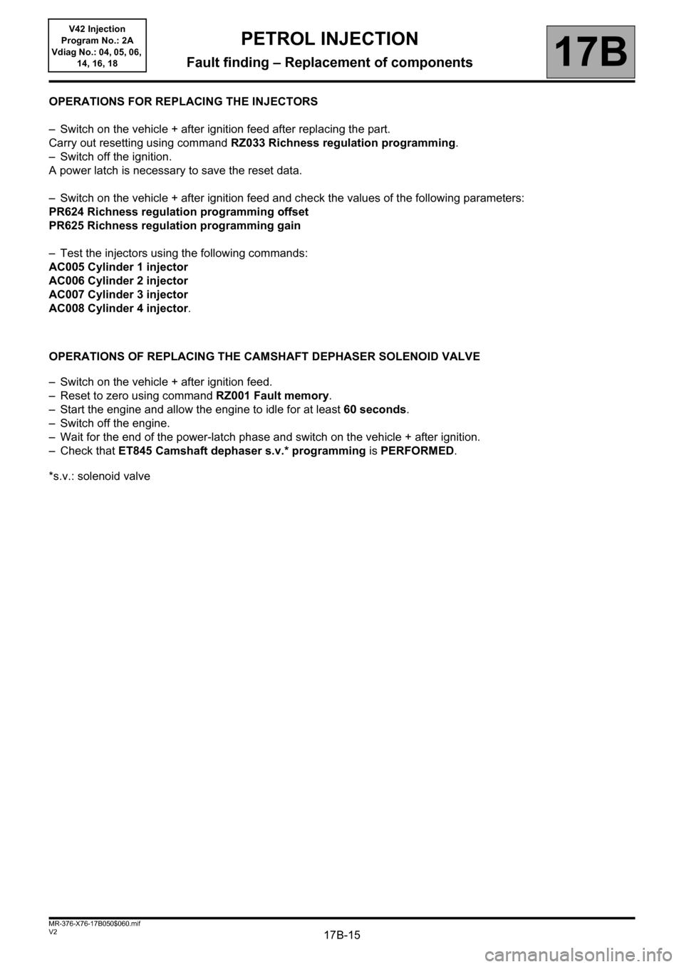
OPERATIONS FOR REPLACING THE INJECTORS
– Switch on the vehicle + after ignition feed after replacing the part.
Carry out resetting using command RZ033 Richness regulation programming.
– Switch off the ignition.
A power latch is necessary to save the reset data.
– Switch on the vehicle + after ignition feed and check the values of the following parameters:
PR624 Richness regulation programming offset
PR625 Richness regulation programming gain
– Test the injectors using the following commands:
AC005 Cylinder 1 injector
AC006 Cylinder 2 injector
AC007 Cylinder 3 injector
AC008 Cylinder 4 injector.
OPERATIONS OF REPLACING THE CAMSHAFT DEPHASER SOLENOID VALVE
– Switch on the vehicle + after ignition feed.
– Reset to zero using command RZ001 Fault memory.
– Start the engine and allow the engine to idle for at least 60 seconds.
– Switch off the engine.
– Wait for the end of the power-latch phase and switch on the vehicle + after ignition.
– Check that ET845 Camshaft dephaser s.v.* programming is PERFORMED.
*s.v.: solenoid valve
Page 16 of 279

17B-16V2 MR-376-X76-17B050$070.mif
17B
V42 Injection
Program No.: 2A
Vdiag No.: 04, 05, 06,
14, 16, 18
Tool fault DTC code Diagnostic tool title
DF0010115 Coolant temperature sensor circuit
DF0020095 Air temperature sensor circuit
DF0110641 Sensor supply voltage no. 1
DF0120651 Sensor supply voltage no. 2
DF0150657 Main relay control circuit
DF0180480 Low-speed fan unit control circuit
DF0260201 Cylinder 1 injector control circuit
DF0270202 Cylinder 2 injector control circuit
DF0280203 Cylinder 3 injector control circuit
DF0290204 Cylinder 4 injector control circuit
DF0380606 Computer
DF0461610 Battery voltage
DF0470560 Computer feed voltage
DF0500571 Brake switch circuit
DF0590301 Misfiring on cylinder 1
DF0600302 Misfiring on cylinder 2
DF0610303 Misfiring on cylinder 3
DF0620304 Misfiring on cylinder 4
DF0650300 Combustion misfire
DF0782100 Motorised throttle control circuit
DF0792119 Motorised throttle valve automatic control
DF0800010 Camshaft dephaser circuit
PETROL INJECTION
Fault finding – Fault summary table