Page 257 of 279
17B-257
AFTER REPAIRCarry out a road test, then check with the diagnostic tool.
V2 MR-376-X76-17B050$180.mif
PETROL INJECTION
Fault finding – Tests17B
V42 Injection
Program No.: 2A
Vdiag No.: 04, 05, 06,
14, 16, 18
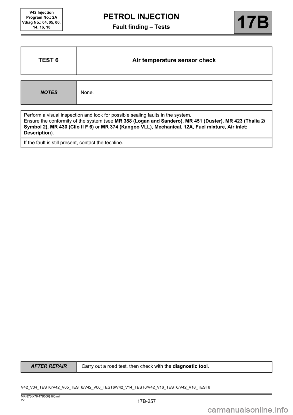
TEST 6 Air temperature sensor check
NOTESNone.
Perform a visual inspection and look for possible sealing faults in the system.
Ensure the conformity of the system (see MR 388 (Logan and Sandero), MR 451 (Duster), MR 423 (Thalia 2/
Symbol 2), MR 430 (Clio II F 6) or MR 374 (Kangoo VLL), Mechanical, 12A, Fuel mixture, Air inlet:
Description).
If the fault is still present, contact the techline.
V42_V04_TEST6/V42_V05_TEST6/V42_V06_TEST6/V42_V14_TEST6/V42_V16_TEST6/V42_V18_TEST6
Page 258 of 279

17B-258
AFTER REPAIRCarry out a road test, then check with the diagnostic tool.
V2 MR-376-X76-17B050$180.mif
PETROL INJECTION
Fault finding – Tests17B
V42 Injection
Program No.: 2A
Vdiag No.: 04, 05, 06,
14, 16, 18
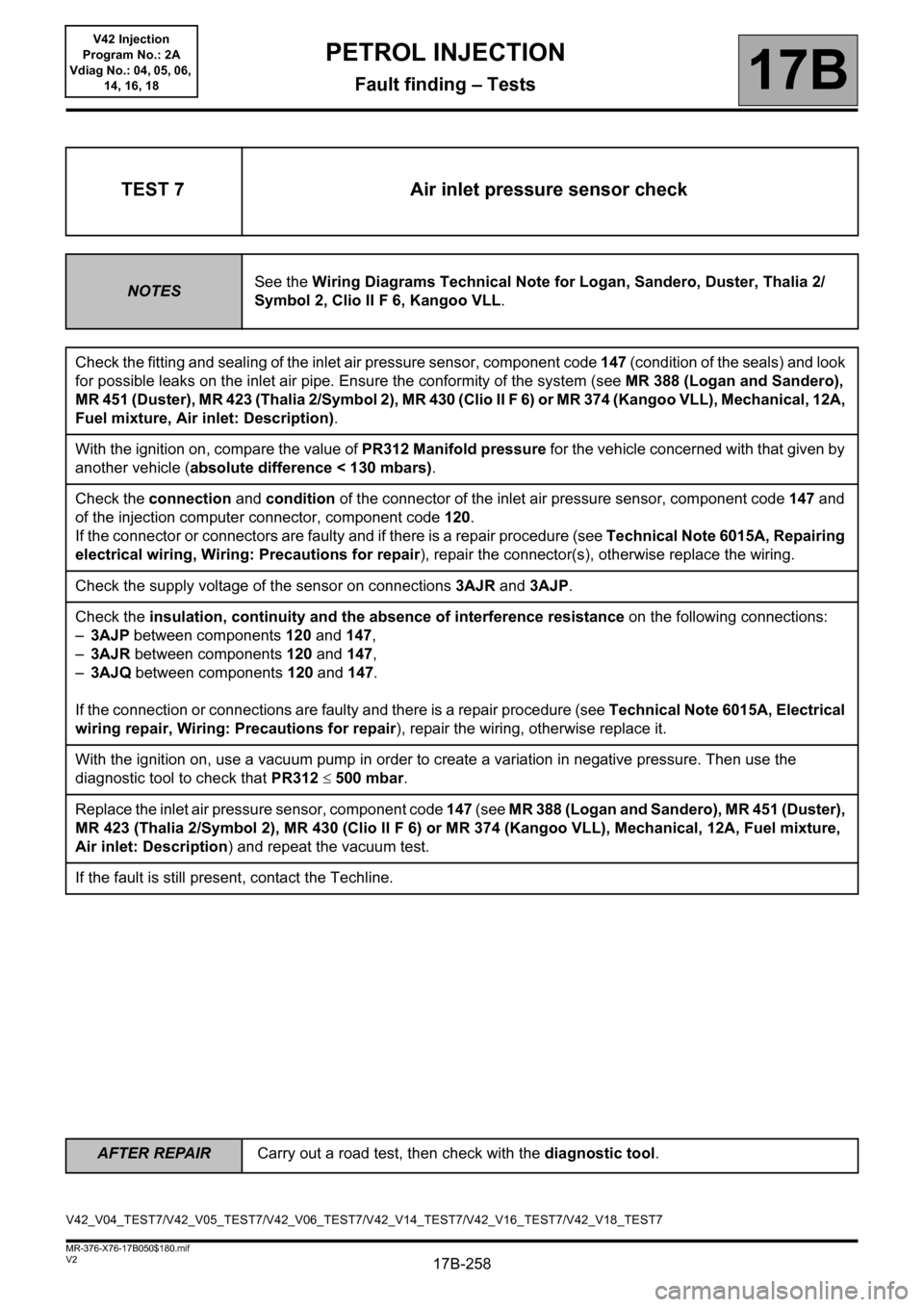
TEST 7 Air inlet pressure sensor check
NOTESSee the Wiring Diagrams Technical Note for Logan, Sandero, Duster, Thalia 2/
Symbol 2, Clio II F 6, Kangoo VLL.
Check the fitting and sealing of the inlet air pressure sensor, component code 147 (condition of the seals) and look
for possible leaks on the inlet air pipe. Ensure the conformity of the system (see MR 388 (Logan and Sandero),
MR 451 (Duster), MR 423 (Thalia 2/Symbol 2), MR 430 (Clio II F 6) or MR 374 (Kangoo VLL), Mechanical, 12A,
Fuel mixture, Air inlet: Description).
With the ignition on, compare the value of PR312 Manifold pressure for the vehicle concerned with that given by
another vehicle (absolute difference < 130 mbars).
Check the connection and condition of the connector of the inlet air pressure sensor, component code 147 and
of the injection computer connector, component code 120.
If the connector or connectors are faulty and if there is a repair procedure (see Technical Note 6015A, Repairing
electrical wiring, Wiring: Precautions for repair), repair the connector(s), otherwise replace the wiring.
Check the supply voltage of the sensor on connections 3AJR and 3AJP.
Check the insulation, continuity and the absence of interference resistance on the following connections:
–3AJP between components 120 and 147,
–3AJR between components 120 and 147,
–3AJQ between components 120 and 147.
If the connection or connections are faulty and there is a repair procedure (see Technical Note 6015A, Electrical
wiring repair, Wiring: Precautions for repair), repair the wiring, otherwise replace it.
With the ignition on, use a vacuum pump in order to create a variation in negative pressure. Then use the
diagnostic tool to check that PR312 500 mbar.
Replace the inlet air pressure sensor, component code 147 (see MR 388 (Logan and Sandero), MR 451 (Duster),
MR 423 (Thalia 2/Symbol 2), MR 430 (Clio II F 6) or MR 374 (Kangoo VLL), Mechanical, 12A, Fuel mixture,
Air inlet: Description) and repeat the vacuum test.
If the fault is still present, contact the Techline.
V42_V04_TEST7/V42_V05_TEST7/V42_V06_TEST7/V42_V14_TEST7/V42_V16_TEST7/V42_V18_TEST7
Page 259 of 279

17B-259
AFTER REPAIRCarry out a road test, then check with the diagnostic tool.
V2 MR-376-X76-17B050$180.mif
PETROL INJECTION
Fault finding – Tests17B
V42 Injection
Program No.: 2A
Vdiag No.: 04, 05, 06,
14, 16, 18
TEST 8 Accelerator pedal potentiometer check
NOTESSee the Wiring Diagrams Technical Note for Logan, Sandero, Duster, Thalia 2/
Symbol 2, Clio II F 6, Kangoo VLL.
Check the variation in PR055 Engine speed when depressing the accelerator pedal (with the engine running).
Stop the engine and switch on the ignition. Without action on the pedal, check that the voltage correction of circuit 1:
–PR147 Pedal potentiometer voltage gang 1 is less than 817 mV and
–PR148 Pedal potentiometer voltage gang 2 is less than 440 mV.
Next, in the "full load" position, check the circuit 1 voltage PR147, which must be greater than 4185 mV, and
PR148, which must be greater than 2013 mV.
Also check the pedal position in the following cases:
– "position zero" (PR030 Accelerator pedal position = 0)
– "Full load" (PR030 = 1).
Stop the engine and then switch on the ignition.
With the vehicle under + after ignition feed, measure the voltage between the following connections:
–3LR and 3LT of component 921,
–3LU and 3LV of component 921.
If the value is not between 4.75 VX5.25 V, check the insulation, the continuity and the absence of
interference resistance of the following connections:
–3LR between components 120 and 921,
–3LT between components 120 and 921,
–3LU between components 120 and 921,
–3LV between components 120 and 921.
If the connection or connections are faulty and there is a repair procedure (see Technical Note 6015A, Electrical
wiring repair, Wiring: Precautions for repair), repair the wiring, otherwise replace it.
Check the insulation, continuity and the absence of interference resistance on the following connections:
–3LS between components 120
and 921,
–3LW between components 120 and 921.
If the connection or connections are faulty and there is a repair procedure (see Technical Note 6015A, Electrical
wiring repair, Wiring: Precautions for repair), repair the wiring, otherwise replace it.
V42_V04_TEST8/V42_V05_TEST8/V42_V06_TEST8/V42_V14_TEST8/V42_V16_TEST8/V42_V18_TEST8
Page 260 of 279

17B-260
AFTER REPAIRCarry out a road test, then check with the diagnostic tool.
V2 MR-376-X76-17B050$180.mif
PETROL INJECTION
Fault finding – Tests17B
V42 Injection
Program No.: 2A
Vdiag No.: 04, 05, 06,
14, 16, 18
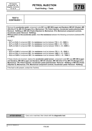
TEST 8
CONTINUED 1
Remove the accelerator pedal, component code 921 (see MR 388 (Logan and Sandero), MR 451 (Duster), MR
430 (Clio II F 6), MR 374 (Kangoo VLL), Mechanical, 17B, Petrol injection, Accelerator pedal potentiometer:
Removal - Refitting or MR 423 (Thalia 2/Symbol 2), Mechanical, 37A, Mechanical component controls,
Accelerator pedal: Removal - Refitting).
Without action on the accelerator pedal, check the resistance between the following connections (between 0°C
and 40ºC):
Gang 1:
–3LT and 3LS of component 921, the resistance must be between 718 X 5263 ,
–3LT and 3LR of component 921, the resistance must be between 838X1742,
–3LR and 3LS of component 921, the resistance must be between 1312X6495.
Gang 2:
–3LV and 3LW of component 921, the resistance must be between 701 X 5242
,
–3LV and 3LU of component 921, the resistance must be between 1495X3105,
–3LU and 3LW of component 921, the resistance must be between 1978X7894.
If these checks are incorrect, replace the accelerator pedal sensor, component code 921 (see MR 388 (Logan
and Sandero), MR 388 (Logan and Sandero), MR 451 (Duster), MR 430 (Clio II F 6), MR 374 (Kangoo VLL),
Mechanical, 17B, Petrol injection, Accelerator pedal potentiometer: Removal - Refitting or MR 423 (Thalia
2/Symbol 2), Mechanical, 37A, Mechanical component controls, Accelerator pedal: Removal - Refitting).
If the fault is still present, contact the Techline.
Page 261 of 279

17B-261
AFTER REPAIRCarry out a road test, then check with the diagnostic tool.
V2 MR-376-X76-17B050$180.mif
PETROL INJECTION
Fault finding – Tests17B
V42 Injection
Program No.: 2A
Vdiag No.: 04, 05, 06,
14, 16, 18
TEST 8
CONTINUED 2
With the accelerator pedal depressed as far as possible, check the resistance between the following
connections (between 0°C and 40ºC):
Gang 1:
–3LT and 3LS of component 921, the resistance must be between 1361 X 6600 ,
–3LT and 3LR of component 921, the resistance must be between 838X1742,
–3LR and 3LS of component 921, the resistance must be between 668 X 5160 .
Gang 2:
–3LV and 3LW of component 921, the resistance must be between 1276 X 6436 ,
–3LV and 3LU of component 921, the resistance must be between 1495X3105,
–3LU and 3LW of component 921, the resistance must be between 1403 X 6700 .
If these checks are incorrect, replace the accelerator pedal sensor, component code 921 (see MR 388 (Logan
and Sandero), MR 388 (Logan and Sandero), MR 451 (Duster), MR 430 (Clio II F 6), MR 374 (Kangoo VLL),
Mechanical, 17B, Petrol injection, Accelerator pedal potentiometer: Removal - Refitting or MR 423 (Thalia
2/Symbol 2), Mechanical, 37A, Mechanical component controls, Accelerator pedal: Removal - Refitting).
If the fault is still present, contact the Techline.
Page 262 of 279

17B-262
AFTER REPAIRCarry out a road test, then check with the diagnostic tool.
V2 MR-376-X76-17B050$180.mif
PETROL INJECTION
Fault finding – Tests17B
V42 Injection
Program No.: 2A
Vdiag No.: 04, 05, 06,
14, 16, 18
TEST 9 Brake pedal switch check
NOTESSee the Wiring Diagrams Technical Note for Logan, Sandero, Duster, Thalia 2/
Symbol 2, Clio II F 6, Kangoo VLL.
With the brake pedal released, check ET039 Brake pedal and ET799 Brake wire contact.
ET039 must be 01 and ET799 must be 01.
While depressing the brake pedal, check ET039 and ET799.
ET039 must be 02 and ET799 must be 02.
If these two checks are correct, the switch is not faulty.
Check the fitting and mechanical operation of the brake pedal (the pedal returns properly).
If the check is incorrect, check the braking system.
With the brake pedal depressed, measure the resistance of the brake pedal switch, component code 160
between connections AP1 (for Logan, Sandero, Duster) or AP10 (for Thalia 2/Symbol 2, Clio II F 6, Kangoo
VLL) and 65A. The value must be X > 10 M (between 0°C and 40°C).
If the resistance is not correct, replace the brake pedal switch, component code 160 (see MR 388 (Logan and
Sandero), MR 451 (Duster), MR 423 (Thalia 2/Symbol 2), MR 430 (Clio II F 6) or MR 374 (Kangoo VLL),
Mechanical, 37A, Mechanical component controls, Brake pedal switch: Removal - Refitting).
With the brake pedal released, measure the resistance of the brake pedal switch, component code 160 between
connections AP1 (for Logan, Sandero, Duster) or AP10 (for Thalia 2/Symbol 2, Clio II F 6, Kangoo VLL) and
5A. The value must be between 0 < X < 1 (between
0°C and 40°C).
If the resistance is not correct, replace the brake pedal switch, component code 160 (see MR 388 (Logan and
Sandero), MR 451 (Duster), MR 423 (Thalia 2/Symbol 2), MR 430 (Clio II F 6) or MR 374 (Kangoo VLL),
Mechanical, 37A, Mechanical component controls, Brake pedal switch: Removal - Refitting) and move on
to the Section: Checking the brake pedal switch.
Check the condition of the brake pedal switch connector, component code 160 (see MR 388 (Logan and
Sandero), MR 451 (Duster), MR 423 (Thalia 2/Symbol 2), MR 430 (Clio II F 6) or MR 374 (Kangoo VLL),
Mechanical, 37A, Mechanical component controls, Brake pedal switch: Removal - Refitting).
If the connector is faulty and there is a repair method (see Technical Note 6015A, Repairing electrical wiring,
Wiring: Precautions for repair), repair the connector, otherwise replace the wiring.
V42_V04_TEST9/V42_V05_TEST9/V42_V06_TEST9/V42_V14_TEST9/V42_V16_TEST9/V42_V18_TEST9
Page 263 of 279

17B-263
AFTER REPAIRCarry out a road test, then check with the diagnostic tool.
V2 MR-376-X76-17B050$180.mif
PETROL INJECTION
Fault finding – Tests17B
V42 Injection
Program No.: 2A
Vdiag No.: 04, 05, 06,
14, 16, 18
TEST 9
CONTINUED
Check the presence and condition of brake pedal fuse F03 (for Logan, Sandero, Duster), F4 (for Thalia 2/Symbol
2, Clio II F 6) or F16 (for Kangoo VLL).
Check the insulation, continuity and the absence of interference resistance on the following connections:
–AP1 between components 160 and 1016 (for Logan, Sandero, Duster),
–AP10 between components 160 and 1016 (for Thalia 2/Symbol 2, Clio II F 6)
–AP10 between components 160 and 260 (for Kangoo VLL),
–5A between components 160 and 120,
–65A between components 160 and120,
If the connection or connections are faulty and there is a repair procedure (see Technical Note 6015A, Electrical
wiring repair, Wiring: Precautions for repair), repair the wiring, otherwise replace it.
If the fault is still present, contact the Techline.
Page 264 of 279

17B-264
AFTER REPAIRCarry out a road test, then check with the diagnostic tool.
V2 MR-376-X76-17B050$180.mif
PETROL INJECTION
Fault finding – Tests17B
V42 Injection
Program No.: 2A
Vdiag No.: 04, 05, 06,
14, 16, 18
TEST 10 TDC sensor check
NOTESSee the Wiring Diagrams Technical Note for Logan, Sandero, Duster, Thalia 2/
Symbol 2, Clio II F 6, Kangoo VLL.
Check the sensor fitting (connectors, mountings, etc.) (see MR 388 (Logan and Sandero), MR 451 (Duster), MR
423 (Thalia 2/Symbol 2), MR 430 (Clio II F 6) or MR 374 (Kangoo VLL), Mechanical, 17B, Petrol Injection,
Crankshaft position sensor: Removal - Refitting).
Switch on the ignition, check the change of the engine rotation speed using parameter PR055 Engine speed. The
value must be between 0 rpm and more than 120 rpm when the starter is operating.
With the engine running, accelerate to obtain different engine rotation speeds and check that the engine speed
correctly changes in relation to the accelerations.
If PR055 varies, the sensor is sound.
Check the cleanliness and condition of the TDC sensor, component code 149 and of the injection computer
connector, component code 120.
If the connector or connectors are faulty and if there is a repair procedure (see Technical Note 6015A, Repairing
electrical wiring, Wiring: Precautions for repair), repair the connector(s), otherwise replace the wiring.
V42_V04_TEST10/V42_V05_TEST10/V42_V06_TEST10/V42_V14_TEST10/V42_V16_TEST10/V42_V18_TEST10