Page 17 of 279

17B-17V2 MR-376-X76-17B050$070.mif
PETROL INJECTION
Fault finding – Fault summary table17B
V42 Injection
Program No.: 2A
Vdiag No.: 04, 05, 06,
14, 16, 18
*Info: InformationTool fault DTC code Diagnostic tool title
DF0810443 Canister bleed solenoid valve circuit
DF0820135 Upstream oxygen sensor heating circuit
DF0830141 Downstream oxygen sensor heating circuit
DF0850627 Fuel pump relay control circuit
DF0880325 Pinking sensor circuit
DF0910500 Vehicle speed signal
DF0920130 Upstream oxygen sensor circuit
DF0930136 Downstream oxygen sensor circuit
DF0950120 Throttle potentiometer circuit gang1
DF0960220 Throttle potentiometer circuit gang 2
DF101C121 ESP multiplex connection
DF1022503 Available alternator power sig.*
DF108C108 LPG/CNG computer multiplex connection
DF1090313 Low fuel level misfire
DF1200335 Engine speed sensor signal
DF1950016 Camshaft sensor / engine speed consistency
DF3190340 Camshaft sensor circuit
DF3420650 Malfunction indicator light circuit
DF3581608 Injector control computer
DF3611351 Ignition coil circuit 1-4
DF3621352 Ignition coil 2-3 circuit
DF3630011 Camshaft dephaser
DF37910A4 Cylinder injector 1 control
Page 18 of 279
17B-18V2 MR-376-X76-17B050$070.mif
PETROL INJECTION
Fault finding – Fault summary table17B
V42 Injection
Program No.: 2A
Vdiag No.: 04, 05, 06,
14, 16, 18
Tool fault DTC code Diagnostic tool title
DF38010A5 Cylinder 2 injector control
DF38110A6 Cylinder 3 injector control
DF38210A7 Cylinder injector 4 command
DF3940420 Catalytic converter operating fault
DF3980170 Fuel circuit operating fault
DF4090461 Fuel level sensor circuit
DF4361314 Detection of engine misfiring
DF4570315 Flywheel target
DF504C101 Automatic transmission
DF5310618 LPG system
DF5322502 Alternator charge signal
DF5562135 Pedal/throttle position consistency
DF6310703 Brake light switch signal
DF6331170 LPG fuel circuit operating fault
DF6351301 LPG cylinder 1 misfire
DF6361302 LPG cylinder 2 misfire
DF6371303 LPG cylinder 3 misfire
DF6381304 LPG cylinder 4 misfire
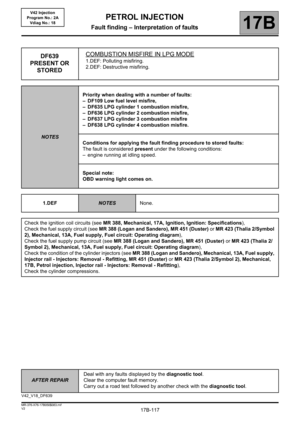
DF6391300 Combustion misfire in LPG mode
DF648060A Computer
DF7210217 Engine overheating
DF7732294 Pressure regulator circuit
Page 19 of 279
17B-19V2 MR-376-X76-17B050$070.mif
PETROL INJECTION
Fault finding – Fault summary table17B
V42 Injection
Program No.: 2A
Vdiag No.: 04, 05, 06,
14, 16, 18
*Refriger: RefrigerantTool fault DTC code Diagnostic tool title
DF8842632 Additional fuel circuit pump relay
DF8870226 Brake - accelerator pedal position
DF8941633 Additional fuel circuit solenoid valve
DF9740225 Pedal potentiometer circuit gang 1
DF9752120 Pedal potentiometer circuit gang 2
DF9921644 Additional heater 1 relay circuit
DF9931645 Additional heater 2 relay circuit
DF9941646 Additional heater 3 relay circuit
DF10150504 Brake switch signal consistency
DF10160833 Clutch switch signal consistency
DF1017061A Computer
DF10340314 Combustion misfire
DF10580106 Inlet pressure consistency
DF1063C415 ESP multiplex connection
DF10680530 Refriger* pressure sensor voltage
DF10720645 Air conditioning compressor relay control
DF10740638 Motorised throttle position inconsistent
Page 20 of 279
17B-20V2 MR-376-X76-17B050$070.mif
PETROL INJECTION
Fault finding – Fault summary table17B
V42 Injection
Program No.: 2A
Vdiag No.: 04, 05, 06,
14, 16, 18
*Refriger: RefrigerantTool fault DTC code Diagnostic tool title
DF1235C402 Automatic transmission
DF1265018A LPG pressure sensor circuit
DF12670184 LPG temperature sensor circuit
DF13011570 Status of LPG switch
DF13551656 Multiplexed torque regulator connection
DF13610185 LPG temperature sensor circuit
DF13622666 Tank solenoid valve circuit
DF13632293 LPG pressure
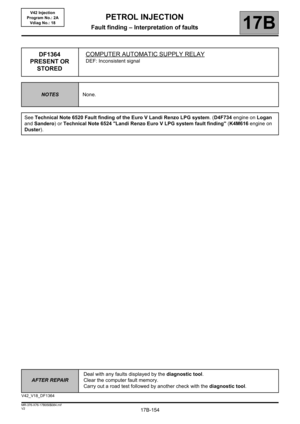
DF1364109A Computer automatic supply relay
DF13652265 LPG tank sender signal voltage
DF136610A0 Cylinder 1 LPG injector circuit
DF136710A1 Cylinder 2 LPG injector circuit
DF136810A2 Cylinder 3 LPG injector circuit
DF136910A3 Cylinder 4 LPG injector circuit
Page 21 of 279

17B-21
AFTER REPAIRDeal with any faults displayed by the diagnostic tool.
Clear the computer fault memory.
Carry out a road test followed by another check with the diagnostic tool.
V2 MR-376-X76-17B050$081.mif
17B
V42 Injection
Program No.: 2A
Vdiag No.: 04, 05, 06,
14, 16, 18
DF001
PRESENT OR
STOREDCOOLANT TEMPERATURE SENSOR CIRCUIT4.DEF: Voltage too low
5.DEF: Voltage too high
6.DEF: Micro-cut
NOTESSpecial notes:
– The OBD and Level 1 warning lights illuminate.
See the Wiring Diagrams Technical Note for Logan, Sandero, Duster, Thalia 2/
Symbol 2, Clio II F 6, Kangoo VLL.
Check the connection and condition of the connector of the coolant temperature sensor, component code 244
and of the connections of the injection computer, component code 120.
If the connector(s) are faulty and if there is a repair procedure (see Technical Note 6015A, Repairing electrical
wiring, Wiring: Precautions for repair), repair the connector, otherwise replace the wiring.
Disconnect the connector of the injection computer, component code 120 (see MR 388 (Logan and Sandero), MR
451 (Duster), MR 423 (Thalia 2/Symbol 2), MR 430 (Clio II F 6) or MR 374 (Kangoo VLL), Mechanical, 17B,
Petrol injection, Petrol injection computer: Removal - Refitting).
Measure the resistance of component 244 by connections 3JK and 3C of the injection computer connector,
component code 120.
If the resistance of the coolant temperature sensor, component code 244 is not between 100 X 10 k (K7M,
K4M, D4D engines), 85 X 82 k (Duster F4R and K4M engine) at ambient temperature: replace the coolant
temperature sensor, component code 244 (see MR 388 (Logan and Sandero), MR 451 (Duster), MR 423 (Thalia
2/Symbol 2), MR 430 (Clio II F 6) or MR 374 (Kangoo VLL), Mechanical, 19A, Cooling, Coolant temperature
sensor: Removal - Refitting).
Check the insulation, continuity and absence of interference resistance on the following connections:
–3JK between components 120 and 244.
–3C between components 120 and 244.
If the connection or connections are faulty and if there is a repair method (see Technical Note 6015A, Electrical
wiring repair, Wiring: Precautions for repair), repair the wiring, otherwise replace the wiring.
If the fault is still present, contact the Techline.
V42_V04_DF001/ V42_V05_DF001/V42_V06_DF001/V42_V14_DF001/V42_V16_DF001/V42_V18_DF001
PETROL INJECTION
Fault finding – Interpretation of faults
Page 22 of 279

17B-22
AFTER REPAIRDeal with any faults displayed by the diagnostic tool.
Clear the computer fault memory.
Carry out a road test followed by another check with the diagnostic tool.
V2 MR-376-X76-17B050$081.mif
PETROL INJECTION
Fault finding – Interpretation of faults17B
V42 Injection
Program No.: 2A
Vdiag No.: 04, 05, 06,
14, 16, 18
DF002
PRESENT OR
STOREDAIR TEMPERATURE SENSOR CIRCUIT2.DEF: Signal outside lower limit.
3.DEF: Signal outside upper limit.
NOTESSpecial notes:
– The OBD and Level 1 warning lights illuminate.
See the Wiring Diagrams Technical Note for Logan, Sandero, Duster, Thalia 2/
Symbol 2, Clio II F 6, Kangoo VLL.
Check the connection and condition of the connector of the air temperature sensor, component code 272 and of
the connections of the injection computer, component code 120.
If the connector or connectors are faulty and there is a repair procedure (see Technical Note 6015A, Electrical
wiring repair, Wiring: Precautions for repair), repair the connector, otherwise replace the wiring.
Measure the resistance of the air temperature sensor, component code 272 between connections 3B and 3JQ.
If the resistance measured is not between 300 X 6 k or 100 X 50 k (Duster F4R engine) or 50
X 50 k (Duster K4M engine) at ambient temperature: replace the air temperature sensor, component code
272.
Check the insulation, continuity and absence of interference resistance on the following connections:
–3B between components 272 and 120.
–3JQ between components 272 and 120.
If the connection or connections are faulty and if there is a repair method (see Technical Note 6015A, Electrical
wiring repair, Wiring: Precautions for repair
), repair the wiring, otherwise replace the wiring.
If the fault is still present, contact the Techline.
V42_V04_DF002/ V42_V05_DF002/V42_V06_DF002/V42_V14_DF002/V42_V16_DF002/V42_V18_DF002
Page 23 of 279

17B-23
AFTER REPAIRDeal with any faults displayed by the diagnostic tool.
Clear the computer fault memory.
Carry out a road test followed by another check with the diagnostic tool.
V2 MR-376-X76-17B050$081.mif
PETROL INJECTION
Fault finding – Interpretation of faults17B
V42 Injection
Program No.: 2A
Vdiag No.: 04, 05, 06,
14, 16, 18
DF011
PRESENT OR
STOREDSENSOR FEED VOLTAGE NO. 11.DEF: Above maximum threshold.
2.DEF: Below minimum threshold.
NOTESSpecial notes:
– The OBD and Level 2 warning lights illuminate.
See the Wiring Diagrams Technical Note for Logan, Sandero, Duster, Thalia 2/
Symbol 2, Clio II F 6, Kangoo VLL.
Disconnect the accelerator pedal sensor gang 1, component code 921 then switch on the ignition. Wait several
seconds so that the computer can update the fault status.
If the fault changes from present to stored: Replace the accelerator pedal sensor gang 1, component code 921
(see MR 388 (Logan and Sandero), MR 451 (Duster) MR 423 (Thalia 2/Symbol 2), MR 430 (Clio II F 6) or MR
374 (Kangoo VLL), Mechanical, 37A, Mechanical component controls, Accelerator pedal: Removal -
Refitting).
Disconnect the motorised throttle valve, component code 1076 then switch on the ignition (see MR 388 (Logan
and Sandero), MR 451 (Duster), MR 423 (Thalia 2/Symbol 2), MR 430 (Clio II F 6) or MR 374 (Kangoo VLL),
Mechanical, 12A, Fuel mixture, Throttle valve: Removal - Refitting).
Wait several seconds so that the computer can update the fault status.
If the fault changes from present to stored: Replace the damper valve position sensor, component code 1076, (see
MR 388 (Logan and Sandero), MR 451 (Duster) or MR 423 (Thalia 2/Symbol 2), MR 430 (Clio II F 6) or MR
374 (Kangoo VLL), Mechanical, 12A, Fuel mixture, Throttle valve: Removal - Refitting) referring to the
Replacement of components section.
Check the insulation, continuity and the absence of interference resistance on the following connections:
–3LR between components 921 and 120,
–3LT between components 921 and 120,
–3MN between components 1076 and 120,
–3MO between components 1076 and 120.
If the connection or connections are faulty and there is a repair procedure (see Technical Note 6015A, Electrical
wiring repair, Wiring: Precautions for repair), repair the wiring, otherwise replace it.
If the fault is still present, contact the Techline.
V42_V04_DF011/ V42_V05_DF011/V42_V06_DF011/V42_V14_DF011/V42_V16_DF011/V42_V18_DF011
Page 24 of 279

17B-24
AFTER REPAIRDeal with any faults displayed by the diagnostic tool.
Clear the computer fault memory.
Carry out a road test followed by another check with the diagnostic tool.
V2 MR-376-X76-17B050$081.mif
PETROL INJECTION
Fault finding – Interpretation of faults17B
V42 Injection
Program No.: 2A
Vdiag No.: 04, 05, 06,
14, 16, 18
DF012
PRESENT OR
STOREDSENSOR SUPPLY VOLTAGE NO. 21.DEF: Above maximum threshold.
2.DEF: Below minimum threshold.
NOTESSpecial notes:
– The OBD and Level 2 warning lights illuminate.
See the Wiring Diagrams Technical Note for Logan, Sandero, Duster, Thalia 2/
Symbol 2, Clio II F 6, Kangoo VLL.
Disconnect the accelerator pedal sensor gang 2, component code 921 then switch on the ignition (see MR 388
(Logan and Sandero), MR 451 (Duster), MR 423 (Thalia 2/Symbol 2), MR 430 (Clio II F 6) or MR 374 (Kangoo
VLL), Mechanical, 37A, Mechanical component controls, Accelerator pedal: Removal - Refitting).
Wait several seconds so that the computer can update the fault status.
If the fault changes from present to stored: Replace the accelerator pedal sensor gang 2, component code 921
(see MR 388 (Logan and Sandero), MR 451 (Duster) or MR 423 (Thalia 2/Symbol 2), Mechanical, 37A,
Mechanical component controls, Accelerator pedal: Removal - Refitting).
Disconnect the manifold pressure sensor, component code 147, then switch on the ignition.
Wait several seconds so that the computer can update the fault status.
If the fault changes from present to stored: Replace the inlet pressure sensor, component code 147.
Disconnect the Freon pressure sensor, component code 1202, then switch on the ignition (see MR 388 (Logan
and Sandero), MR 451 (Duster), MR 423 (Thalia 2/Symbol 2), MR 430 (Clio II F 6) or MR 374 (Kangoo VLL),
Mechanical, 62A, Air conditioning, Pressure sensor: Removal - Refitting).
Wait several seconds so that the computer can update the fault status.
If the fault changes from present to stored: Replace the Freon pressure sensor, component code 1202 (see MR
388 (Logan and Sandero), MR 451 (Duster), MR 423 (Thalia 2/Symbol 2), MR 430 (Clio II F 6) or MR 374
(Kangoo VLL), Mechanical, 62A, Air conditioning, Pressure sensor: Removal - Refitting).
Check the insulation, continuity and the absence of interference resistance on the following connections:
–3LU between components 921 and 120,
–3LV between components 921 and 120,
–3AJP between components 147 and 120,
–3AJR between components 147 and 120,
–38Y between components 1202 and 120,
–38U between components 1202 and 120.
If the connection or connections are faulty and there is a repair procedure (see Technical Note 6015A, Electrical
wiring repair, Wiring: Precautions for repair), repair the wiring, otherwise replace it.
If the fault is still present, contact the Techline.
V42_V04_DF012/ V42_V05_DF012/V42_V06_DF012/V42_V14_DF012/V42_V16_DF012/V42_V18_DF012